Abstract
Because of the self-locking part inertia, deformation factors, and interspace between the driving and driven sides of the overrunning clutch, the existing dynamic models, which consider the rotational speed discrepancy or angle discrepancy as the only determinant to recognize the engaging state, have some difficulty in accurately describing and studying the dynamic characteristics of the overrunning clutch and its transmission system. In order to solve these problems, this paper proposed a modified method considering the influence of the dynamic characteristics of self-locking components through angle compensation. Four models were established on a MATLAB/Simulink platform, and an experiment was carried out on a transmission experimental platform under a stable driving torque and varying driving torque. Then, the comparison of the dynamic characteristic between the simulation and the experiment showed that under non-stationary excitation, taking the influence of the dynamic characteristic of the self-locking components into account through angle compensation can help to more accurately describe the dynamic characteristics of a transmission system with an overrunning clutch.
1. Introduction
Overrunning clutch is a kind of basic mechanical component that transmits power in one way. The clutch is currently applied in many kinds of mechanical systems because it can switch its state by itself with a change in the rotational speed and direction between the driving and driven components. For example, it can be used on vehicles to realize the separate functions of the engine and starter [1], torque converters to restrict the one-way guide rotation [2] and driving systems for front-end accessories of the engine to realize a shock-absorbing function [3, 4]. Research on overrunning clutches has mainly concentrated on the mechanism design and reliability analysis corresponding to the application environment [5-7], analysis of contact stress, fatigue life and overload capacity [8-10], and dynamic characteristic of the overrunning clutch [11-14] and its transmission system.
Depending on the modeling method, the dynamic models of the overrunning clutch are divided into physical models and mathematical models based on the finite element software or multi-body dynamics software. The physical models are used to research the self-characteristics of the overrunning clutch, and the mathematical models are used to study the dynamic characteristics of the transmission system [15]. Most of the existing mathematical models are spring damping models without rotational inertia, which regard the rotational speed difference [16] and the angle difference [12, 13] as the determination to recognize the state of the clutch. The engagement of the overrunning clutch is the combined action of the driving side and self-locking components, the driven side and self-components. Because of the inertia of the self-locking part, deformation factors, and interspace between the driving and driven sides, an idle angle appears during engagement [17]. The synchronization performance of the clutch can meet the needs in the case where the idle angle is not strictly restricted. But the idle angle may affect the dynamic characteristics when the frequent switching between overrunning and engaging occurs under the non-stationary excitation.
With the development of the multi-model and controllability technology, related studies on the application of the overrunning clutch on automatic transmissions have been conducted [18-20]. Describing the dynamic characteristics more correctly and increasing the precision of the mathematical models can better support the research on the dynamic characteristics of the overrunning clutch and its transmission chain. On the basis of the traditional dynamic mathematical model, this paper proposes a modified method considering the influence of the dynamic characteristics of the self-locking part through angle compensation. From the four types of overrunning clutch models, the dynamic model of the overrunning clutch-single gear pair system was established on a MATLAB/Simulink platform under both stable and varying driving torques. Compared with the experiment, the accuracy of the four models was analyzed.
2. Dynamic model
2.1. Overrunning clutch model
The study of the dynamic characteristics of the transmission system is based on the mathematical models of each component. Controllable overrunning clutch applied in automotive transmission systems is always installed in the middle of the shafts and gears to control the power transmission. All the components in the traditional overrunning clutch model have always been simplified as inertial components without elastic damping elements and elastic damping components without inertial elements. When the overrunning clutch is in engagement, it is considered as an elastic damping component without an inertial element, because the driving gears and the driven sides are rigidly connected with the shafts and gears, and their inertia is also contained in the inertia of the shafts and gears. This is considered in mathematical models of the overrunning clutch to judge the state of the clutch. At present, the rotational speed difference and the angle difference between the driving gears and driven gears are generally used as the basis for judging the connection state. The models based on these determinants are called as the “rotational speed discrepancy model” and the “rotational angle discrepancy model.” The torques transmitted by the overrunning clutch in these models are expressed as Eqs. (1) and (2). θm(t), θs(t) are the rotational angles of the driving side and the driven side of the overrunning clutch, respectively, in rad. Kc is the torsional rigidity of the clutch, in N·m/rad. Cc is the damping coefficient. Mc(t) is the torque transmitted by the clutch, in N·m:
The engagement of the overrunning clutch consists in the combined action of the driving side and the self-locking components, driven side, and self-components. Because of the inertia of the self-locking part, deformation factors, and interspace between the driving and driven sides, an idle angle appears during engagement. This means that the driving components or the driven components still need to turn a relative angle to enter the engaging state substantially, which means the torque can be transmitted after the driving components and the driven components to satisfy the engaging state. Thus, Eqs. (1) and (2) do not account for the influence of the dynamic characteristics of the self-locking components.
The transmission system always works under non-stationary excitation from the power source and the load, such as cyclic excitation from the automotive engine and vibrational excitation from the pavement. When the overrunning clutch is installed in the main transmission chain, its working state frequently switches from engaging to overrunning and to engaging under non-stationary excitation. The idle angle also accumulates with increased switching times of the clutch in the transmission process. Obviously, the accumulation of idle angle will lead to large errors in the elastic force calculated by Eqs. (1) and (2).
By accounting for the impact of the dynamic characteristics of self-locking components, an assumption can be made to eliminate errors caused by the accumulation of idle angle through angle compensation, as shown in Eq. (3). Δθαv(t) is the angle compensation in the rotational speed discrepancy model, and the rotational speed discrepancy model with an angle compensation is expressed as Eq. (4). Δθɑ(t) is the angle compensation in the rotational angle discrepancy model, and the rotational angle discrepancy model with angle compensation is expressed as Eq. (6):
2.2. Dynamic model of overrunning clutch-single gear pair system
The dynamic model of the overrunning clutch-single gear pair system is established as shown in Fig. 1. The system consists of the inertia of the input end, overrunning clutch, input gears, output gears, and the inertia of the output end. The output gears connect rigidly with the output end, and its inertia is also contained in the inertia of the output end. To explain it, this combination is called as the “output combination”.
Fig. 1Dynamic model of overrunning clutch-single gear pair system
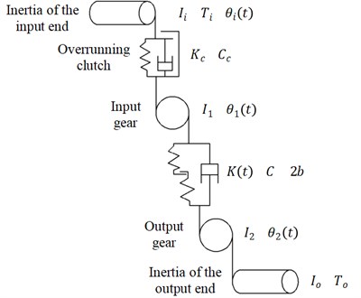
As shown in Fig. 1, Ii, I1, I2, and Io are the rotary inertia of the input end, input gear, output gear, and output end, respectively, in kg·m2. Thus, the rotary inertia of the output combination is equal to I2 plus Io. θi(t), θ1(t), and θ2(t) are the rotated angles of the input end, input gear, and output combination, respectively, in rad. r1 and r2 are the basic circle radiuses of the input gear and the output gear, respectively, in m. Ti is the driving torque acting on the input end, in N·m. To is the load torque acting on the output combination, in N·m. C is the damping coefficient in the meshing process of gear pair. Cc is the damping coefficient of the overrunning clutch. K(t) is the time-varying mesh stiffness of the gear pairs, in N/m. Kc is the torsional stiffness of the overrunning clutch, in N·m/rad.
By simplifying the input end, including the driving side of the overrunning clutch; the input gear, including the driven side of the clutch; and the output combination to the inertial components, and simplifying the engagement of the clutch and gears to the elastic damping elements without inertia, the motion differential equation is derived as Eq. (7). β(t) is the nonlinear function of the gear side clearance while engaging. K(t) is the time-varying meshing stiffness based on the multilevel fitting stiffness model proposed in the literature [7]. The definitions of the damping coefficient and the non-linear function of the gear side clearance are also described in the literature [7]:
3. Comparison and simulation analysis
3.1. Simulation model establishment
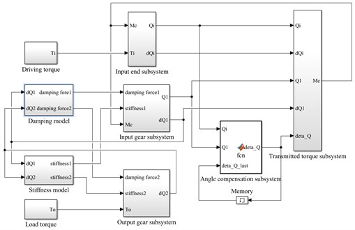
From the four overrunning clutch models shown in Eqs. (1), (2), (4) and (6), and the dynamic model of the overrunning clutch-single gear pair system shown in (7). The simulation models of rotational speed discrepancy model with angle compensation and rotational angle discrepancy model with angle compensation were established in Simulink as shown in Fig. 2 and Fig. 3. The main parameters of the models are shown in Table 1.
In Fig. 2 and Fig. 3, the differential equations shown in Eq. (7) are implemented by input end subsystem, input gear subsystem and output gear subsystem. The calculation of damping force and stiffness in the meshing process in Eq. (7) are transferred to the damping models and stiffness models. In addition, Eqs. (3) and (4) are implemented by angle compensation subsystem and transmitted torque subsystem of rotational speed discrepancy model with angle compensation in Fig. 2, while Eqs. (5) and (6) are implemented by the same subsystems in rotational angle discrepancy model with angle compensation in Fig. 3. In these subsystems, Mc, To and Ti represent the transmitted torque, load torque and driving torque. Qi, Q1 and Q2 represent the rotational angles of input end, input gear and output gear, while dQi, dQ1 and dQ2 represent the corresponding rotational speeds.
Table 1Simulation parameters of overrunning clutch-single gear pair system
Item | Value |
Inertia of input end (Ii) | 5×10⁻³ kg·m2 |
Torsional stiffness of overrunning clutch (Kc) | 2000 N·m/rad |
Damping coefficient of overrunning clutch (Cc) | 0.063 N·m·s/rad |
Number of teeth on input gears | 15 |
Number of teeth on output gears | 17 |
Basic circle radius of input gear (r1) | 67.5×10⁻³ m |
Basic circle radius of input gear (r2) | 76.5×10⁻³ m |
Rotary inertia of input gear (I1) | 3.8×10⁻⁴ kg·m2 |
Rotary inertia of output gear (I2) | 4×10⁻⁴ kg·m2 |
Rotary inertia of output end (Io) | 0.15 kg·m2 |
Mean meshing stiffness of gear (K) | 1×10⁸ N/m |
Meshing damping coefficient of gear (C) | 403.66 N·s/m |
Fig. 2Simulation model based on Simulink for rotational speed discrepancy model with angle compensation
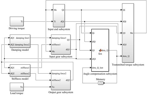
Fig. 3Simulation model based on Simulink for rotational angle discrepancy model with angle compensation
To perform a full analysis and comparison of the four models, the simulation was conducted under two typical conditions of stable and varying driving torques. The condition of stable driving torque means that the driving torque of the input end and the load torque of the output end are equal in size at a certain speed. The condition of varying driving torque means that at a certain speed, the driving torque of the input end fluctuates periodically while the driving torque of the output end remains constant.
3.2. Stable driving torque
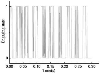
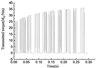
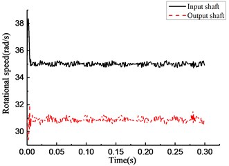
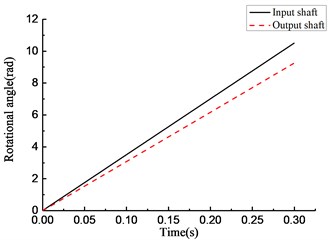
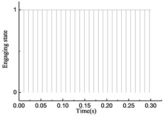
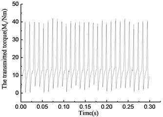
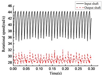
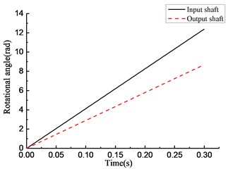
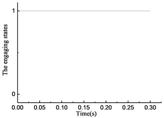
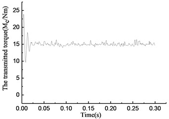
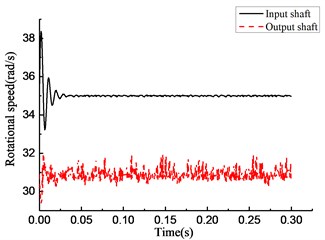
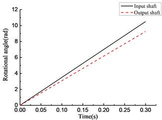
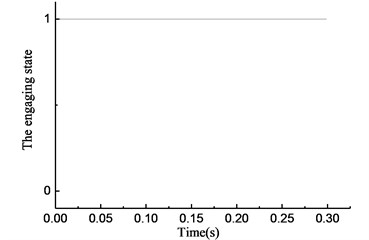
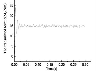
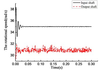
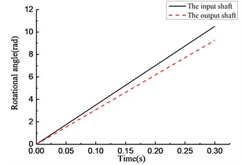
The initial velocity of the overrunning clutch is assumed to be 35 rad/s. The driving torque of the input end Ti is 15 N•m. The load torque of the output end To is –17 N·m. The results of the simulation of the rotational speed discrepancy model are shown in Fig. 4. The results of the simulation of the rotational speed discrepancy model with the angle compensation are shown in Fig. 5. The results of the simulation of the rotational angle discrepancy model are shown in Fig. 6. The results of the simulation of the rotational angle discrepancy model with the angle compensation are shown in Fig. 7. In each figure, panel (a) shows the engaging state of the overrunning clutch, panel (b) shows the torque transmitted by the clutch, panel (c) shows the rotational speed of the input shaft and output shaft, and panel (d) shows the angle between the input shaft and the output shaft. And the numerical results are shown in Table 2.
Fig. 4Simulation results of rotational speed discrepancy model under constant torque
a)
b)
c)
d)
As shown in Fig. 4(a), the y-axis plots the state of the overrunning clutch; the value 1 means engagement, and 0 means overrunning. The overrunning clutch is in engagement from 0 to 0.01 s. In the time from 0.01 to 0.3 s, the state of the overrunning clutch switches constantly. As shown in Fig. 4(b), from 0 to 0.01 s, the torque transmitted by the clutch increases linearly, and in the time from 0.01 to 0.3 s, the torque appears as a fast hopping between a positive value and 0 with the changes in the state of the overrunning clutch; the positive value also increases over time. As shown in Fig. 4(c), from 0 to 0.01 s, the rotational speed of the input end increases constantly because of the driving torque. On the contrary, the rotational speed of the output end decreases constantly because of the load torque. The overrunning clutch is in engagement at 0.01 s while the rotational speed of the input end decreases, and the rotational speed of the output end increases. After that, the rotational speed of the input and output ends tends to a relatively stable state, which fluctuates within the scope of ±0.5 rad/s. As shown in Fig. 4(d), the rotational angle of the input and output ends increases linearly over the entire process.
Fig. 5Simulation results of rotational speed discrepancy model with angle compensation under constant torque
a)
b)
c)
d)
Fig. 6Simulation results of rotational angle discrepancy model under constant torque
a)
b)
c)
d)
As shown in Fig. 5(a), the overrunning phenomenon occurs at intervals for a short time while engaging. As shown in Fig. 5(b), the torque transmitted by the overrunning clutch increases constantly while engaging and drops to 0 in a short time while the clutch switches from the engaging state to the overrunning state. As shown in Fig. 5(c), the rotational speed of the input and output end undergo a large fluctuation. As shown in Fig. 5(d), the rotational angle of the input and output end increases linearly.
Fig. 7Simulation results of rotational angle discrepancy model with angle compensation under constant torque
a)
b)
c)
d)
As shown in Fig. 6(a), the overrunning clutch keeps engaging constantly. As shown in Fig. 6(b), from the beginning of the simulation, the torque transmitted by the clutch oscillates and increases from 0, reaches 15 N·m at 0.025 s, and oscillates within the scope of ±2 N·m. As shown in Fig. 6(c), the rotational speed of the input end undergoes a large fluctuation when the clutch first engages. After that, the speed tends to be stable and oscillates slightly near 37 rad/s. The rotational speed of the output end has the same process and finally oscillates within the scope of ±0.5 rad/s near 32.5 rad/s. As shown in Fig. 6(d), the rotational angle of the input and output ends increases linearly. The simulation results shown in Fig. 7 are essentially consistent with those shown in Fig. 6.
By comparing the state of the overrunning clutch in Figs. 4(a) to 7(a), the phenomenon was found that the overrunning clutch, which model regards the rotational speed difference as the determinant to recognize the connecting state, no matter with consideration of angle compensation or without, switches between engaging and overrunning states many times throughout the process. However, the overrunning clutch, which model regards the rotational angle difference as the determinant, no matter with consideration of angle compensation or not, stabilizes the engaging state.
By comparing the torque transmitted by the clutch in Figs. 4(b) to 7(b) and Table 2, the phenomenon was found that the transmitted torques of the two rotational angle discrepancy models both fluctuate at 15 Nm within the maximum at 16 Nm, the minimum at 14 Nm after stabilization time for around 0.025 s. It means that the torques in two rotational angle discrepancy models remain as steady as driving torque and tend to a true value, which are similar to the actual situation. And the transmitted torques of the two rotational speed discrepancy models keep fluctuation as the frequent changes between engaging and overrunning states mentioned previously within the maximum at 37 Nm and 42 Nm respectively, the minimum at 0 Nm, which is contrary to the dynamic characteristic of overrunning clutch.
By comparing the rotational speed and angle of the input and output ends in Figs. 4(c) to 7(c) and 4(d) to 7(d), the phenomenon was found that, compared with the rotational speed discrepancy model, the speed of the input and output ends in the rotational speed discrepancy model with angle compensation undergoes a larger oscillation, and its angle of the input end also increases, but there is no obvious angle difference in the other three models.
Table 2Simulation results of the four models under stable driving torque.
– | Rotational speed discrepancy model | Rotational speed discrepancy model with angle compensation | Rotational angle discrepancy model | Rotational angle discrepancy model with angle compensation |
Driving torque / (Nm) | 15 | |||
Number of state switching | 89 | 58 | 0 | 0 |
Maximum value of stable transmitted torque / (Nm) | 37 | 42 | 16 | 16 |
Minimum value of stable transmitted torque / (Nm) | 0 | 0 | 14 | 14 |
3.3. Varying driving torque
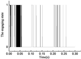
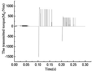
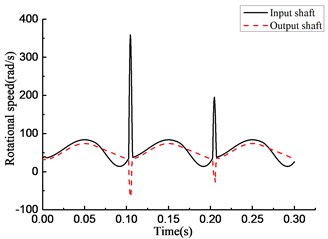
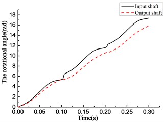
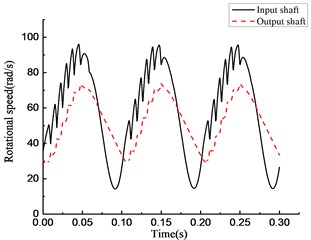
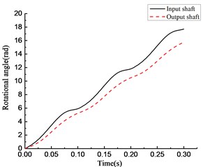
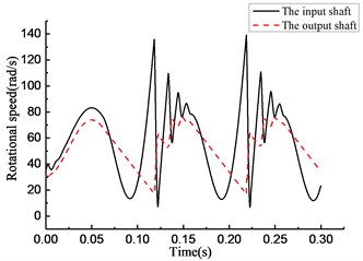
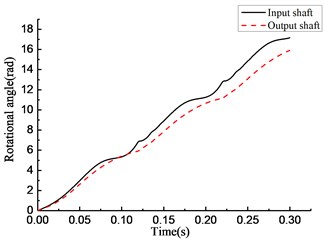
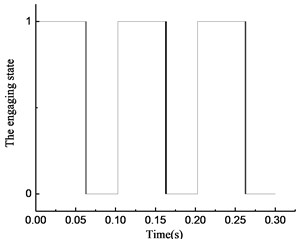
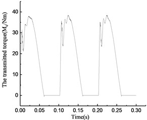
The initial velocity of the overrunning clutch was assumed to be 35 rad/s. The driving torque of the input end is expressed as Ti=15+30sin(20πt)N·m. The load torque of the output end is −17 N·m. The results of the simulation of the four model types are shown in Figs. 6 to 9. The numerical results are shown in Table 3.
As shown in Fig. 8(a), the overrunning clutch is in engagement from 0 to 0.01 s. In the time period from 0.01 to 0.065 s, the state of the overrunning clutch switches constantly. The clutch keeps overrunning from 0.065 to 0.1 s. The clutch repeats the previous action in the next 0.2 s. As shown in Fig. 8(b), in the time period from 0 to 0.065 s, 0.1 to 0.165 s, and 0.2 to 0.265 s, the torque transmitted by the clutch undergoes fast hopping between a positive value to 0 with switching the state of the overrunning clutch, and the positive value can reach 500 N·m or more within the time from 0.1 to 0.165 s and 0.2 to 0.265 s, and a negative value appears near 0.1 s and 0.2 s. As shown in Fig. 8(c), the rotational speed of the input end fluctuates with the torque variation, and within the time from 0.065 to 0.1 s, 0.165 to 0.2 s, and 0.265 to 0.3 s, the rotational speed of the input end is lower than that of the output end; that means that the clutch is in overrunning state that time. At the moment of 0.1 s and 0.2 s, a large positive hop appears in the rotational speed of the input end while a large negative hop appears in the rotational speed of the output end. Fig. 8(d) shows that the rotational angle of the input and output end increases linearly.
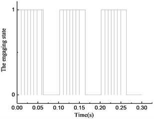
It can be seen from Fig. 9(a), despite a few momentary overrunning instances, the overrunning clutch is in engagement during most of the time from 0 to 0.065 s. In the time period from 0.065 to 0.1 s, the clutch is in the overrunning state. The clutch repeats the previous action after that. As shown in Fig. 9(b), the torque transmitted by the clutch increases when the state switches from overrunning to engaging, and drops to 0 when the state switches from engaging to overrunning. In the time period from 0.065 to 1 s, the torque is 0 because the clutch is in the overrunning state. As shown in Fig. 9(c), a serrated fluctuation appears in the rotational speed of the input and output end from 0 to 0.065 s, and the rotational speed of the input end is lower than that of the output end. As shown in Fig. 9(d), the rotational angle of the input and output ends increases linearly.
Fig. 8Simulation results of rotational speed discrepancy model under varying torque
a)
b)
c)
d)
Fig. 9Simulation results of rotational speed discrepancy model with angle compensation under varying torque
a)
b)
c)
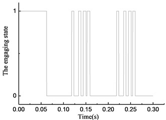
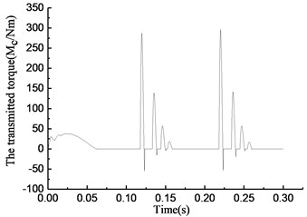
Fig. 10Simulation results of rotational angle discrepancy model under varying torque
a)
b)
c)
d)
Fig. 11Simulation results of rotational angle discrepancy model with angle compensation under varying torque
a)
b)
c)
d)
Fig. 10(a) shows that the overrunning clutch is in engagement from 0 to 0.065 s and switches to the overrunning state from 0.065 to 0.12 s. The alternations between engaging and overrunning appear from 0.12 to 0.16 s. Then, the clutch is in overrunning state from 0.16 to 0.22 s. After that, the clutch repeats the steps from 0.12 to 0.22 s. As shown in Fig. 10(b), the torque transmitted by the clutch is approximately 50 N·m when the clutch first engages in the time period from 0 to 0.065 s. A large positive torque occurs with the switches from overrunning to engaging in the time period from 0.12 to 0.16 s and 0.22 to 0.26 s, and the torque increases with increasing engaging time. A negative torque occurs with the switches from engaging to overrunning. As shown in Fig. 10(c), the rotational speed of the input end fluctuates with the torque variation, and the rotational speed of the output end is also normal from 0 to 0.12 s. The large fluctuation occurs in the rotational speed of the input and output ends when the state of the clutch switches from overrunning to engaging in the time period from 0.12 to 0.16 s and 0.22 to 0.26 s. As shown in Fig. 10(d), the rotational angle of the input and output ends increases linearly.
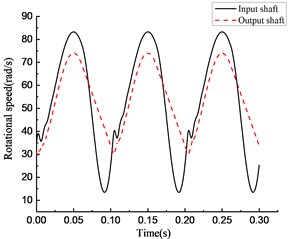
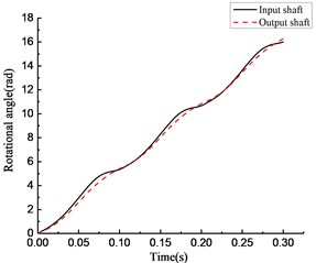
As shown in Fig. 11(a), the clutch keeps engaging from 0 to 0.065 s, and the transient switching between engaging and overrunning appear near 0.065 s. Then, the clutch is in the overrunning state from 0.065 to 0.1 s. After that, the clutch repeats the steps from 0 to 0.1 s. As shown in Fig. 11(b), the torque transmitted by the clutch first increases then decreases in the time period from 0 to 0.065 s, and it becomes 0 in the time period from 0.065 to 0.1 s. As shown in Fig. 11(c), the rotational speed of the input and output ends changes with increasing torque. The rotational speed of the input end decreases rapidly, and its speed decreases even faster than that of the output end because of the negative torque value in the time period from 0.065 to 0.1 s. Because of the stiffness damping characteristic of the clutch, a tiny fluctuation of the rotational speed occurs with switching from overrunning to engaging at approximately 0.1 s. As shown in Fig. 11(d), the rotational angle of the input and output ends increases linearly.
By comparing the state of the overrunning clutch in Figs. 8(a) to 11(a), the phenomenon was found that with the variation in transmitted torque, there are many instances of switching between the overrunning and engaging modes in the four models. For positive values of transmitted torque in the rotational speed discrepancy model, rotational speed discrepancy model with angle compensation, and rotational angle discrepancy model, the switching phenomenon occurs. In the rotational angle discrepancy model with angle compensation, when the value of the transmitted torque is positive, the clutch remains in the engaging state and switches to the overrunning state when the value turns negative.
By comparing the torque transmitted by the clutch in Figs. 8(b) to 11(b) and Table 3, the phenomenon was found that the maximum values of transmitted torque of the two models without angle compensation are 953 Nm and 297 Nm respectively, which are much larger than that of the two models with angle compensation, while the driving torque fluctuate in a smaller range where the maximum is 45 Nm and the minimum is –15 Nm.
Table 3Simulation results of the four models under varying driving torque
– | Rotational speed discrepancy model | Rotational speed discrepancy model with angle compensation | Rotational angle discrepancy model | Rotational angle discrepancy model with angle compensation |
Driving torque / (Nm) | 15+30sin(20πt) | |||
Number of state switching | 429 | 24 | 17 | 3 |
Maximum value of transmitted torque / (Nm) | 953 | 90 | 297 | 38 |
Minimum value of transmitted torque / (Nm) | –1529 | 0 | –55 | 0 |
And the minimum values of transmitted torque of the two models without angle compensation are negative, which are contrary to the characteristic of the clutch. A high-frequency and wide-amplitude fluctuation appears in the rotational speed discrepancy model with angle compensation, while the rotational speed discrepancy model with angle compensation transmits torque in the fluctuation period of 0.1 s in a smoother way, which is more similar to the actual situation.
By comparing the rotational speed and angle of the input and output ends in Figs. 8(c) to 11(c) and 8(d) to 11(d), the phenomenon was found that a sudden change of the rotational speed appears in the models without angle compensation considered, and a serrated fluctuation appears with the high-frequency and wide-amplitude fluctuation of the transmitted torque in the rotational speed discrepancy model with angle compensation. However, the rotational angle discrepancy model with angle compensation performs better.
4. Comparison and analysis of experiment
By comparing the simulation results under stable and varying driving torques, we made a preliminary judgment that the rotational angle discrepancy model with angle compensation can more accurately describe the dynamic characteristics of the overrunning clutch. To verify this judgment, a transmission experiment platform of the overrunning clutch-single gear pair system was built. The platform consists of a driving motor, overrunning clutch-single gear pair system, inertia component, load, corresponding controller, and measuring equipment. The experimental setup is shown in Fig. 12, and the parameters of the components are shown in Table 4.
Fig. 12Transmission experimental platform of overrunning clutch-single gear pair system

Table 4Component parameters of experimental platform
Item | Model | Parameters | Values |
Three-phase asynchronous motor | 1TL0001-0EB4 | Rated power | 1.5 kW |
Magnetic powder brake | FZ 10.J | Maximum torque capacity | 10 N·m |
Rotational inertia | – | Motor | 0.0047 kg·m2 |
– | Inertial flywheel 1 | 0.0224 kg·m2 | |
– | Inertial flywheel 2 | 0.0224 kg·m2 |
On the platform, the experiment was carried out under stable and varying driving torques; the data was collected after the platform had been working for a while in a stable state. Corresponding to the stable state in the experiment, we compared the rotational speed after 0.05 s in the four models with the data collected from the platform. Because the transmission ratio of the overrunning clutch-single gear pair system was 17/15, in order to facilitate the comparison and analysis, we multiplied the rotational speed of the output end from the experiment and simulation by that ratio. The experimental results after treatment are shown in Figs. 11 and 12. The simulation results are shown in Figs. 13 and 14.
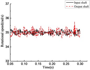
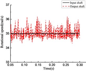
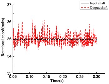
As shown in Fig. 13, under the stable driving torque, the rotational speeds of the input and output ends are both stable at 750 rpm and fluctuate in the range of ±50 rpm because of the vibration of the platform. As shown in Fig. 15, under the same torque, the speed curves simulated from the rotational speed discrepancy model, rotational angle discrepancy model, and rotational angle discrepancy model with angle compensation are closer to the experimental results. In the rotational speed discrepancy model with angle compensation, the speed fluctuation is larger, and an obvious rotational speed difference between the input end and the output end exists, meaning that the simulation results are different from the experiment.
Fig. 13Experimental results of rotational speed of input and output shafts under constant torque
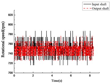
Fig. 14Experimental results of rotational speed of input and output shafts under varying torque
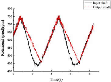
Fig. 15Simulation results of rotational speed of four models under constant torque
a)
b)
c)
d)
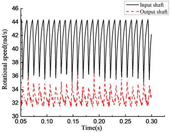
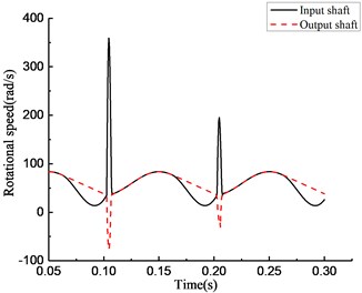
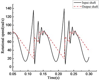
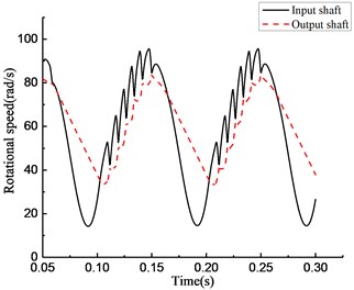
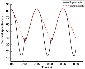
As shown in Fig. 14, under the varying driving torque, the speed of the input end is obviously lower than that of the output end in the time period from 1 to 3 s and from 5 to 7 s; that means the clutch is in the overrunning state. In Fig. 16, in the rotational speed discrepancy model shown in panel (a), large speed fluctuations occur in the input and output ends when the state of the clutch switches from overrunning to engaging in the time period from 0.1 to 0.2 s; that means the simulation result is different from the experiment. In the rotational angle discrepancy model shown in panel (b), the large speed fluctuation also occurs in the input end with switching from overrunning to engaging at the same time. This means that the simulation result is different from the experiment in this case as well. In the rotational speed discrepancy model with angle compensation shown in panel (c), a high-frequency and wide-amplitude fluctuation appears in the input end and the output end when the rotational speed increases; that means the simulation result is different from the experiment in this case as well. The trend of the change in the rotational angle discrepancy model with angle compensation agrees well with the experiment. The result of the experiment verifies the preliminary judgment mentioned previously.
Fig. 16Simulation results of rotational speed of four models under varying torque
a)
b)
c)
d)
5. Conclusions
By comparing the results of the simulation and experiment mentioned above, the conclusion was drawn as bellow: the rotational speed discrepancy model could not describe the actual working state of the overrunning clutch accurately, because the frequent switching phenomenon appeared in the simulation result, which leaded to a high-frequency and wide-amplitude fluctuation in the result of transmitted torque, and it did not agree with the experiment result. Also, the rotational angle discrepancy model can only accurately describe the actual working state under constant torque, because the amplitude of the transmitted torque is large, and the obvious negative value appears to be in conflict with the clutch characteristics.
The research showed that the rotational angle discrepancy model with angle compensation, which had taken the influence of dynamic characteristics of the self-lock components into account, could accurately describe the actual working state under both the varying torque and constant torque, as well as the dynamic characteristics of the transmission system with overrunning clutch.
References
-
Valium S., Keller A., Alyukov A. Design and calculating of relay-type overrunning clutch. SAE World Congress and Exhibition, Detroit, U.S.A, 2016.
-
Zhang B., Hou Q., Li X., Xu G., Zhu Y., Zhang B., et al. Research on overrunning clutch speed coupling control strategy in a parallel plug-in hybrid electric vehicle. Energy Procedia, Vol. 17, 2010, p. 492-498.
-
Balaji R., Mockensturm E. M. Dynamic analysis of front-end accessory drive with decoupler/isolator. International Journal of Vehicle Design, Vol. 39, Issue 3, 2005, p. 208-231.
-
Zeng X. K., Shangguan W. B., Zhang S. F. Rotational vibration modeling and parameters optimization design of engine front end accessory drive system with overrunning alternator decoupler. Transactions of CSICE, Vol. 30, Issue 2, 2012, p. 179-185.
-
Huang H., Huang J. Application of robust design philosophy to overrunning clutch design. Mechanical Science and Technology for Aerospace Engineering, Vol. 28, Issue 8, 2009, p. 1-7.
-
Hild M., Siedel T., Geppert T. Design of passive, bidirectional overrunning clutch for rotary joints of autonomous robots. Intelligent Robotics and Applications, Vol. 7101, 2011, p. 397-405.
-
Li Z. H., Yan H. Z., Cao Y. M. Design and analysis of logarithmic spiral type sprag one-way clutch. Journal of Central South University, Vol. 22, Issue 12, 2015, p. 4597-4607.
-
Vernay P., Ferraris G., Delbez A., Ouplomb P. Transient behavior of sprag-type over-running clutch: experimental study. Journal of Sound and Vibration, Vol. 248, Issue 3, 2001, p. 567-572.
-
Chen L. W., Chen Y. C. Wedge-shaped track design and contact analysis of overrunning clutches. Drive System Technique, Vol. 222, Issue 9, 2010, p. 1647-1656.
-
Ma W. X., Hu J., Chu Y. X., Wang S. L., Wu Y. S. Dynamic load strength analysis of over-running clutch of dual turbine torque. Journal of Jilin University, Vol. 44, Issue 3, 2014, p. 675-679.
-
Gill-Jeong C. Nonlinear behavior analysis of spur gear pairs with one-way clutch. Journal of Sound and Vibration, Vol. 301, Issue 3, 2007, p. 760-776.
-
Zhu F., Parker R. G. Non-linear dynamics of one-way clutch in belt-pulley systems. Journal of Sound and Vibration, Vol. 279, Issue 1, 2005, p. 285-308.
-
Ding H., Zu J. W. Effect of one-way clutch on nonlinear vibration of belt-drive systems with continuous belt model. Journal of Sound and Vibration, Vol. 332, Issue 24, 2013, p. 6472-6487.
-
Kong X., Xiong P., Nie S. Simulating dynamic characteristics of retainer-roller-eccentric arc type overrunning clutch with ADAMS and ANSYS. Mechanical Science and Technology for Aerospace Engineering, Vol. 31, Issue 2, 2012, p. 317-249.
-
Yu F., Li Y., Sun D., Shen W. Analysis of dynamic characteristic of automobile transmission gearbox. Research Journal of Applied Sciences Engineering and Technology, Vol. 5, Issue 4, 2013, p. 1449-1453.
-
Mockensturm E. M., Balaji R. Piece-wise linear dynamic systems with one-way clutches. Journal of Vibration and Acoustics, Vol. 127, Issue 5, 2005, p. 475-482.
-
Ming-Sheng H. E., Yan H. Z. Simulation of effects of radial installation error on engagement properties of sprag clutch. Computer Engineering and Design, Vol. 31, Issue 22, 2010, p. 4897-4900.
-
Sorniotti A., Holdstock T., Pilone G. L., Viotto F., Bertolotto S., Everitt M., et al. Analysis and simulation of the gearshift methodology for novel two-speed transmission system for electric power trains with central motor. Proceedings of the Institution of Mechanical Engineers Part D Journal of Automobile Engineering, Vol. 226, Issue 7, 2012, p. 915-929.
-
Zhao K., Liu Y., Huang X., Yang R., Wei J. Uninterrupted shift transmission and its shift characteristics. IEEE/ASME Transactions on Mechatronics, Vol. 19, Issue 1, 2014, p. 374-383.
-
Ye J., Zhao K., Liu Y., Huang X., Lin H. Multi-stage global trajectory optimization for the overlapping shift of seamless two-speed transmission using Legendre pseudo-spectral method. Advances in Mechanical Engineering, Vol. 9, Issue 12, 2017. https://doi.org/10.1177/1687814017741737.
Cited by
About this article
The authors disclosed the receipt of the following financial support for the research, authorship, and/or publication of this article: This work was supported by the National Natural Science Foundation of China, No. 51575189.
