Abstract
In order to diagnose the abnormal sound fault of the diesel without disassemble, dual microphones are used to collect noise signal of the engine in this paper, and the sound pressure signal is decomposed with wavelet decomposition technique. By comparing different wavelet decomposition techniques, it determines the sound feature parameter for fault diagnosis, and establishes a BP neural network for pattern recognition. The test result shows that diagnosing engine fault with dual microphones is accuracy, and it can be applied to diagnose the abnormal sound fault of engine.
1. Introduction
Because of the low signal-to-noise ratio, the feature of acoustic signals is more difficult to be extracted. For the problem of low signal-to-noise ratio, many researchers have carried out some research, such as using wavelet analysis, applying wavelet transform to the processing of acoustic signals for rolling bearing failure [1], and improving the signal-to-noise ratio of acoustic signals through multi-scale decomposition [2]; using independent component analysis and autocorrelation analysis of noise reduction [3]; the use of morphological component analysis method for generalized soft threshold decrease noising [4]; and the use of MEL frequency inverse spectral coefficient algorithm to extract fault features [5]. These noise reduction methods achieve better results under the condition that the sound source environment is single.
However, these existing studies are only the types of faults with obvious diagnostic characteristics. In practice, most of the engine faults are gradual processes from light to heavy (for example, slight oil leakage to complete oil shutoff), while it's useful that minor faults are diagnosed.
For acoustic signals, analyzing the frequency domain is more effective than the time domain because the more important characteristics are mainly reflected in the power spectrum, and the spectrum is not easily affected by external interference, and the acoustic characteristics are relatively stable.
This article mainly analyzes the low frequency signal of the engine. Based on multi-resolution analysis and band energy analysis, combined with the strong ability of neural network in nonlinear mapping processing, this paper presents a method of engine fault diagnosis using dual-microphone measurement combined with wavelet multi-resolution analysis.
2. Signal processing and pattern recognition method
2.1. Wavelet multiresolution analysis
According to the characteristics of engine noise signal, this paper uses wavelet multi-resolution analysis method to deal with engine noise signal. The time-frequency resolution of the wavelet transform varies with the time decomposed scale. For the low-frequency component of the signal, the time resolution is higher, and the frequency resolution is lower. For the high-frequency component of the signal, the time resolution is lower, and the frequency resolution is higher. S. Mallat proposed the concept of multi-resolution analysis when constructing orthogonal wavelet bases, and was first applied to wavelet analysis. Wavelet analysis is also mature in the field of fault diagnosis at the present stage [6-8]. The multiresolution analysis wavelet decomposition tree is shown in Fig. 1.
Fig. 1Four-layer multiresolution analysis tree structure
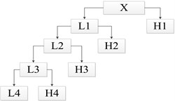
(X is the signal to be analyzed; L1-L4 is the low-frequency part of 1-4 layers in sequence; H1-H4 is the high-frequency part of 1-4 layers in sequence)
If the highest frequency is f, the frequency range for the high-frequency H1 signal is [f/2, f], and the low-frequency L1 frequency range is [0, f/2]. When the second layer is decomposed, the high frequency portion H1 obtained by the decomposition of the original first layer is not decomposed, only the low frequency portion L1 is decomposed, and so on, the signal is decomposed layer by layer. After the signal X is decomposed by the four-layer multiresolution shown in the figure, the signal coefficients (i= 1, 2, 3, 4) can be obtained, and the corresponding frequency ranges are [0, f/16), [f/16, f/8), [f/8, f/4), [f/4, f/2), [f/2, f]. That is, signal X has the following equation:
Since the energy of the time-domain calculation signal is equal to the energy value calculated in the frequency domain, each band energy is Ei, and the feature vector is constructed:
If E=∑Ei, then normalized eigenvector is:
Fig. 24-layer wavelet decomposition results
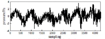
a) Engine duty cycle signal
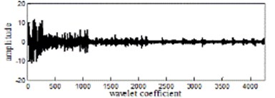
b) After 4-layert wavelet decomposition
As shown in Fig. 2, the amplitude of the frequency band coefficient of the acoustic signal of the engine after multi-resolution analysis is obviously different, and five waveform segments with different amplitudes can be clearly seen.
2.2. Band energy accumulation feature extraction
According to the wavelet decomposition results, characteristic parameters are obtained by calculating the band energy accumulation. The wavelet-band energy accumulating method mainly analyzes the time-frequency transform of the signal and decomposes it into different frequency bands, performs statistical analysis on the total energy in each frequency band, judges the change of the fault signal with the change of the energy in the band, and uses these characteristic changes to establish the signal. The mapping relationship between frequency band energy and engine abnormal noise status.
The preliminary analysis of the acoustic signal of the engine shows that the Daubechies family of wavelet basis functions db4 or db5 and the number of decomposition layers 3, 4, and 5 (energy bands 4, 5, and 6) can achieve better results. Comprehensive analysis of normal conditions, normal oil leakage, slight oil leakage, moderate oil leakage, and complete oil breakage (misfire failure), as shown in Fig. 4. The length shown in each band is the proportion of the corresponding band to the total band energy. The abscissa is the percentage of the total energy in each frequency band, and the ordinate is the four fault conditions after wavelet decomposition. From the figure, it can be found that when the number of decomposition layers is 3, the energy characteristics of the frequency band of slight oil leakage failure and moderate oil leakage failure are completely indistinguishable, and when the number of decomposition layers is 5, the stability of the band energy characteristics is poor. From the comparison of (a)-(f) in Fig. 4, when the number of decomposition layers is 4 and the wavelet basis function is db4, the fault condition is better differentiated and the stability of the same state feature is better. In this paper, the fault eigenvectors are established by the wavelet basis function db4 on the 10 frequency bands obtained by performing 4-layer wavelet decomposition on the two microphone acoustic signals.
Fig. 3Analysis diagram of different wavelet decomposition layers and basis function bands: (s1: Complete oil failure, s2: Moderate oil leakage, s3: Light oil leakage, s4: Normal operating conditions)
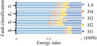
a) Wavelet decomposition layer4(db5)
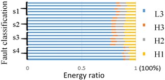
b) Wavelet decomposition layer3(db5)
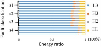
c) Wavelet decomposition layer5(db5)
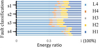
d) Wavelet decomposition layer3(db4)
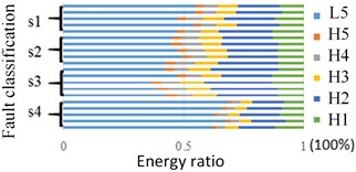
e) Wavelet decomposition layer4(db4)
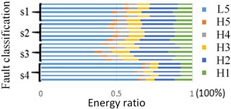
f) Wavelet decomposition layer4(db5)
2.3. Constructing BP neural network
BP neural network has powerful nonlinear mapping, self-learning and self-adaption, generalization and fault-tolerant capabilities, mainly composed of input layer, hidden layer and output layer. If the sample output goes to S=[s1,s2,s3,s4], and the training result vector is R=[r1,r2,r3,r4], then the square error between the network training results and the target output of a single sample is:
Thus, training system error mean:
where k is the number of samples, we can obtain the weight correction amount ∆ and of the hidden layer and the output layer by the value of , and then obtain the network weight correction relationship:
The structure of the BP algorithm is shown in Fig. 4, where (1), (2), ..., are the input values of the network, and (1), (2), ..., are the predicted values of the network. The input values of the network propagate from the input layer through the hidden layer to the output layer, and the input responses of the network are obtained by each neuron in the output layer. Then, in order to reduce the direction of the target output and the actual error, each connection weight value is corrected layer by layer from the output layer through each intermediate layer, and finally returns to the input layer. Within a certain range, with the back propagation of the error, the accuracy of the feedback of the network test also increases. Through the two processes of forward propagation and backward propagation, the algorithm advances and the error is constantly corrected, and the output value approaches the ideal value.
Fig. 4BP neural network structure
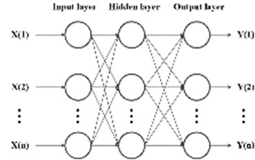
The eigenvectors composed of the normalized frequency band coefficients are the input values of the BP neural network, and the network outputs correspond to the four working condition setting codes. The failure type (V) is set as the normal oil (1000), slight oil leakage (0100), moderate oil leakage (0010) and complete oil cut (0001), which supply according to the severity of “oil leakage”.
3. Fault diagnosis experiment
3.1. Data collection and processing
The experiment used a 40 PH type microphone from GRAS, and its operating frequency was 10-20 kHz. Integrated error intensity measurement mechanism, combined with experimental conditions, take the microphone measurement position from the noise source about 0.8 m, the specific location shown in Fig. 6, 1 for the single sound pressure measurement microphone, numbered 1 and 2 The microphone is a microphone set for measuring double sound pressure. The experimental sampling frequency is 25.6 kHz. We take the Weichai WD615 six-cylinder engine as the experimental object, set the high-pressure tubing oil leakage fault, and use the NI data acquisition system to collect acoustic signals. The engine speed is 710 r•min-1.
Fig. 5Microphone measurement position

By adjusting the amount of fuel injected into the cylinder by the high pressure fuel pipe of the sixth cylinder to simulate the oil leakage fault, which included the high pressure fuel pipe, the normal working condition, slight leaking condition, moderate leaking condition and completely broken condition. Fixed sound signal acquisition device (microphone), two microphones simultaneously measure the acoustic signal of the engine under four operating conditions, the sampling time for each working condition is 5 s, 5 sets for each sample.
The wavelet base function db4 is used to decompose the acoustic signal into four layers to obtain five frequency band coefficient values, namely the wavelet coefficient S1 of the high frequency signal and the low frequency wavelet coefficients S2, S3, S4, S5. After summing the wavelet coefficients of the signals of the five frequency bands obtained by decomposing the acoustic signal, they are summed and further normalized to obtain as a characteristic parameter of the signal. Therefore, for a single microphone feature vector, there are:
For dual microphone feature vectors:
Pattern recognition of the energy band characteristic parameters of four different working conditions, 500 working cycles (feature vectors) collected by the microphone under each working condition are divided into sample data and test data, among which 400 groups are randomly selected for BP neural network samples Training, another 100 groups as test samples.
3.2. BP network structure training and results
When the BP neural network is used for experimental analysis, since the experiment includes four conditions of normal engine oil supply, slight oil leakage, moderate oil leakage, and complete oil cutoff, the type of sample to be classified is 4, and the number of nodes corresponding to the output layer is also It is determined as 4 accordingly. According to the Kolmogorov theorem, the number of neurons in the hidden layer m and the number of neurons in the input layer and the optimal range of the output layer nodes are: where is in the range of 1 to 10. After repeated experiments, the number of neurons in the hidden layer is set to 9 to obtain better results. The neuron transfer function selects the tangent S-shaped transfer function, the training function selects the LM algorithm, the learning function selects the gradient descent momentum learning function, and the network performance function is the mean squared error function. After many experiments, the learning rate is set to 0.001 for better training. The effect is that the maximum number of iterations is 600.
Under the same conditions, using BP to extend into the network and fuzzy clustering for pattern recognition, the results are shown in Table 2. From the Table, it can be found that with the same algorithm, dual microphones are superior to single microphones in terms of diagnostic accuracy. After many experiments, the average training time of the BP neural network is about 2 seconds, and the fuzzy clustering training time is about 10 seconds. Therefore, the BP neural network is selected as the fault identification method.
Table 1Comprehensive analysis of network training
Number of microphones | Pattern recognition method | Average accuracy/% | Wrong distribution area | Training time/s |
Dual | BP neural network | 92 | Mild5, Moderate3 | 2.767 |
Fuzzy clustering | 91 | Mild3, Moderate5, Severe1 | 3.417 | |
Single | BP neural network | 73 | normal3, Mild11, Moderate12, Severe1 | 9.113 |
Fuzzy clustering | 66 | normal12, Mild12, Moderate9, Severe1 | 1.653 |
4. Conclusions
By selecting the wavelet basis function and the number of decomposition layers, using two microphones to collect engine acoustic signals, and adopting the method of wavelet multi-resolution analysis combined with BP neural network to diagnose diesel engine faults, good results are obtained, as follows:
(1) For engine acoustic signals, the wavelet basis function db4 can well decompose the low-frequency part of the acoustic signal and can extract obvious fault features.
(2) Using dual microphones to collect sound pressure signals, combined with BP neural network to diagnose abnormal engine noise, compared with a single microphone, can greatly improve the diagnostic accuracy and diagnostic efficiency, provided a reference for engine abnormal noise diagnosis.
References
-
Wang Xiaolong, Tang Guiji. A new method for early fault diagnosis of rolling bearings based on continuous wavelet transform. Propulsion Technology, Vol. 37, Issue 8, 2016, p. 1431-1437.
-
Pan Yi, Liu Xiong, Yan Zijian. Intelligent fault diagnosis of rolling bearings based on wavelet packet band energy characteristics and BP Neural network. Automation and Instrumentation, Vol. 5, 2015, p. 82-84.
-
Yao J., Xiang Y., Qian S., et al. Noise source identification of diesel engine based on variational mode decomposition and robust independent component analysis. Applied Acoustics, Vol. 116, 2017, p. 184-194.
-
Guo Yingying, Zhang Chunliang, Yue Xia, et al. Application of morphological component analysis of acoustic signals in bearing fault diagnosis. Mechanical and Electrical Engineering Technology, Vol. 45, Issue 4, 2016, p. 55-61.
-
Kemalkar A. K., Bairagi V. K. Engine fault diagnosis using sound analysis. International Conference on Automatic Control and Dynamic Optimization Techniques (ICACDOT), 2016, p. 943-946.
-
Ma S., Wang H. Based on wavelet packet and the LS-SVM ship with warship engine fault diagnosis. Control and Decision Conference (CCDC), Vol. 2016, 2016, p. 2687-2691.
-
Qu J., Zhang Z., Gong T. A novel intelligent method for mechanical fault diagnosis based on dual-tree complex wavelet packet transform and multiple classifier fusion. Neurocomputing, Vol. 171, 2016, p. 837-853.
-
Liu Qing, Zhu Bing An. Fault diagnosis of gearbox based on wavelet analysis. Mechanical Design and Manufacture, Vol. 11, 2016, p. 245-248.

