Abstract
As an essential part of optical system, lens hoods consisting of shells and plates are designed mainly to protect optical system from unexpected light. Except for such basic function, the hood proposed in this paper has to load several subassemblies and will be applied in high-resolution and wild field-of-view space camera with strict mass limitation, which makes effective mechanical reinforcement and lightweight of hood quite necessary. To meet such requirements, stiffness improvement methods is promoted in this paper to help improve the constraint fundamental frequency and decide the areas where subassemblies can be placed. Subsequently, optimization on key sizes of the hood proceeds to achieve a higher fundamental frequency and a lower weight. Finally, a prototype is fabricated based on the optimal design and a sweep test is held to verify the analytical fundamental frequency. The prototype has large external dimensions (1960×1640×2055 mm) but weighs only 33.5 kg when loading several subassemblies which totally weight 15.95 kg. Sweep test indicates that experimental constraint fundamental frequency is 36.82 Hz. All the parameters coincide with that of theoretical design well. The whole work of this paper provides a worthwhile method to the design of lens hood with large external dimensions and high specific stiffness in space camera. Since the lens hood is a typical plate and shell structure, the method, design and optimization process in this paper may also be helpful to the plate and shell structure in which stiffness and lightweight are highly required.
1. Introduction
Lens hood, which is mainly used to protect optics from unwanted light, plays an indispensable role in space camera. For the optical remote sensing satellite with high resolution and Wild Field-Of-View (WFOV) researched in this paper, the design of lens hood becomes more complicated. Owing to the expensive launching cost and extreme launching condition, lightweight and stiffness improvement become higher demanded [1, 2]. However, lightweight and stiffness are on the contrary to each other since increment of one will always lead to decrement of the other, so reasonable balance between them two becomes a challenging work.
The lens hood usually employs two typical forms. The first type integrates the hood and support structure, it is comparatively small and commonly seen in small and medium space camera since it will be comparatively easy to fabricate and to satisfy the optical and mechanical requirements when applying on such space camera. For example, the carbon fiber composite framework for small lightweight space camera designed by Shuai Yang et al., applies such type and it can be regarded as support structure as well as lens hood [3]. The second type is only used for light-shading and usually made up of thin Carbon Fiber Reinforced Polymer (CFRP) shells and plates. The hood researched in this paper belongs to this type. Generally speaking, hoods of such type are commonly applied in optical systems which maintain large external dimensions. They are usually flexible since they are not designed to support anything. However, the hood researched in this paper is required to load subassemblies (totally weight 15.95 kg) and weights no more than 33 kg, so stiffness becomes more required to ensure no only the hood’s but also the subassemblies’ safety during extreme launching condition.
Former researches mostly concerned about the optical performances of lens hood. e.g., Moldabekov M. et al. developed a new approach for optical head of the star tracker and its hood for satellites to meet optical requirement of Kazakhstan’s satellites [4]. Yan Peipei et al. from Xi’an Institute of Optics and Precision Mechanics optical system applied stray light elimination to design a lens hood for three-mirror optical system [5]. Zhong-Shu Chiang et al. applied Point Source Transmittance (PST) to evaluate the shielding efficiency of a lens hood and achieved a standard for a two stage lens hood [6]. Generally speaking, former researchers cared more about the optical feasibility of the hood while mechanical feasibility was less concerned because the hoods mentioned above are not required to load heavy subassemblies.
Considering particularities of the hood researched in this paper, this paper takes mechanical feasibility more seriously than ever. A stiffness improvement method is promoted to help reinforce hood, improve the fundamental frequency and decide how to place all satellite subassemblies. As a result, the final constraint fundamental frequency is improved 2.4 times and the weight decreases 11 kg compared with initial structure. The whole work of this paper provides a worthwhile method to design of lens hood in space camera as well as design and optimization of structures which are made of shell and plate.
The following sections (Section 2-5) present details of the work in this paper. Section 2 mainly elaborates the design of initial structure of the lens hood and corresponding design basis. Section 3 mainly focuses on redesign and reinforce of the initial structure, stiffness improvement methods is promoted in this section to help accomplish the task and decide the placement of satellite subassemblies. Section 4 expounds an optimization which aims at lightening the hood and further improving its natural frequency, final structure of the hood is achieved in this section. Section 5 introduces the detail of sweeping test and the results of the test coincide with the analytical results well.
2. Initial lens hood
2.1. Initial lens hood structure design
Since light-shading ability is the main optical requirement for lens hood, features of optics and light path are mainly concerned during initial lens hood structure design. Taking assembly interference and machinability into account as well, the basic lens hood structure is carried out and given in Fig. 1.
CFRP is applied to manufacture the whole lens hood since it has higher specific stiffness and specific strength compared with most metallic materials. What is more, CFRP can be applied in some complicate structure due to its special filament winding technology [7]. In this paper the chosen CFRP is T700 whose elasticity modulus is 50 GPa and Poisson’s ratio is 0.3. At last, the initial structure has an external dimension of 1960×1640×2055 mm.
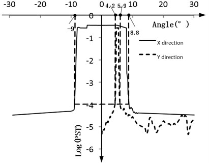
Stray light analysis has confirmed validity of this structure. Fig. 2 shows that most stray light out of view field Y: 4.2°–5.9°, X:–9.0°–8.8° has a PST lower than 10e-4. The required view field of the optical system is 4.7°–5.4° along Y and –7.9°–7.9° along X, thus the result satisfies demand of optical system in the view field. However, mechanical performance is ignored at this stage.
Fig. 1Semisectional view of initial lens hood and optic assemblies
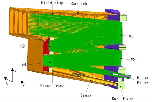
Fig. 2PST curve of initial lens hood
2.2. Analysis of initial structure
Finite Element (FE) model of the lens hood is built in HYPERMESH and the initial thickness of the whole hood is set at 1.5 mm for the normal modes analysis, the constraint fundamental frequency (the bottom assembled on back frame is constrained to simulate working state) of hood is only 14.8 Hz and the initial hood weights 44 kg, which indicates that the whole hood structure is too flexible. Since several devices which weight 0.5-2 kg will be considered to assemble on the lens hood, too flexible structure may lead to catastrophic destruction to both hood and subassemblies during extreme lunching process. Therefore, stiffness increment for the whole initial lens hood structure should proceed next.
3. Redesign and reinforce of initial structure
It is a challenge to redesign and reinforce the initial structure without big changes. Generally speaking, fundamental frequency can reveal how stiff the whole structure is, therefore, redesign and reinforcement center on how to improve fundamental frequency in this paper.
3.1. Stiffness improvement methods
It is well known that a certain continuum structure is actually an infinite multiple-degree of freedom system. FEM method is an approximate assumption which changes such infinite-degree-of-freedom system into a finite multiple-degree of freedom system [8]. The approximate analysis model for a structure with n degree can be described as:
where M stands for mass matrix, C stands for damping matrix, K stands for stiffness matrix, F stands for external load and x stands for displacement. M, C, K are n×n symmetrical matrixes while x and f are n×1 arrays.
The ith mode ϕi and frequency ωi is determined by equations below [9]:
where λi=ω2i and select ϕiwhich makes ϕTiMϕi= 1, besides, let λ1≤λ2≤…≤λn.
We assume tiny increment is given in mth rows and mth columns of matrices K and M which can be described as ∆K and ∆M, corresponding tiny changes of λi and ϕi can be described as ∆λi and ∆ϕi. The changed model can be described as:
where:
Taking Eq. 4(a)-4(d) into Eq. (3) and neglecting second and third terms gives:
Premultiplication of Eq. (5) by ϕTi gives [10]:
Since each mode is linear independent, Δϕi can be described by mode space ϕ(ϕ=[ϕ1,ϕ2,…,ϕn]) as:
Considering that ϕi and ϕj(i≠j) are orthogonal with respect to M and K:
Substitution Eq. (8) into Eq. (7) gives:
Since tiny increment is only given in mth rows and mth columns of matrices K and M, which means:
Substitution Eq. (10) into Eq. (9) gives:
-ϕmi(∆Kmm-λi∆Mmm)ϕmi.
Obviously, K', M' should both be symmetrical matrixes in regard to corresponding changed structure and at most time matrix M and M' are diagonal matrixes in FEM analysis, which means Mjm=M'jm=∆Mjm=0(ifj≠m), this conclusion leads to:
We can know that:
From Eq. (13)-(15), it can be concluded for ith mode that:
The larger ϕjiandϕmi(j,m=1,2,…,n) is, the more seriously Kjm affects λi. Increment of Kjm will bring more benefit to λi.
The larger λiand ϕmi is, the more seriously Mmm affects λi. Increment of Mmm will bring more decrement to λi.
From the conclusions, effective ways to improve the natural frequency of the whole structure and areas to place subassemblies can be easily achieved. All of them are called stiffness improvement methods by the author and the details are described below:
a) Improving the stiffness of partial area where large modal displacement happens can more effectively improve the stiffness of whole structure.
b) Improve stiffness of areas mentioned in Eq. (1) while reduce the mass increase of these areas as much as possible. Partial structure and material change are the best ways to achieve this goal since structure and material change will bring less mass increase.
c) Mass increase better happens in areas where low modal displacement occurs to ensure lower stiffness decrease.
3.2. Modal analysis and reinforce of initial structure
Modal analysis can reveal the ‘weaknesses’ of the initial structure. From the last section, it can be known that the ‘weaknesses’ usually lies in areas where large modal displacement happens. Stiffness reinforcement of these areas is the most effective way according the stiffness improvement methods. To locate these areas, this paper selects the first 8 modes (range from 14.8 Hz to 32.6 Hz) of the whole initial constraint structure and summarizes the weak areas, typical modal displacements are shown in Fig. 3 and weak areas are shown in Fig. 4.
According to stiffness improvement methods, structure and material change are considered as the best way to improve the stiffness since they will bring less mass increase. Considering that the whole hood has selected CFRB which maintains high specific stiffness as its manufacturing material, the remaining ideal way is structure change of weak areas. However, the fabrication methods of carbon fiber are mostly filament winding with mould, over-complicated partial structure will make the fiber directions irregular and bring out discontinuity during fiber winding [7]. Discontinuous fibers will weaken the area and bring out hidden danger to the whole hood. Considering that bonding technology with resin is rather common in carbon fiber manufacture process, this paper applies hat beams which are adhered on the weak areas to improve stiffness of these areas. The reinforce solution is given and colored yellow in Fig. 5, and the initial sectional dimensions of the hat beam are given in Fig. 6.
Fig. 3Typical modal displacement figures and the corresponding modal order
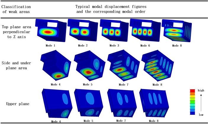
Fig. 4Weak areas of the whole lens hood
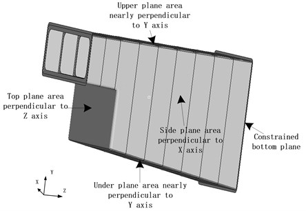
Fig. 5Reinforce solution with hat beam
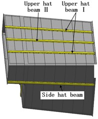
a)
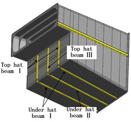
b)
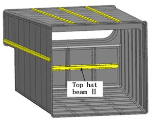
c)
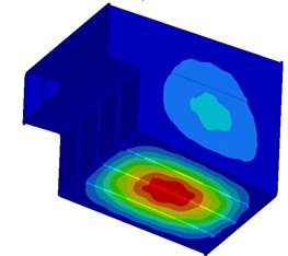
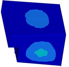
The constraint natural frequency of reinforced structure has a significant increase and it reaches up to 33.0 Hz, which is more than twice the original constraint natural frequency. Modal displacement of the reinforced structure is given in Fig. 7. The total mass of the reinforced structure is 50.4 kg.
Fig. 6Sectional dimensions of the hat beam
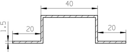
Fig. 7Modal displacement of reinforced structure
a)
b)
3.3. Placement of satellite subassemblies
Generally speaking, most traditional lens hoods only load some light antennas since they are usually too flexible to load heavy subassemblies. However, the reinforced structure has a considerable constraint natural frequency increase which means it is enough stiff, so the author decides to put some heavier satellite subassemblies as well as antennas on it.
Fig. 8Placement of satellite subassemblies
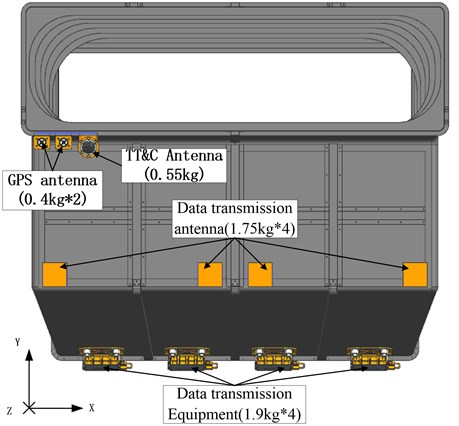
Subassemblies which are to be assembled on hood comprise GPS antenna, Telemetry, Track and Command (TT&C) antenna and data transmission devices (include data transmission antenna and data transmission equipment). Assembly of them can be considered as mass increase in assembly areas of the hood. According to the stiffness improvement methods, these subassemblies should be better assembled on areas which perform low modal displacement. Besides, considering that all kinds of antennas are sensitive to cover on their signal transmission paths, they should better be assembled on open areas. Based on such two principles, the final placement of satellite subassemblies is carried out and given in Fig. 8. With satellite subassemblies, the natural frequency of the lens hood is 31.4 Hz, and the total mass of lens hood and satellite subassemblies is 66.35 kg.
4. Optimization of reinforced structure
Lightweight is highly required for satellite assemblies, and the whole lens hood is required to be no more than 48.95 kg with satellite subassemblies. So, the author conducts an optimization which aims at further improving its natural frequency under the constraints of the hood’s weight and thickness of the shells [11]. The optimization can be described as:
• Objective function: Maximize: f=g (T1, T2, T3, …, T10),
• Constraints: M≤ 48.95kg (with satellite subassemblies),
• T1, T2, T3, …, T10 = 0.1*n (n is an integer and n≥ 8).
Where, T1-T10 stand for the thickness of beams and shells and the details are given in Table 1 (Top I stands for Top hat beam I, the same goes for the rest items). f is the constraint natural frequency of the whole lens hood (with satellite subassemblies) and it is determined by T1-T10 through function g, M is the total weight of lens hood. Due to the fabrication process of carbon fiber, the thickness of the shell can only be integer times of 0.1 mm and the shell thickness should be no less than 0.8 mm. Initial thicknesses are set to be 1.5 mm as the input of the optimization for all the shell types.
Table 1The corresponding shell types of T1-T10
Name | T1 | T2 | T3 | T4 | T5 | Name | T6 | T7 | T8 | T9 | T10 |
Shell type | Top I | Top Ⅱ | Top Ⅲ | Under I | Under Ⅱ | Shell type | Side | Upper I | Upper Ⅱ | Optical stop | Rest |
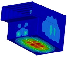
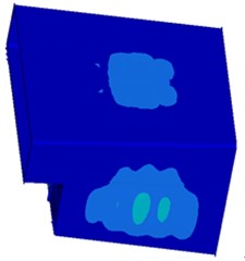
The optimization converged after 12 iterations. The optimized natural frequency is 36.5 Hz and lens hood weights 48.95 kg with satellite subassemblies. The iteration history is shown in Fig. 9 and the final results are given in Table 2. The modal displacement after optimization is given in Fig. 10. It is quite obvious that the ratio of frequency to mass performs a big progress after the optimization. (1.77 times as much as the reinforced structure).
Fig. 9Iteration history of the optimization
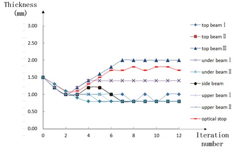
Table 2Initial size and optimized size of the lens hood
Item | Top beam Ⅰ | Top beam Ⅱ | Top beam Ⅲ | Under beam Ⅰ | Under beam Ⅱ | Side beam |
Initial size (mm) | 1.5 | 1.5 | 1.5 | 1.5 | 1.5 | 1.5 |
Optimized size (mm) | 1.0 | 0.8 | 2.0 | 1.4 | 0.8 | 0.8 |
Item | Upper beam Ⅰ | Upper beam Ⅱ | Optical stop | The rest | Lens hood mass | Natural frequency |
Initial size (mm) | 1.5 | 1.5 | 1.5 | 1.5 | 50.4 kg | 33.0 Hz |
Optimized size (mm) | 0.8 | 0.8 | 1.7 | 0.8 | 33.0 kg | 36.5 Hz |
Fig. 10Modal displacement of optimized structure
a)
b)
5. Sweep test of the lens hood
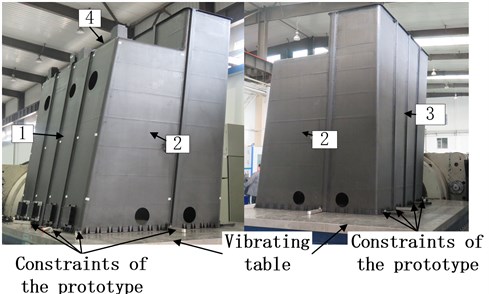
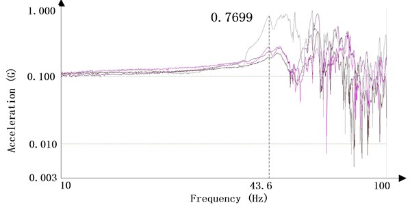
According to the optimized results, the lens hood prototype is fabricated and weights 49.45 kg with satellite subassemblies. To verify the constraint natural frequency of the fabricated lens hood, frequency sweeping experiments along x-axis (nearly perpendicular to side plane) and y-axis (nearly perpendicular to upper plane) of the lens hood are held respectively. The lens hood prototype and test ground are given in Fig. 11. Points 1-4 in Fig. 11 are chosen as the mounting points of acceleration sensors since the biggest modal displacements of each surface occur near the points in analysis. The bottom of the lens hood is constrained on the testing plane and all the satellite subassemblies are also firmly assembled on the hood. The sweeping results are given in Fig. 12 and Fig. 13.
Fig. 11Lens hood prototype and frequency sweeping testing ground along x-axis
From Fig. 12 and Fig. 13 it’s clear that the fist-order resonance frequency is 36.82 Hz along y-axis and 43.6 Hz along x-axis respectively. It can be easily concluded that direction of the first-order modal displacement is along y-axis. The testing result (36.82 Hz) is only a little higher than the analysis result (36.5 Hz) mentioned in Section 3, they match each other well.
Fig. 12Frequency sweeping result along y
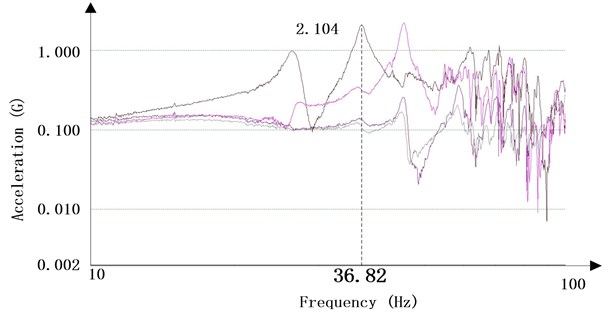
Fig. 13Frequency sweeping result along x
6. Conclusions
This paper has designed a lens hood with high stiffness and ability to load 15.95 kg satellite subassemblies. Initial structure is designed based on the external dimensions of the optical system. PST analysis shows its optical feasibility while FEM analysis shows its mechanical inadequacy. In response, a stiffness improvement methods is promoted to reinforce the initial structure. Subsequently, an optimization at key sizes is held to more improve the constraint frequency and decrease the weight. At last, a lens hood prototype is fabricated according to the design and frequency sweeping tests is held on it. The test results have confirmed the correctness of whole design and method. The work of this paper is meaningful to the shell and plate structure in which high stiffness is required.
References
-
Imai Hiroko, et al. Conceptual Design of Advanced Land Observing Satellite-3. SPIE Europe Remote Sensing, 2009.
-
Lei Wei, Lei Zhang, et al. Design and optimization for main support structure of a large area off-axis three-mirror space camera. Applied Optics. Vol. 56, 2017, p. 1094-1100.
-
Yang Shuai, et al. Integrated optimization design of carbon fiber composite framework for small lightweight space camera. Journal of the Optical Society of Korea. Vol. 20, Issue 3, 2016, p. 389-395.
-
Moldabekov M., Akhmedov D., Yelubayev S., et al. Features of design and development of the optical head of star tracker. SPIE Remote Sensing, Vol. 9241, 2014, p. 924122.
-
Yan P., et al. Stray light removing design and simulation of the three-mirror optical system used in field bias. Infrared and Laser Engineering, Vol. 40, Issue 10, 1997, p. 2002-2011, (in Chinese).
-
Chiang Z. S., Chang R. S., Hu C. H. Design of a new type of baffle for a space camera. ICIC Express Letters, Vol. 6, Issue 6, 2012, p. 1447-1452, (in Chinese).
-
Lin Z. W., et al. Application of carbon fiber reinforced composite to space optical structure. Optics and Precision Engineering, Vol. 15, Issue 8, 2007, p. 1181-1185, (in Chinese).
-
Bathe Klaus Jürgen Finite Element Procedures in Engineering Analysis. Prentice-Hall, 1982.
-
Hibbeler Russell C. Structural Analysis. 6th Edition, Prentice-Hall, 2005.
-
Hasselman Timothy, Chrostowski J., Ross T. Interval prediction in structural dynamic analysis. 33rd Structures, Structural Dynamics and Materials Conference, Structures, Structural Dynamics, and Materials and Co-located Conferences, 2013.
-
Liu Weixin Mechanical Optimization Design. Tsinghua University, Beijing, 1986.
-
Stute Thomas Recent developments of advanced structures for space optics at Astrium, Germany. Optical Materials and Structures Technologies, Vol. 17, Issue 5, 2003, p. 292-302.
-
Zhang Lei, et al. Research on lightweight outer baffle for coaxial space camera. International Conference on Electronic and Mechanical Engineering and Information Technology, 2011, p. 3263-3265, (in Chinese).
-
An Y., Yao J. Application of carbon fiber reinforced plastic for optical camera structure. International Conference on Mechatronics and Automation, 2012, p. 1928-1932.
-
Ding Fujian The FEA of outer baffle and dynamics optimum design of baffle. Acta Photonica Sinica, Vol. 28, Issue 1, 1999, p. 75-79, (in Chinese).
-
Yu Daoying, Tan Hengying Engineering Optics. China Machine Press, 2011, (in Chinese).
-
Li W., Guo Q. F. Application of carbon fiber composites to cosmonautic fields. Chinese Journal of Optics, Vol. 4, Issue 3, 2011, p. 201-212, (in Chinese).
-
Zhang Guoteng, et al. Testing research on mechanical properties of T700 carbon fiber/epoxy composites. Fiber Composites, 2009.
-
Geary Joseph M. Introduction to Lens Design. Willmann-Bell, 2002.
-
Guan Yingjun, Mu D., Li Z. Design and analysis of outer baffle of space telescope. The International Conference on Computational Intelligence and Industrial Application, 2010, p. 477-485.
-
Soo Kim Young, Lee E. S., Woo S. H. System trade-off study and opto-thermo analysis of a sunshield on the MSC of the KOMPSAT-2. Journal of Astronomy and Space Sciences, Vol. 20, Issue 2, 2003, p. 393-402.
-
Perrygo Charles M. Development of sunshield structures for large space telescopes. Proceedings of SPIE – The International Society for Optical Engineering, 2003, p. 220-209.
-
Luo J., Gea H. C. A systematic topology optimization approach for optimal stiffener design. Structural Optimization, Vol. 16, Issue 4, 1998, p. 280-288.
-
Lee Feinberg D., et al. Space telescope design considerations. Optical Engineering, Vol. 51, Issue 1, 2012, p. 1006.
About this article
Xiaoxue Gong developed the stiffness improvement theory and is the main designer of the lens hood. Lei Zhang checks Mr. Gong’s work and given some important advises on theory and structure design. Lei Wei assists Mr. Gong to complete the design and mainly completes the confirmatory tests. Xuezhi Jia is on duty of the manufacturing process of the lens hood. Ming Xuan checks all the work and gives some corrections on theory.

