Abstract
The proposed research work involves, solar photovoltaic array fed brushless DC motor drive using sensorless technique for reducing vibration with Enhanced DC-DC converter. The purpose of this research is to reduce the vibration in the motor drive and to improve the efficiency of the enhanced converter. The designed model consists of Buck and Boost converter, DC-link unit, state-of-the-art back-EMF sensing methods like terminal voltage, terminal current sensing and also includes third choral voltage amalgamation, back-emf integration and PWM strategies. In addition, reduced number of switches in the proposed research makes the scheme more outlay efficient and the motor speed is synchronized by PI controller. For sensing the vibration during rotation and shock in the brushless DC drive an accelerometer which is an electromechanical device are used, it measures acceleration forces associated to the freefall cause, path of the acceleration is a vector product. The current technique based on evaluation of various parameters are clearly modeled and experimented. A MATLAB platform and a hardware prototype of multioutput buck-boost converter are clearly examined for various effective environment in the proposed research.
Highlights
- To design an enhanced buck-boost converter for increasing the lifetime of the ampere-hour unit in discontinuous condition.
- To design a multi output enhanced BB converter for B4-inverter.
- To increase the performance of enhanced BB converter.
- To design enhanced BB converter involving lesser components for reducing the current conduction losses.
- To regulate the load voltage highly in all the power flow situations by employing three-domain load voltage control method.
1. Introduction
There has been a great increase in energy utilization recently as a result and environmental issues like pollution are seen globally leaving a path for energy conservation technologies renewable energy sources and pollution, free electrical machines in addition to efficient energy transmission devices are needed to resolve energy consumption issues. Brushless direct current motor (BLDC) is utilized to enhance the efficiency to torque production because it has no brush. It also has features like removing ionizing sparks from commutator increment in power and overall lower electromagnetic interference (EMI) it is also high in speed and torque characteristics, effectiveness, dependability, long existence and soundless performance. It is able to convert electricity into mechanical power better than brushed DC motors due to absence of electrical and friction losses. It is also easier to handle than AC motors [1]. In brushed the presence of brushes, control load and torque are hyphenated current ratios to DC and AC motors are high. One of the smart applications for solar Energy conversion technique is solar water pumping. The overhead of solar energy equipment and water pump may diminish in the upcoming days and so the elements for PV power will increase. Hence PV water pumping system will be more economical option in the future [2]. Solar energy water pumping systems are commonly used to meet energy demand for household activities in addition to the other day-to-day requirement. Pumps are known for low maintenance ease of installation, reliability the capacity to balance between PV power and usage of water. With the emerging advancements in technology, BLDC has a major role in automotive applications, mainly on Electric Vehicles (EV) and fuel pumps as it is highly efficient, of compact size and of low maintenance than the brushed DC motors [3]. The motors position information must be known for current commutation in order to achieve accorded and harmonic-free instant torque of BLDC. This can be done by using hall sensors on motors [4]. EVs are utilized for transportation applications to achieve environmentally friendly operation with the help of buttery. Future electric vehicles (230 W, 23.9 V), Xingwei (400 W, 49 V) and Taizhou Quanshun Motors Co., Ltd (900 W, 49 V) are some examples of brushless DC hub motor based EV and used now more over voltage levels are dissimilar in PV energy and energy storage systems (ESS) like ampere-hour unit. This creates a need for a DC-DC converter that can maintain appropriate power flow among input source, there would be an increase in cost, mass and losses. So multi-input DC-DC converters are used widely in hybrid power systems [5]. With the use of transformer faces losses in its core and windings [6]. This paves the way for those of non-isolated multi-input DC-DC converters in electric vehicles. Z-Source Inverter (ZSI) based solar energy water pumping system is proposed by ZSI. It consists of solar energy array, ZSI, BLDC coupled with a centrifugal and a control system unit. An experiment [7] is conducted on the configuration of solar energy array utilized with BB converter fed BLDC drive coupled with a water pump. The power generated from solar energy array is considered during partial shading. Hence backup powered system is needed in BB which is absent in solar energy BLDC water pumps. Likewise, the number of power utility devices is higher in BB which leads to power losses and its efficiency.
2. Materials and methods
Though solar energy has been emerging as the most widely used renewable energy, various ecological situations like temperature and solar variation make their characteristics curve inconsistent in MPPT. This is a big challenge in the tracking of solar power, mainly at partial shading the portion or whole set of the solar energy is of a uniform isolation [8]. The unexpected alter in solar variation result in the lessening of estimated sun energy. Hence the ampere-hour unit feedback powered system is considered for meeting an efficient converter is required. To achieve this, six switch inverters is reconfigured to four-switch three-phase inverter (B4-inverter). So, reduction in the switch/leg failure, cost and system size are obtained [9-13].
2.1. Objectives of the proposed research and advantages of Buck-Boost converter
The main objectives of the present research are as follows:
1) To design an enhanced buck-boost converter for increasing the lifetime of the ampere-hour unit in discontinuous condition.
2) To design a multi output enhanced BB converter for B4-inverter.
3) To increase the performance of enhanced BB converter.
4) To design enhanced BB converter involving lesser components for reducing the current conduction losses.
5) To regulate the load voltage highly in all the power flow situations by employing three-domain load voltage control method.
6) To check the performance of the enhanced BB converter for commercial applications.
Advantages of Buck-Boost converter:
– DC-DC converter is improved by topological modifications.
– Power budgeting between input energy source and load can be integrated by controlling the power supplied by input DC source.
– An inherent and voltage and power flow control achieved by operating the three-port converter (TPC) (solar power, ampere-hour unit, Multi output BB converter) in unidirectional way.
– Speed control of BLDC motor is achieved without steady state error with satisfactory closed loop.
– The performance of TPC with three different domains (AHEU, AHDU and SEU) is improved with less losses and a smaller number of components.
An accelerometer is an electromechanical device. It senses acceleration forces connected to the freefall cause. There are some accelerometers that are used to view the magnitude and direction of the acceleration as a vector to sense position, vibration and shock. One of the commonly used accelerometers is made of a Newton’s law of mass acceleration and Hooke’s law of spring action. In its acceleration is experienced both the mass and the casing equally. Acceleration is observed due to the displacement. The initial position of the rotor winding is determined by the stator winding of the BLDC motor with non-linear magnetic dispersion characteristic. To avoid this, rotor position detecting and speed up methods including short pulse and long pulse sensing can be approved based on the saturation effect of the stator iron. Short pulse sensing employs a voltage pulse train made of the successive short while long pulses generate position torque to speed up the motor. This does not cause any reverse rotation and vibration during start up process. Further, the rotor position can be identified based on the response speed of the stator current and the response peak value of the current of the stators.
Fig. 1Experimental test setup of BLDC motor controller using accelerometer for vibration measurement
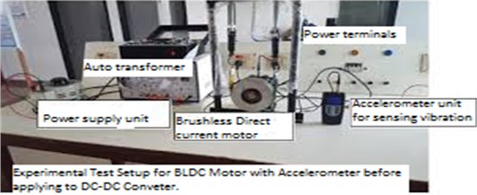
The stator winding of the BLDC motor has non-linear magnetic dispersion characteristic, which is the basis for decisive for the initial position of the rotor winding. To overcome these disadvantages, the rotor position detecting and speed up methods based on saturation effect of the stator iron can be applied, such as the short pulse sensing technique. This technique adopts a voltage pulse train composed of the successive short and long pulses to generate positive torque to speed up the motor, and it does not bring any reverse rotation and vibration during the start-up process of BLDC motor so accelerometer is used for sensing vibration at rotation, it is carried on the experimental and it is shown in Figure.1. The response speed of the stator current and the response peak value of the current of the stator winding can be used to detect the rotor position.
2.2. Design of standalone multioutput Buck-Boost converter fed B6-inverter and two-stage solar array ampere-hour unit powered motor system
A multi-output BB power-controlled device is designed based on B6-inverter fed BLDC drive system. This system comprises modified voltage balancing unidirectional BB converter for tracking the highest power from solar energy panel, ampere-hour unit powered bidirectional BB converter that acts as backup supply for BLDC operating under demand condition in addition to B6-inverter fed BLDC. The MPPT is tracked iteratively by increasing or decreasing the output voltage at the MPPT of the solar energy unit with the employment of basic Perturb and Observe (P&O) method. Further, its implementation is quite simple. Meet the energy demand, an ampere-hour unit as an energy storage device and a bidirectional DC-DC converter utilized during partial shading condition. A standalone consistent solar energy ampere-hour unit powered backup system can be applied for different purposes when solar power produced is beyond the energy needed by the load a rechargeable ampere-hour unit can be used for saving the energy. This energy could be utilized for sustained operation of the system during the shad of the solar energy panel.
2.3. Design standalone multioutput Buck-Boost converter fed B4-inverter and single-stage solar energy ampere-hour unit powered BLDC drive
In the switching state, when power controlled device (S1) is energized, the diode (D2) becomes forward biased, so switch (S2) is energized/de-energized, similar circuit of proposed converter is represented in Fig. 2, during switching, input DC source (Vin) charges the inductor (L1), hence the inductor current increases, during this process, intermediate capacitor (C1) and input DC source (Vin) de-energizes the energy to the output capacitor(C02) through diode (D2). Further, capacitors (C01 and C02) get de-energized to the motor as shown in Fig. 2. In enabling state 1, Mosfet (S2) is energised controlled device (D1, D2) are reverse biased and the Mosfet (S1) is turned off. During this inductor (L1) current energizes the capacitor (C1). When the inductor current gets reduced the capacitor (C1) currents gets increased. In this mode, capacitors (C01, C02) get de-energized and they supply the energy stored to the load resistances (R1, R2). The inductor and capacitors, current and the voltage Eq. (1) are given below:
Fig. 2Modes of operation
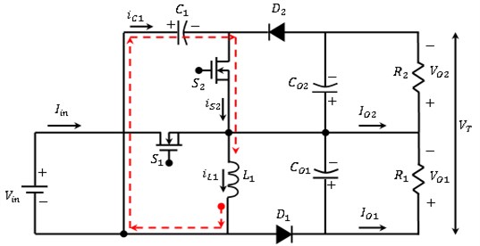
a) At Enabling position 1, the Mosfet (S2) is energized, diodes (D1, D2) are reverse biased, the Mosfet (S1) is denergised. Meanwhile, an inductor (L1) current charges the capacitor (C1), inductor current discharges and capacitor (C1) current increases. At this mode capacitors (C01, C02) get discharges, delivers the energy to load resistances (R1, R2)
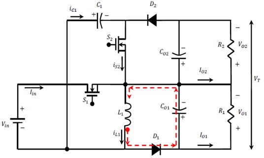
b) At Enabling position 2, both the Mosfets (S1, S2) are de-energized. diode (D1) is forward biased. Henceforth inductor (L1) current boost the capacitor (C01), hence the inductor current goes down and capacitor (C01) current increases. Output capacitors (C01, C02) get discharged and delivers the energy to load resistances (R1, R2)
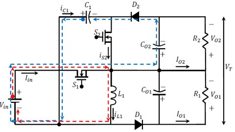
c) At Enabling position 3, Mosfet (S1) is energized, diode (D1) gets forward biased so Mosfet (S2) is energized/de-energized. DC supply (Vin) boost the inductor (L1), meanwhile the inductor current boosted. Henceforth, in-between capacitor (C1) and DC supply (Vin) delivers/discharges its energy to the output capacitor (C02) via diode (D2) and capacitors (C01, C02) gets de-boosted and supply their energy to corresponding load resistances (R1, R2)
2.3.1. Scheme of operation of enhanced system and losses on power-controlled device S1,2during conduction
The contribution of current research depends on the MOBB converter by selecting a Proportional Integral (PI) controller for a closed loop control Scheme. The PI controller attempts to identify the error on the measured process variables and the desired set point through calculation and then provides a desired output, ultimately it controls the process. The PI controller computation has two unique modes: proportional mode and integral mode. In the proportional mode, the current error is decided, but in the integral mode, the reaction-based recent error is detected. The two modes provide the output accurate action to the control element. PI controller is used in industries due to its simple design and unrefined arrangement. PI controller algorithm can be run by Eq. (2):
where err(t)= set voltage – actual voltage.
Fig. 3Control of MOBB converter
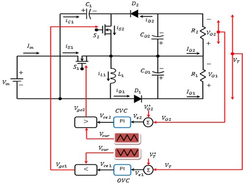
From figure 3 the Control of MOBB converter, and output voltage control (OVC) compare the output voltage (V*out) of or MOBB converter with actual output voltage (Vout) for creating error voltage (Vce1), provided in Eqs (3), (4). Hence error generator of capacitor voltage control (CVC) compare MOBB converter capacitor (C01) voltage (V*01) using output voltage (V01) and generates an error voltage (Vce2):
2.3.2. Losses on power-controlled device S1,2 during conduction
Power controlled device S1,2 during conduction losses are evaluated, an accurate voltage drop which is series with linear resistor (RDSon = 0.07) are estimated. RDSon depends on the input gate to source voltage VGS and the junction temperature. The losses on power-controlled device S1,2 during conduction S1,2 are given in Eq. (5):
where () represents the current curving during the power-controlled device (), () gives the “ON” time of power-controlled device (). Switching ampere determined as () is derived from Eq. (6):
Harmonics current () are given as in Eq. (7):
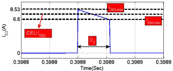
where () and () gives high and low magnitude of power-controlled device () current as illustrated in Fig. 4. From Fig. 4, 0.22, 7.565 and 0.965, which are substituted in Eq. (8), sum amperes and losses are derived from Mosfe () as resolved in Eq. (8):
Fig. 4Mosfet (S1,2) conduction waveform at openloop condition
2.3.3. Energizing and de-energizing losses of power-controlled device () during starting
Electrical parameters of power-controlled device are given as IRFZ24N ( 34ns, 27 ns, 34 V) for getting accurate MATLAB simulation and theoretical calculations. The power-controlled device () swapping on and off losses of power controlled device () during starting condition () is illustrated in Eq. (9):
where current across the conduction of two Mosfet switch ‘1,2’ are obtained in Eq. (8), is of power controlled device () and functional switching frequency used for switch is 5 and 10 kilo-(). Total loss is predicted from Eq. (10):
2.3.4. MOBB converter diode () losses
MOBB converter diode () losses due to forward voltage ( 0.8) is expressed by Eq. (11):
where () is ampere via diode, (), () represents “ON” time of diode (), () stands diode (), at initial current and () represents sum harmonics amps of diode (). The diode current at initial () is zero, hence the harmonic amps () is obtained from Eq. (12):
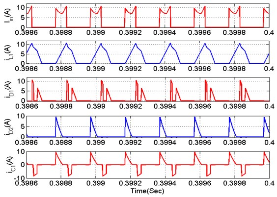
where (), () represents the high and low magnitude of diode (), which is shown in Fig. 6. Fig. 6 shows 0.15, 0 and 3.25. Thevalues are substituted in Eq. (13), the total current conduction and the power loss of diode (), as resolved in Eq. (13):
2.3.5. MOBB converter inductor losses ()
The open loop waveforms of inductor () of MOBB converter are shown in Fig. 5. Meanwhile, inductor losses () have two factors. First factor wire loss, core loss. It is given by Eq. (14) due to wire:
where () indicates for the current flow through the inductor (), () gives the “ON” period of inductor (), () shows inductor () current at time of triggering, ( 0.9) stands for the equivalent DC resistance of 0.1 mH Ferrite core inductor and () indicates to the sum harmonics amps of inductor (). The inductor current at the instant of starting () equals to zero, therefore the mean harmonic current () is given in Eq. (15):
Fig. 5Asymmetrical output voltage control of MOBB converter

a)
b)
Estimating the asymmetrical performance of MOBB converter, input voltage as ( 18 V) as shown in Fig. 6(a). Output voltages of the MOBB converter are regulated on ( 24 V and 24 V). Henceforth, the sum output voltage and sum power are regulated on total voltage ( 48 V) and ( 40 W). Moreover, load resistances ( 28.8) are considered for symmetrical condition. Where (), () represent the maximum and minimum amplitude of inductor ( current as illustrated in Fig. 6. It illustrates clearly that 0.67, 0 and 5.25. These values are substituted in Eq. (16), the total current conduction and power loss of inductor ( are resolved in Eq. (16):
Fig. 6(a-h) Estimation of power losses. (i) Asymmetrical output of MOBB converter

a)

b)

c)

d)

e)

f)

g)

h)

i)
2.3.6. Calculation losses in MOBB converter
Losses of MOBB converter is the average of all the aspects detail mentioned in Eqs. (1-16). The sum power losses () and system efficiency can be calculated making use of Eq. (17):
Output power of MOBB converter (40 W) and refers to power losses.
The multioutput BB converter-fed B4-inverter and single-stage solar energy-ampere-hour unit powered motor load is shown in Fig. 7.
Fig. 7Proposed Single-Stage standalone PV battery powered BLDC drive
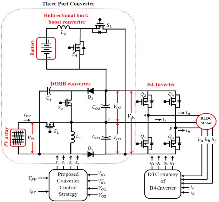
It is seen from Fig. 7 PV solar energy ampere-hour unit powered BLDC that the boosted-up voltage is obtained with control driven speed is obtained. The proposed research includes multioutput Buck-Boost converter for MPPT and ampere-hour unit current regulation correspondingly, and B4-Inverter cum motor system which is embarrassed by an electronic commutation. So electronic commutation fed on rotor position is utilized than mechanical commutation to restrict tear, sparking and wear of brushes and commutator assembly. Correspondingly, the speed of the BLDC is directly proportional to the applied inverter input voltage; hence, the speed control is created by the variable input voltage of B4-Inverter. As a result, it allows the fundamental frequency switching of B4-Inverter and gives reduced switching losses.
The electronic commutation of the BLDC includes the accurate switching of B6/B4-Inverter in such a way that a symmetrical DC current is fed from the DC link capacitor for 120 and placed symmetrically at the center of each phase. The B4-Inverter and the B6-Inverter are briefly compared, and the results are tabulated in Table 1. This system is efficiently utilized in the applications of solar energy water pumps, solar powered motor drives, solar electric vehicles (EV), EV charging stations and solar fuel pumps.
Table 1Comparison of conduction of power-controlled devices B6 and B4
Sector | Conduction of power-controlled devices for B6-inverter | Conduction of power-controlled devices for B4-inverter |
0-60 | , | , |
60-120 | , | |
120-180 | , | |
180-240 | , | |
240-300 | , | |
300-360 | , | , |
Sum of power-controlled devices conduct at (0-360) | 12 | 8 |
Switching losses (for 310 W system) | 2.52 Watt | 1.46 Watt |
2.4. Estimation analysis of solar energy powered MOBB converter and ampere-hour unit powered bidirectional converter
Based on the connection between solar energy generation power and load demand power, proposed structure work in diverse power flow modes such as ampere-hour energizing unit (AHEU), solar energy unit (SEU) and ampere-hour de-energizing unit (AHDU). The working modes in these three domains are analysed below in detail.
2.4.1. Ampere-hour energizing unit (AHEU)
In this approach, solar energy supplies power to load and also delivers power to ampere-hour unit. This situation occurs when solar power is more than the load power, therefore ampere-hour unit must to be charged. In AHEU, power-controlled devices (, , ) are energized and power-controlled device () is entirely de-energized in AHEU which are indicated as red, blue, green colour dotted lines as shown in Fig. 8.
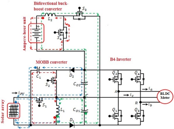
Fig. 8. Schematic circuit of MOBB converter works in AHEU
2.4.2. Solar energy unit (SEU)
With this approach, solar energy only supplies to loads. This situation happens when solar energy power is equal to motor power. During SEU, power-controlled devices (, ) are energetic and power-controlled devices ( and ) are de-energised. The diverse operation in SEU are indicated in red, blue, green colour dotted lines as shown in Fig. 9.
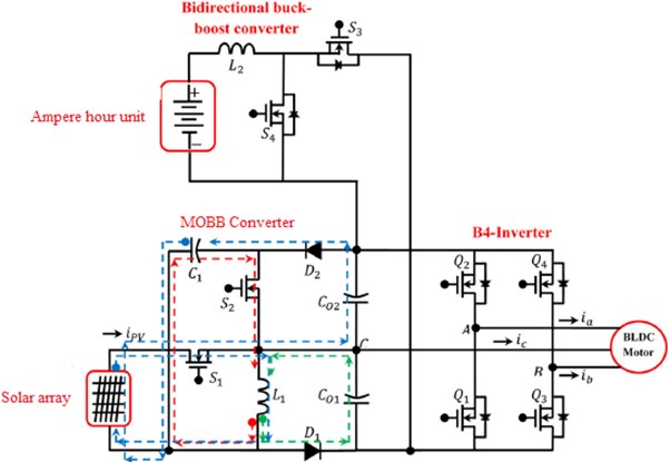
Fig. 9. Schematic circuit of MOBB converter works in SEU
2.4.3. Ampere-hour de-energizing unit (AHDU)
In this approach, two sources of solar energy and ampere-hour unit are in charge for delivering power to the load. In AHDU, power-controlled device (S3) is de-energized and power controlled device (, , ) are in operating conditions they are indicated in red, blue, green colour dotted as shown in Fig. 10 in AHDU.
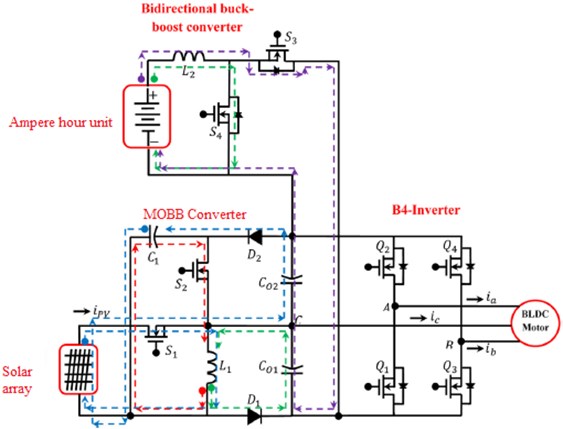
Fig. 10. Schematic circuit of MOBB converter works in AHDU
In this approach, power-controlled switches 1,2,3,4 are de-energized. At the same time remaining current stored in inductor 2 starts discharging to output capacitor 1,2 through power-controlled body diode 3. Meanwhile the diode 1 is forward biased to generate circulating current path of inductor 1and current across inductor 1 gets reduced. The corresponding circuit of projected converter works in this approach, are illustrated in “purple dotted” as shown in Fig. 10. The torque ripple occurs synchronously with the BLDC motor at rotary motion and also the recurring controller consists large loop gain (basically infinity) only for the fundamental recurring frequency component and its harmonics. Due to these conditions, the recurring control system is effective to reduce the vibration due to periodical torque ripples. However, the vibration signals detected by the acceleration sensor contain different frequency components and the mechanical system around the motor and load has convoluted resonant characteristics, we cannot stabilize the recurring control system and reduce the vibration by directly using the vibration signals from sensorless [8]. Then, we examine the approach which only one frequency component of the vibration signal is extracted from the vibration signals detected by the acceleration sensor, and the recurring control is performed for every frequency component of the vibration during three domain conditions AHDU, AHEU, SEU.
Nomenclature. Switches , , , are indicates as switches ‘1’, ‘2’, ‘3’, ‘4’. Capacitors , are indicated as capacitors ‘1’, ‘2’. Inductor are indicated as inductors ‘1’. Diodes , are indicated as diode ‘1’, ‘2’.
2.5. Control scheme of MOBB converter
The control Scheme is proposed [14] is to obtain constant voltage and control current storage capability of the topology to improve the energetic rotating response of the converter when load or input voltage fluctuations are applied.
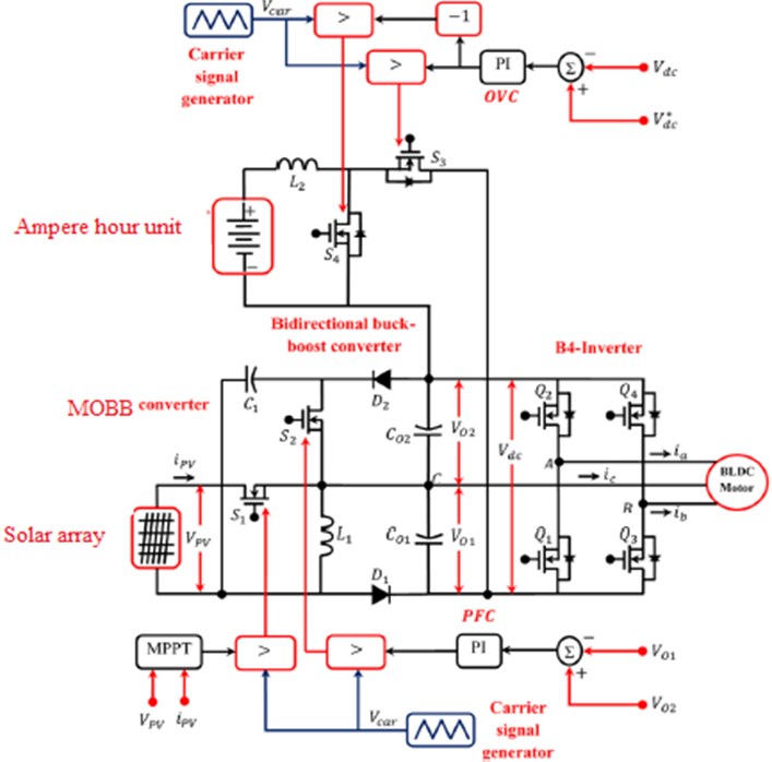
Fig. 11. Feedback control scheme of MOBB System
The MOBB converter can raise/diminish the voltage to a low-level voltage input power to a convenient voltage DC bus and mid-level voltage load terminals. The Enhanced MOBB converter has two outputs with similar/dissimilar voltage levels which makes adaptable for interfacing B4-Inverter employed BLDC motor drive. B4-Inverter which is used is a non-floating DC-links. After comparing all the signals, error produced is processed through output voltage controller (OVC) and then processed signal is fed to PWM generator as shown in Fig. 11.
2.6. DTC of B4-inverter fed BLDC motor drive
Figure 12 shows the drive with dual phases (phase-A and phase-B) of the BLDC motor supplied from the B4-Inverter legs, while the other one (phase-C) is linked to the middle point of the DC-bus voltage. Assume the four dynamic voltage vectors generated by the B4-inverter under the two-phase operation modes. The corresponding switch groupings (, , , ) are equal to (1000), (0010), (0100), and (0001), where, from left to right, the binary values denote the state of the upper and lower switching signals, corresponding to phase-A and phase-B, respectively therefore three-phase conduction mode illustrated as (, , , ).
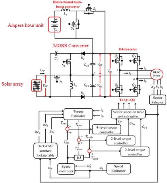
Fig. 12. DTC scheme of B4-inverter
The DTC armature of B4-inverter is shown in Fig. 10. Note, that the functioning scheme does not contain a flux loop, and that the detection of the sectors in the (-) plane is achieved considering suitable combinations of Hall sensor signals, as in Table 2.
Table 2Sector identification basis on hall signals
(100) | (011) | (010) | (101) | (100) | (110) | |
Sector | I | II | III | IV | V | VI |
The velocity remains stable during a specified sector with an opening of and is equal to the standard one in the previous sector. The ensuing algorithm is expressed as following Eq. (18):
where () is the pole pair number of the BLDC motor and () which is the time period exhausted to cross the previous sector. The inference of the electromagnetic torque is based on [15], which is expressed as subsequent Eq. (19):
where (, and ) are feedback normalized functions, attained by interpolation and gives in lookup table. The electromagnetic torque reference is expressed as the subsequent Eq. (20):
The vector selection table can be incorporated by taking into account both anticlockwise and clockwise rotations of the BLDC motor, as given in Table 2.
Fig. 13Six sectors restricted by the 4 vectors yielded by the 2-phase conduction mode and the larger ones harvested by the 3 phase conduction mode
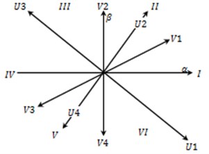
Table 3Vector selection table of a DTC strategy
+1 | –1 | |
Sector I | (0001) | (0001) |
Sector II | (0101) | (1001) |
Sector III | (0110) | (1000) |
Sector IV | (1000) | (0010) |
Sector V | (1010) | (0110) |
Sector VI | (1100) | (0100) |
Referring to Table 3, we understood from sector I to VI motor have torque conflicting to the phase-A and phase-B. Correspondingly, the currents are momentarily twisted by adverse surges in order to generate required torque. Using, control torques () and () by phase-A and phase-B, respectively, required torque of motor () is produced. Substituting in table such as the yields of the two-level controllers of () and () are obtained by using the Table 4 () and () correspondingly.
Table 4Vector table of BLDC drive sector 2 and 5
+1 | –1 | |||
+1 | –1 | +1 | –1 | |
Sector II | (0110) | (0101) | (1010) | (1001) |
Sector V | (1001) | (1010) | (0101) | (0110) |
3. Results and discussions
3.1. Implementation of single stage standalone supply system for BLDC drive
Implementation of the MOBB converter, simulations are carried out for ideal, ampere-hour unit de-energizing and energizing using MATLAB software. The simulation parameters of the MOBB system are listed in Table 5. Input voltage are 18 V, 23.9 V. The output voltages regulated on (23.9 V) and (23.9 V). Correspondingly, sum output voltage required is regulated such as 48 V. Various parameters are measured for validating the proposed idea as indicated in Fig. 15.
Table 5Specifications MOBB system
S. No | Objects | Values |
75 W solar energy unit specifications at solar radiation of 1000 W/m2 | ||
1 | Solar energy voltage without load | 21.60 V |
2 | Solar energy current | 4.36 A |
3 | Peak solar energy unit voltage | 17.9 V |
4 | Peak solar energy unit current | 4.16 A |
5 | Peak solar energy unit power | 75 W |
6 | Solar Cell (Monocrystallin) | 156×156 |
7 | Number of cells (PCS) | 2×9 |
BLDC motor estimations | ||
8 | Estimated power | 40 W |
9 | Estimated torque | 0.124 Nm |
10 | Estimated speed | 3000 Rpm |
11 | Estimated DC link voltage | 23.9 V |
Ampere-hour unit specifications | ||
12 | Ampere-hour unit voltage | 24.1 V |
13 | Ampere-hour unit current | 7.0 Ah |
14 | Ampere-hour unit power | 167.0 W/h |
The characteristics of a 75 W solar energy can be replicated using MATLAB tool based on corresponding circuit model. Also it is obvious from Fig. 12; error point indicated peak power of each curve, as solar irradiation increases maximum power shifted upwards.
Fig. 14Solar energy
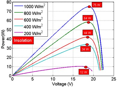
a) Power-voltage characteristics
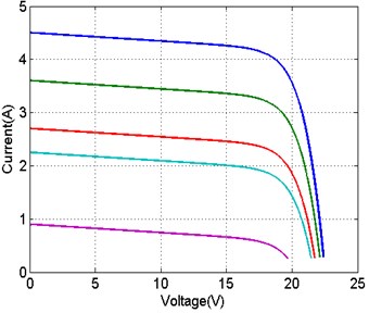
b) Current-voltage characteristics
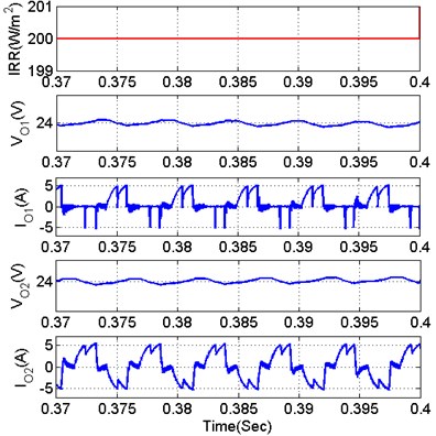
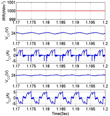
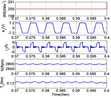
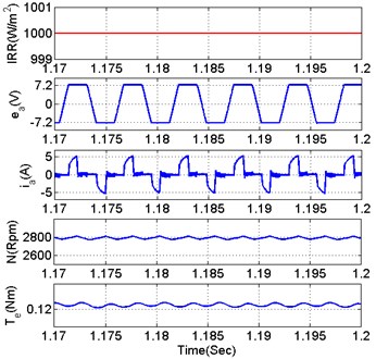
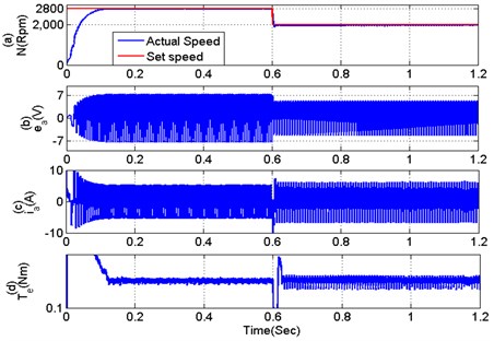
The new MOBB converter fed on B4-Inverter based motor system is evaluated in a MATLAB/Simulink environment using the sim power-system Toolbox. The Parameters as shown in Fig. 15 are validated. The sudden change in torque, the ripple is reduced so vibration in motor is reduced using accelerometer and MOBB converter, output voltage is shown in Fig. 8 when compared to conventional single output; dynamic performance validation of MOBB system under speed control are shown in Fig. 16.
Fig. 15Performance evaluation of enhanced method with different solar radiation condition
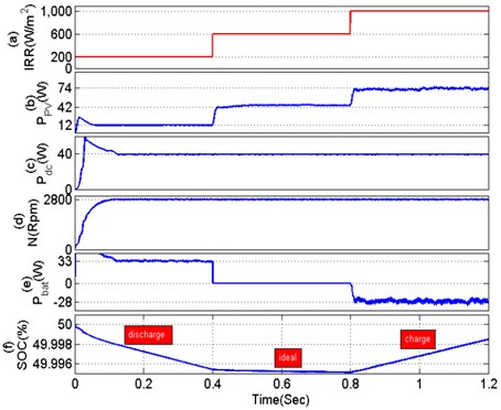
Fig. 16Dynamic performance evaluation of MOBB system at speed control
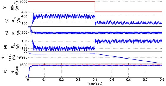
Fig. 17TPC parameters at different solar radiation: a) 200 W/m2, b) 1000 W/m2
a)
b)
Fig. 18BLDC motor parameters at different solar radiation: a) 200 W/m2, b) 1000 W/m2
a)
b)
Fig. 19Dynamic performance validation of MOBB system under speed and torque control with existing

a)

b)

c)

d)

e)

f)

g)

h)
i)
From Fig. 19 0.4 sec, a step change is generated on solar irradiation from 1000 W/m2 to 400 W/m2 as shown in Fig. 19(a). Due to change in environmental condition panel power is reduced from 450 W to 130 W respectively as shown in Fig. 19(b). The BLDC of power rating 40 W (estimated speed = 3000 Rpm, estimated DC link voltage = 23.9 V, estimated torque = 1.25 Nm and number of poles = 8) is taken as load port for proposed research. The estimated power of BLDC (load power) is 40 W and rotor speed is maintained at 2799 RPM as shown in Fig. 8(c) and 8(f) respectively. The required load power of 20 W at low irradiation case (600 W/m2) is efficiently extracted from the ampere-hour unit. Similarly, the surplus power of solar module (40 W) at maximum irradiation case (1000 W/m2) is efficiently stored in the storage ampere-hour unit according to the command power of ampere-hour unit management unit shown in Fig. 19(d). As seen from the Fig. 19(d), the negative sign gives that the ampere-hour unit gets the energy from the panel; meanwhile positive sign of ampere-hour unit provides energy to the load. SOC indicated in Fig. 19(e). The hardware component selection is shown in Table 6.
Fig. 20Performance of proposed MOBB involved B4-Inverter based BLDC motor under dynamics of solar irradiation and losses, switching frequency, conduction loss, duty cycle chart

a)

b)

c)
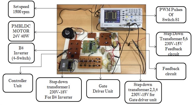
The system developed using the proposed method before has been tested in the laboratory is shown in Fig. 26. The overall system is controlled by a dsPIC30F4011 Digital Signal controller. The driver circuits are most widely used for driving the power-controlled devices like Metal-Oxide-Semiconductor Field-Effect Transistor (MOSFET) and Insulated-Gate Bipolar Transistor (IGBT). Power IGBTs and MOSFETs are voltage driven because their insulated gates behave like a capacitor.
Fig. 21Experimental and simulation output of V01C01
a)

b)
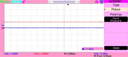
Input voltage applied to the MOBB, the voltage (230 V) is bow out to (15 V), changed to DC using bridge converter and input is fed to dsPIC microcontroller using voltage control device. Output of the microcontroller is displayed in the DSO. Fig. 21 gives the yield of capacitor voltage .
Fig. 22Experimental and simulation output of V02C02
a)

b)
Table 6MOBB converter B4-Inverter fed BLDC motor driver components specification
S. No | Objects | Values |
1 | Peak voltage of solar energy unit | 18.1 V |
2 | Peak current of solar energy unit | 4.40 A |
3 | Peak power of solar energy unit | 75 W |
4 | TPC output voltage | 48 V |
5 | TPC output power | 40 W |
6 | Approximate BLDC motor power | 40 W |
7 | Approximate voltage-current value of ampere-hour unit | 84 W/h |
When the input is applied to the MOBB circuit, the voltage (230 V) is bow out to (15 V), transformed to DC with the use of bridge rectifier and the input is given to the dsPIC microcontroller with the help of voltage control device. The output of the microcontroller is displayed using the DSO. Fig. 22 gives the yield of capacitor voltage .
3.1.1. Experimental output voltage waveform of the MOBB converter
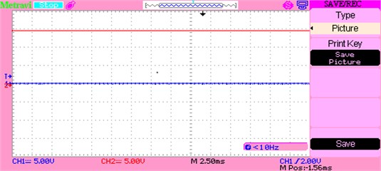
The Fig. 23 denotes the performance of the converter during boost mode to produce a voltage output of about 48 V. The 48 V generally appears as 24 V for each capacitor. The variation in voltage level also appears to be the same across the two capacitors.
Fig. 23Experimental and simulation total output voltage waveform during boost mode of MOBB
a)

b)
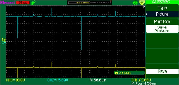
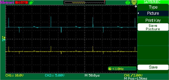
Fig. 24Experimental and simulation total output voltage during buck mode of MOBB
a)

b)
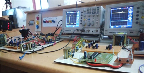
Fig. 25Prototype test setup of BLDC drive with different speeds and two output voltage balancing
The Fig. 24 denotes the validation of the converter during buck mode to produce a voltage output of about 24 V. The 24 V generally appears to be as 24 V and another 24 V across each capacitor. The variation in voltage level DC-link appears across the two capacitors.
In driver unit, a BC547 NPN type transistor is used to amplify the current at collector and emitter terminals, i.e., a small current at its base controls a larger current at collector and emitter terminals. The optocoupler (6N135) provides electrical insulation between the input and the output of converter. The basic design of an optocoupler consists of a light emitting diode (LED) that produces infra-red light and a semiconductor photo-sensitive device that is used to detect the emitted infra-red beam. The optocoupler (6N135) output is given as input to the driver integrated circuit (driver IC: 7667) for converting transistor-transistor logic (TTL) level signals into high current outputs at voltages up to 15 V. The IC7667 is a multioutput monolithic high-speed driver. Its high speed and current output enable it to drive large capacity of loads with high slew rates and low propagation delays.
Fig. 26Prototype test setup for single stage standalone supply system for BLDC drive
4. Conclusions
The current research has proposed an enhanced multioutput BB converter based on B4-Inverter fed BLDC drive system which is examined through MATLAB Simulation and its experimental setup is also carried out successfully. The multioutput BB converter based solar cell ampere-hour unit standalone system is ostensible compared to the existing individual multioutput systems. It includes the minimization of power losses, switching failures in the inverter and replacement of B6-inverter with B4-inverter. The vibration and shock are sensed in the brushless DC motor drive by accelerometer an electromechanical device and the components efficiency, losses of the proposed circuit are accurately analyzed. A MATLAB platform and hardware model of multioutput output Buck-Boost converter is developed for various effective environments used for industrial and agricultural applications.
References
-
Kh Mozaffari Niapour S. A., Danyali S., Sharifian M. B. B., Feyzi M. R. BLDC drives supplied by PV power system based on Z-source inverter and FL-IC MPPT controller. Energy Conversion and Management, Vol. 52, Issues 8-9, 2011, p. 3043-3059.
-
Ghoneim A. A. Design optimization of PV powered water pumping systems. Energy Conversion Management, Vol. 47, Issues 11-12, 2006, p. 1449-1463.
-
Gao J., Hu Y. Direct self-control for BLDC drives based on three-dimensional coordinate system. IEEE Transactions on Industrial Electronics, Vol. 57, Issue 8, 2010, p. 2836-2844.
-
Fang J., Zhou X., Liu G. Precise accelerated torque control for small inductance BLDC. IEEE Transactions on Power Electronics, Vol. 28, Issue 3, 2013, p. 1400-1412.
-
Tao H., Duarte J., Hendrix M. Three-port triple-half-bridge bidirectional converter with zero-voltage switching. IEEE Transactions on Power Electronics, Vol. 23, Issue 2, 2008, p. 782-792.
-
Mozafari Niapoor S. A. K., Danyali S., Sharifian M. B. B. PV power system based MPPT Z-source inverter to supply a sensorless BLDC motor. 1st Power Electronic and Drive Systems and Technologies Conference, 2010.
-
Rajan Kumar, Bhim Singh, Ambrish Chandra, Kamal Al Haddad Solar PV array fed water pumping using BLDC drive with boost-buck converter. IEEE Energy Conversion Congress and Exposition, 2015.
-
Kashif Ishaque, Zainal Salam A deterministic particle swarm optimization maximum power point tracker for PV system under partial shading condition. IEEE Transactions on Industrial Electronics, Vol. 60, Issue 8, 2013, p. 3195-3206.
-
Hoang K. D., Zhu Z. Q., Foster M. P. Influence and compensation of inverter voltage drop in direct torque-controlled four-switch three-phase PM brushless AC drives. IEEE Transactions on Power Electronics, Vol. 26, Issue 8, 2011, p. 2343-2357.
-
Onar O. C., Khaligh A. A novel integrated magnetic structure based DC/DC converter for hybrid battery/ultra capacitor energy storage systems. IEEE Transactions on Smart Grid, Vol. 3, Issue 1, 2012, p. 296-308.
-
Dehghan S. M., Mohamadian M., Yazdian A., Ashrafzadeh F. Multioutput input multioutput-output Z-source inverter. IEEE Transactions on Power Electronics, Vol. 25, Issue 2, 2010, p. 360-368.
-
Li Z., Onar O., Khaligh A. Design and control of a multiple input DC/DC Converter for battery/ultra capacitor based electric vehicle power system. 24th Annual IEEE Applied Power Electronics Conference and Exposition, 2009.
-
Prabhala V. A. K., Somayajula D., Ferdowsi M. Power sharing in a double-input buck converter using dead-time control. Proceedings of Energy Conversion Congress, 2009.
-
Shanmugam Sathish Kumar, Arumugam Senthilkumar, Palanirajan Gowtham, Ramachandran Meenakumari, Kanagaraj Krishna Kumar Implementation of solar photovoltaic array and battery powered enhanced DC-DC converter using B4-inverter fed brushless DC motor drive system for agricultural water pumping applications. Journal of Vibroengineering, Vol. 20, Issue 2, 2018, p. 1214-1233.
