Abstract
Artificial potential field method is one of the commonly used path planning methods. This paper introduces the defects of U-shaped obstacle problem, narrow channel, Local minimum, GNRON. Repulsive force field reconstruction is used to reduce the U-shaped obstacles and to solve the problem that cannot pass narrow channel, using “change target point as the target line” to solve the local minimum problem, for GNRON we use “Reverse repulsion force field” to solve. The feasibility of the algorithm is proved by simulation and analysis.
1. Introduction
In recent years, with the continuous advancement of artificial intelligence technology and the maturity of robotics technology, the demand for mobile robots in the service industry surges. Path planning is one of the most important issues in the promotion and application of mobile robots for all walks of life. Path planning refers to finding a collision-free path [1] from the initial state (including position and posture) to the target state (including position and posture) according to certain evaluation criteria in the environment with obstacles. Geometric method, unit decomposition method, artificial potential field method and mathematical analysis method are the main methods used to solve the path planning. The artificial potential field method has excellent performance in terms of real-time, computational quantity and path smoothness, which is widely used in route planning.
2. Traditional artificial potential field method
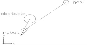
In 1986, Khatib proposed the Artificial potential field [2] for the first time. The basic principle is that the analogy to the magnetic field structure in a potential field (divided into the repulsive force field and gravitational field). The moving robot is subjected to the gravitational field of the target point in the potential field and keeps moving toward the target point. The moving robot is disturbed by the repulsion field of the obstacle in the process of moving toward the resultant force of repulsion and gravitation as shown in Fig. 1. Gradually approaching the target point, it will eventually construct an optimal or satisfactory path from the starting point to the target point. Get the shortest path is not necessarily, but it must be a smooth, safe path, the traditional artificial potential field method is a kind of micro control method [3, 4]. In the planning process, the robot determines the trajectory of the robot according to the exclusion of obstacles and the attraction of the target point.
Fig. 1Schematic diagram of traditional artificial potential field
2.1. Definition of artificial potential field method
The definition of the artificial potential field is as follows:
where UG(X) refers to the gravitational field at the target location and UO(X) refers to the repulsive field of the obstacle. The definition of gravitation and repulsive forces correspond to the negative gradient of the gravitation field and the repulsive force field respectively. According to the space dynamics equation and the Lagrange equation, the force of the artificial potential field on the robot F(x) can be deduced as follows:
where FG(X) refers to the gravitation of the target position to the robot, and FO(X) refers to the repulsive force of the obstacle to the robot.
2.1.1. Definition of repulsive force field
where kO is repulsive force coefficient, |X-X0| for the distance between the robot and obstacles, C0 is the robot’s maximum distance to the obstacle. When the distance between the robot’s current location and the current position of obstacles is greater than this value, the robot is no longer affected by obstacles, and the value depends on the actual situation of the obstacle, the robot and the target point. When the distance between the robot and the obstacle is greater than or equal to C0, the robot will no longer be affected by obstacles. Accordingly, the repulsive force formula of robot is:
2.1.2. Definition of gravitational field
where kG is the gravitational potential field parameter, X0 is the target point position. the gravitational force can be expressed as:
The larger the distance between the robot and the target point in the above formula, the more attractive the target point is to the robot.
2.2. Defects of traditional artificial potential field method
When the traditional artificial potential field method is used for path planning, the following problems are present:
1. The robot uses virtual repulsion and gravitation to control the movement direction of the robot during path planning. If the distance between the two obstacles is very close, there may be a problem that the robot cannot pass the narrow channel [5].
2. When there is an obstacle in the vicinity of the target point, there may be situations where the virtual repulsion is greater than the attraction of the target point, causing the target to be unreachable, namely, the target unreachable problem (GN-RON).
3. In the process of path planning, the resultant force of virtual repulsion and gravitation is zero and does not reach the target point [6]. The robot will fall into the local minimum point to stop the movement, resulting in the failure of path planning, which is the local minimum problem.
3. Improved artificial potential field method
3.1. Improve the potential function
In the process of popularizing artificial potential field method, it is very important to solve two problems of traditional artificial potential field. In response to these two problems, domestic scholars have produced many new solutions. Li Xiaoli proposed stochastic disturbance and gait growth half-fold method [7], Fan Hong of Zhejiang University proposed a directional search method [8]. Kunming University of Science and Technology, Liu Yi, put forward the introduction of the target point and the relative position of the robot to optimize the potential function of the method [9]. Shan Baoming et al, proposed a method of random escape and escape along the equipotential line [10], but the goal of random escape was not clear enough. The repulsion potential field coefficients are adjusted in real time by fuzzy controller, which proposed by Meng Rui [11]. To a certain extent, it improved the defects of artificial potential field method, but relies on the formulation of fuzzy rules, and the artificial potential field itself is an iterative algorithm, improved algorithms lead to increased planning time.
The above research methods have improved the local minimum problem of traditional artificial potential field method to some extent, but the effect is not particularly ideal. For two of the limitations of traditional artificial potential field method, this paper proposes to reconstruct the repulsion field when repulsion fields overlap, and when the mobile robot enters the local minimum range, improving the gravitational potential field function to solve the two problems of traditional artificial potential field method.
3.2. Reconstruction of repulsive force field
The traditional artificial potential field method determines the direction of movement of mobile robots by the force of repulsion force and gravity force of mobile robot. The path planning method, which relies on virtual repulsion and virtual gravitational force, easily leads to the mobile robot sink into the slot when there are non-convex obstacles in the path planning space (especially the U-shaped obstacles which facing the robot [12]) or narrow channel, cannot be passed.
3.2.1. Reconstruction method of repulsive force field
In this paper, we propose to reconstruct the repulsion field when the repulsion fields overlap each other to avoid the U-shaped repulsion field. This method can basically avoid the problem of robot path planning failure caused by the obstacle shape distribution. Methods as below:
When the repulsive fields overlap and the degree of overlap equals or exceeds the threshold S, the repulsive fields are superposed as connected repulsion fields. No matter how large the angle of the two repulsive forces between the two repulsive field intersections is, the obstacle is expanded and the middle part of the two obstacles is filled, so as to avoid the path planning between the two obstacles.
When repulsion fields overlap and the degree of overlap is less than threshold S, repulsion fields are not processed, allowing the path planning to be carried out between two obstacles.
3.2.2. Determination of threshold S
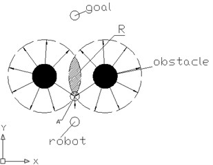
The degree of overlap is when two repulsive fields coincide, as shown in the shaded part of Fig. 2. When two repulsive force angles at the intersection of two repulsion fields are right angles and the resultant force of the point is zero, the overlap area is the overlap degree threshold S, obviously at this moment S can be determined by the position P of the intersection and the position of the two obstacles XO1, XO2. Reasoning is as follows:
Based on the formula for X, namely P position, then S can be obtained. The overlap threshold S can solve the problem of U-type obstacle and the problem that the robot cannot pass through the narrow channel.
Fig. 2The threshold S diagram
3.3. Analysis of local minimal problem of improved potential field function
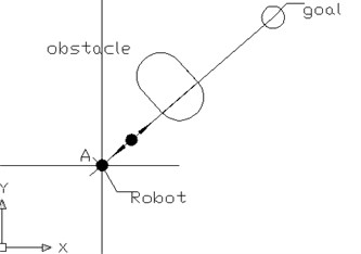
When the mobile robot is in the path planning process, it will encounter the situation of the robot, the obstacle, the target point of three points, as shown in the Fig. 3. According to the synthesis theorem of force, as the robot continuously moves towards the target point, the gravitational force generated by the gravitational field is opposite to the repulsive force generated by the repulsion field. Due to the increasing repulsion in the process of moving, the gravitational force keeps getting smaller, there must be a point where the gravitational and repulsive forces work together to zero. At this moment, the robot cannot move forward because of losing the goal of path planning, which indicates that the path planning fails.
Fig. 3The repulsion and gravitational collinear schematic diagram
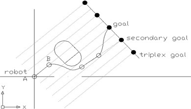
Improved algorithm proposed in this paper: When the robot falls into the local minimum problem, the target point is changed to the target line (which is the over-target point and is perpendicular to the obstacle and the moving robot). In this case, the robot path planning goal is a line. The target of path planning is temporarily changed to the target line and a series of feature points on the target line are selected as the target line instead. When the robot falls into a local minimum, the feature point closest to the target point is selected as the secondary target. Under the influence of the repulsion field, the mobile robot will move towards the secondary target point under the effect of the gravitational field of the secondary target point, and so on. Until inspection robot out of the current obstacles repulsive force field, the robot by the repulsive force is zero. After the mobile robot departs from the local minimum, the original target point and the gravitational field are restored and the path planning is continued. Diagram shown in Fig. 4.
Specific algorithms are as follows:
Step 1. Detect the robot into the local minimum.
Step 2. Change the target point to the target line, take the line close to the target point, and according to a certain distance distribution of the target point instead of the target line, and the secondary goal as a secondary target point to continue path planning, if the secondary goal plan into the local minimize, continue selecting triplex goals, and so on.
Step 3. Detect the influence range of the repulsion field from the current obstacle and move the robot away from the local minimum, then restore the gravitational field of the previous target point until the original target point and gravitational field are restored.
Step 4. Eventually the mobile robot will jump out of the local minimum and move to the target location.
Fig. 4Improved gravitational field schematic
3.4. Application analysis of improved gravitational potential function for target unreachable problem
When the distance between the target point and the obstacle is relatively close, there will be a situation where the repulsion field interferes with the gravitational field and thus the goal is not accessible. In this regard, this paper proposes the following improvements:
Step 1. Add a reverse repulsion field to the target point analogy as an obstacle, which is actually a gravitational field, and the size is equal to the influence range of the repulsive force field of the obstacle, in the opposite direction.
Step 2. When the robot moves near the target point, the robot will automatically find the best position and angle to the target point within the influence range of the improved reverse repulsion field until the distance between the detection point and the target point is within one step, and the default path planning is completed.
Improved gravitational field:
where kG represents the gravitational potential field parameter, XG is the target point position, kO is an adjustable parameter of repulsive force field, C0 represents the maximum distance between the robot and obstacle. The improved gravitational field follows the requirement that the potential field and its gradient proposed by Khatib and the resulting path in space should be continuous [2].
The gravitational field generated by this gravitational field is:
4. Simulation experiment
Simulation environment Settings as shown in Fig. 5, the moving range of the mobile robot is 30 m×30 m, where the box point represents the initial position of the mobile robot, the cross position represents the target position, the circle position is the position of the obstacle in the area. Mobile robot navigation task is to use the artificial potential field rules draw a path that allows the mobile robot to move from the starting point to the end point, and the robot will not collide with any obstacles while it is moving.
Fig. 5The simulation environment
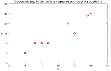
Fig. 6Simulation repulsion field diagram
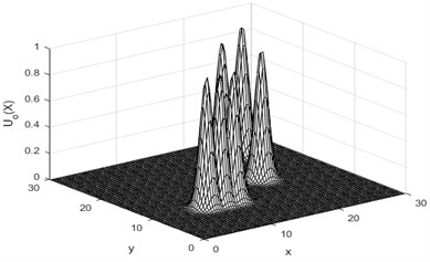
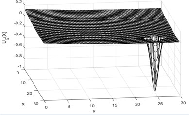
The repulsive field of the whole space caused by an obstacle is shown in Fig. 6. The peak height represents the magnitude of the repulsive force of the robot at this point. The improved gravitational field is shown in Fig. 7, without the influence of obstacles near the target point, which could cause the target unreachable phenomenon.
The repulsive field influence range map and the improved later superimposed field diagram of the gravitational field and the original repulsive force field are shown in Fig. 8, from which it can be seen that the gravitational field of the space obstacle and the target point are located. At this point will not lead to the phenomenon of unreachable, which caused by the presence of obstacles near the target.
Fig. 7Simulation of gravitational field diagram
When encountering the local minimum problem, the path planning of the robot extends the target point as the target line. In the simulation, a series of characteristic points are taken on the gravity line to replace the gravitational line and superpose with the original repulsion field. The comparison diagram and simulation results of the preset artificial potential field paths are shown below.
Fig. 9 is trapped in local minimum. Fig. 10 is that the mobile robot cannot pass the narrow passage between the two obstacles. Fig. 11 shows that the robot cannot reach the target point near the obstacle. Fig. 12 is improved Artificial Potential Field Path Planning. By the simulation results can be concluded that the improved artificial potential field method compared with the original artificial potential field method has greatly improved, better solve the local minimum problem, where there are obstacles in the near target, path planning can reach the target point, and from a more reasonable point of view and path to reach the target point, which is the biggest breakthrough in this article.
Fig. 8The superposition of the gravitational field and the repulsion field
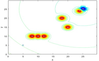
Fig. 9The robot is in a state diagram of a resultant force of zero
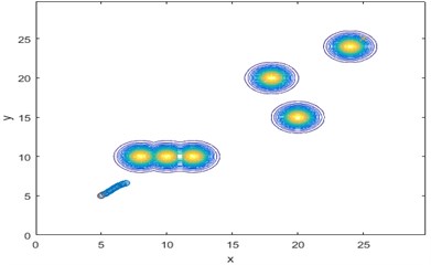
Fig. 10The robot cannot pass the narrow channel state diagram
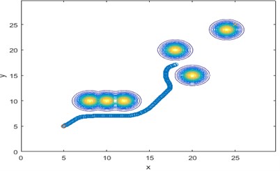
Fig. 11The robot cannot reach the target point near the obstacle
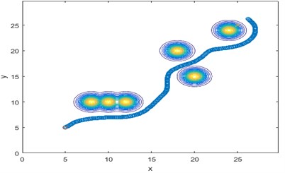
Fig. 12A state diagram of a robot using an improved algorithm to reach the target point at the most reasonable angle
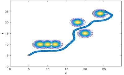
As shown in Table 1 is an improved algorithm to achieve a total time of 4.912 s path planning time. Compared with the original algorithm, not only the effect of path planning is obvious, but also the less time of the algorithm.
This article selects the improved path planning algorithm and the current hot bionic intelligent algorithm. Due to the gap between various intelligent algorithms is not large, the robustness, real-time and applicability of the algorithm are compared from two aspects of the effect of path planning and the time complexity of the algorithm.
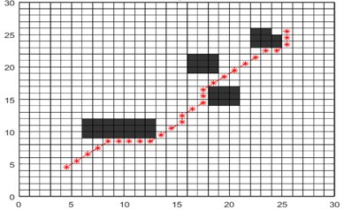
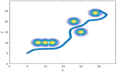
The path planning algorithm of the ant colony path planning algorithm as shown in Fig. 13(a) and the improved artificial potential field as shown in Fig. 13(b) are compared in the path planning of the same obstacle environment in 30 m×30 m. The starting point coordinate is (5, 5) and the target point coordinate is (25, 25). The paths planned by the ant colony path planning algorithm are both polylines and the planned paths are very close to the obstacles. Such a path for mobile robot navigation is very adverse, whether it is a home service robot or factory transportation environment of the mobile robot is not allowed, and the ant colony algorithm cannot find the target due to obstacles in the coordinates (24, 24) near the target point, finally it will stop near the target. For the improved artificial potential field method, the smooth planned path is conducive to acceleration and velocity control of the mobile robot. Whether in the home or in the factory environment has strong applicability, planning path and people thought that the ideal path is very consistent. Whether it is close to the obstacle or the obstacle near the target point, the obstacle is avoided at a very reasonable angle, and it is reasonable to have the obstacle coordinate point (24, 24) near the target point (25, 25). Due to the superposition of the improved gravitational field and the repulsive force field, the path of the mobile robot approaches the target point with the minimum field strength, approaches the target point at a reasonable angle while avoiding the obstacle reasonably, and finally reaches the target point.
Fig. 13Compare the path of the different algorithm
a)
b)
Table 1Running time of algorithm
Function block | Call times | Total time-consuming | Private use time |
Main | 1 | 4.912s | 1.921s |
Goal function | 189409 | 1.388s | 1.388s |
Obstacle function | 189409 | 1.019s | 1.019s |
Coutor | 4 | 0.119s | 0.012s |
Table 2Compare the time of the algorithm
Number of simulations | Traditional artificial potential field method | Ant colony intelligent algorithm | Improved artificial potential field |
1 | 16.655 | 69.788 | 18.516 |
2 | 15.14 | 70.491 | 18.111 |
3 | 13.344 | 70.015 | 18.563 |
4 | 13.786 | 71.625 | 19.382 |
5 | 13.745 | 71.268 | 20.622 |
6 | 15.9 | 67.958 | 17.833 |
7 | 13.133 | 71.026 | 17.734 |
8 | 13.939 | 69.449 | 19.101 |
9 | 17.133 | 69.162 | 18.839 |
10 | 13.005 | 70.321 | 17.511 |
Mean | 14.578 | 70.110 | 18.621 |
It can be seen from the table that the average time of ten times for the traditional artificial market method to simulate is 14.578 s and the average time for the improved artificial potential path planning algorithm is 18.621 s. The average time is only 4.043 seconds more than the traditional artificial potential field. The navigation effect has basically improved the defect of the artificial potential field, and the real-time performance of the algorithm can be guaranteed. Intelligent ant colony algorithm in the same environment for an average of 70.110 s, compared with the time-consuming 3.77 times of the improved algorithm, it is obvious that the improved artificial potential field method has the real-time advantage which others cannot match in real-time algorithm.
5. Conclusions
In this paper, we focus on the two problems of traditional artificial potential field: the target non-reachable problem and the minimum value problem. Proposed to transform the gravitational field function to solve the target unreachable problem (the target point as an obstacle, add a reverse repulsion field, thereby reducing the impact of obstacles near the target point), proposed in the robot encountered a minimum problem, the target point into a target line planning method. The simulation results show the effectiveness of this method, and the disadvantage of this paper is that the speed and path smoothness are not considered in the path planning.
Given all this, this paper introduces the defects of U-shaped obstacle problem, Local minimum, GNRON. Repulsive force field reconstruction is used to reduce the U-shaped obstacles and to solve the problem that cannot pass narrow channel, by changing target point as the target line to solve the local minimum problem, for GNRON we use “Reverse repulsion force field” to solve.
The improved algorithm, the traditional artificial potential field method and the ant colony intelligent algorithm are compared and analyzed from the planned path and the algorithm time, which shows that improved algorithm described in this article better solved the problems that exist in the traditional artificial potential field method application. The improved artificial potential field described in this paper has a strong algorithm robustness and applicability under the premise of ensuring the real-time performance of the algorithm. It can be applied to indoor mobile robot navigation, UAV navigation and other aspects, and can better achieve the obstacle avoidance task and navigation task.
References
-
Yuanyuan W., Rujing W., et al. The designing and comparing of multi diagnosis and reasoning methods. Computer Engineering and Applications, Vol. 41, Issue 2, 2005, p. 57-58.
-
Khatib O. Real-time obstacle avoidance for manipulators and mobile robots. International Journal of Robotics and Research, Vol. 5, Issue 1, 1986, p. 90-98.
-
Jingkai W., Yuancan H., et al. Anti-collision path planning for mobile robot based on potential field method. Robot Technology, Vol. 23, Issue 2, 2007, p. 228-230.
-
Xiaodong Z., Qingchun M. Optimal path planning in complex environments based on optimization of artificial potential field. Robot, Vol. 20, Issue 4, 2003, p. 623-627.
-
Ying L., Hong S., Huang J., et al. The new environment model building method of penetration mission based on the artificial potential field approach. International Multi-Disciplinary Conference on Cognitive Methods in Situation Awareness and Decision Support, 2012, p. 121-124.
-
Zaixin L., Longxiang Y., Jinge W. Soccer robot path planning based on evolutionary artificial filed. Advanced Materials Research, Vol. 562, Issue 8, 2012, p. 955-958.
-
Xiaoli L., Jing X., et al. An evolutionary artificial potential field method used to obstacle-avoidance planning of multiple mobile robots. Computer Engineering and Applications, Vol. 17, 2005, p. 56-58.
-
Hong F. The potential-field based collision-free-path-planning approach for point robot. Bulletin of Science and Technology, Vol. 7, 2003, p. 258-287.
-
Yi L., Zhang Y. Study of local path planning of mobile robot based on improved artificial potential field method. Modern Machinery, Vol. 6, 2006, p. 48-49.
-
Baoming S. Simulation study on mobile robot path planning based on improved potential field. Information Technology, Vol. 1, 2014, p. 170-173.
-
Rui M., Weijun S., et al. Mobile robot path planning based on dynamic fuzzy artificial potential field method. Computer Engineering and Design, Vol. 7, 2010, p. 1558-1561.
-
Yi Z., Tao Z., Jingyan S. Study on the local mini-ma problem of path planning using potential field method in unknown environments. Acta Automatica Sinica, Vol. 36, Issue 8, 2010, p. 1121-1130.
