Abstract
Multi-degree-of-freedom motors have attracted more and more attentions, and the liquid suspension multi-degree-of-freedom PM motor is regarded as one of the research hotspots of new kind of electrical machine. In order to further optimize the structure of liquid suspension permanent magnet synchronous multi-degree-of-freedom motor and improve the stability of the operation, the mode force analysis of the motor's component is carried out. The characteristics and basic structure of the motor are introduced, and the principle and rules of the motor resonance are expounded in detail. Based on the theory of mechanics, the mode of the motor spherical shell is studied and calculated. By finite element analysis, the modal changes of stator shell under static and energized conditions are calculated and the comparison is made. Then, the 2nd order modal deformation of the spherical shell is monitored by hammering and sensor with the measured data obtained and compared with the finite element simulation. The solid mechanical structure of the claw stator core is analyzed so that the stress distribution and deformation displacement distribution are obtained. The results of the simulation and analysis provide the reference for the optimal design of this kind of motors or actuators.
1. Introduction
With the development and progress of modern society, the potential use of multi-degree-of-freedom permanent magnet motors has been more and more widely, which has a very bright foreground in the aero space, military and other aspects. The multi-degree-of-freedom motor can be drive to rotate and translate in more than two axises in three dimensional spaces. Compared with the several single degrees of freedom of motors, multi-degree-of-freedom motor has a wider application range, smaller size, cost reduction, improvement of drive performance. The liquid suspension multi degree of freedom motor is a research hotspot of new multi degree of freedom motor [1-3].
The multi-degree-of-freedom permanent magnet motor usually adopts the traditional mechanical bearing connection structure, which has the disadvantages of friction loss and high heat generation [4, 5]. These reasons lead to the limitation of the application of the motor. The dynamic characteristics of the rotor will be affected by the friction resistance of the mechanical bearing, which will lead to the reduction of the motor efficiency and the service life [6]. In addition, the magnetic field of the traditional multi-degree-of-freedom permanent magnet motor is easy to out of control. The motor is difficult to operate in suspension mode, which is difficult to improve the control accuracy. In order to solve the problem of multi-degree-of-freedom permanent magnet motor with using traditional bearing structure, researchers have increased the research on the bearing structure and driving mode of the multi-degree-of-freedom permanent magnet motors [7, 8]. The purpose of this work is to reduce the motor energy loss, reduce the motor noise, improve the motor dynamic performance and control accuracy. Multi-degree-of-freedom permanent magnet motors are currently developed towards the directions of more efficient, environmental protection, high precision positioning, more easily to integrate and miniaturization direction [9].
Based on the above, the PM hybrid suspension driven multi-degree-of-freedom motor has been proposed. The liquid suspension hybrid electric motor has absorbed the advantages of magnetic suspension bearingless motors, conventional PM synchronous motors and a variety of multi-degree-of-freedom permanent magnet spherical motors. The rotor of the motor is suspended in the liquid within the stator shell and driven by the stator coils. Suspension and motion of the rotor are also driven by the stator coils. The innovative liquid suspension structures are adopted by this motor, which can greatly reduce the friction loss and save energy. The accuracy and flexibility of motor control can be improved by hybrid driving mode. The motor can be used in the field of robotics and human bionics, which need precise positioning in the field of free movement [10].
During the operation of permanent magnet synchronous motor, the vibration and deformation displacement of the motor modules excited by electromagnetic force which are the main sources of the mechanical deformation of the motor [11]. The deformation and noise are produced by the vibration and rotation of the multi-degree-of-freedom motor, whose process is very complicated. The small-parameter method of Poincare and the KBM asymptotic method are usually adopted, which usually is very effective for solving single-degree-of-freedom and multi-degree-of-freedom system, and greatly simplifies the stability of the periodic solution. The various forms of multiscale methods are being systematized through Nagfeh and Mook, and the nonlinear vibration problem of some continuum systems is solved effectively [12, 13].
In order to further optimize the structure of the motor, a vibration of a liquid suspension hybrid drive multi-degree-of-freedom motor in a complicated multi-physics field is studied.
2. Structure of motor
2.1. Composition of structure
The liquid suspension hybrid drive multi-degree-of-freedom permanent magnet synchronous motor mainly includes the rotor, stator coil, spherical shell and the liquid oil film between two layers of spherical shells. In the multi-degree-of-freedom motor, the mechanical bearing between the stator and rotor of the motor is different from the traditional motor structure. The motor is filled with oil film between the stator shell and the rotor, and the rotor is suspended in the liquid. In the way, the friction wear of the motor can be greatly reduced, which is more flexible and applicable to be controlled.
According to different requirements, the motor can be divided into output shaft structure and non-output shaft structure. The non-output shaft is also called the rotor embedded structure. The difference between them is that the oil film structure of the latter is a complete hollow spherical structure, as shown in Figs. 1 and 2.
Fig. 1Model with non-output shaft
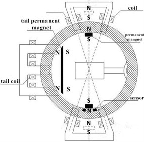
Fig. 2Model with the output shaft
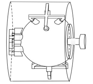
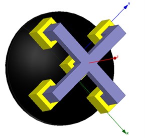
A large range adjustable permanent magnet is embedded in the vertical direction of the rotor shell, and a single stage fine tuned permanent magnet is embedded in the tail. The output shaft is fixedly connected with the permanent magnet. There is a fine motion coil system composed of 5 coils and cores at the end of the spherical shell [14]. The hybrid drive mode is adopted by multi-degree-of-freedom permanent magnet synchronous motor. By controlling the magnitude and direction of the coil currents, the large range motion and fine deflection motion of the rotor can be achieved. In the control process, a large range motion control method is used. If the control accuracy cannot be achieved, then the fine control system is used to fine tune the rotor to achieve the control accuracy. The control accuracy and efficiency can be improved to the greatest extent through this control mode. The rotation and deflection of the motor do not affect each other. The detailed arrangement of structure can be shown in Figs. 3 and 4.
Fig. 3Structure of the large motion adjustment
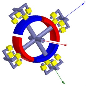
Fig. 4Structure of the small motion adjustment
2.2. Modeling of the motor
In the established model, the embedded shaft structure is selected. The stator shell and the rotor are built into two complete spherical structures. According to the structure which is mentioned above, the assumption of a modeling process can be shown as follows: 1) ignore the magnetic circuit saturation; 2) during the research of magnetic field, ignore the eddy current effects caused by magnetic field changes; 3) the magnetic field created by the energized coils only has effects on the rotor magnetic poles which are nearby the coils. The magnetic field has less effects on rotor magnetic poles which is not adjacent to the coils so that the leakage magnetic field can be ignored; 4) the magnetic material is isotropic medium. Detailed parameters are listed in Table 1.
Table 1Detailed parameters
Name | Value |
The radius of stator shell / mm | 21 |
The outside diameter of large range permanent magnet / mm | 18 |
The inner diameter of permanent magnet / mm | 17 |
The outer diameter of rotor shell / mm | 19 |
The gap of permanent magnet / mm | 2 |
3. Theoretical analysis of the vibration
3.1. Principle of resonance
Resonance is a case where a physical system vibrates at a given frequency in the greater amplitude than other frequencies, which is called the resonance frequency. During the operation of multi-degree-of-freedom permanent magnet motor, the coupling calculation of electromagnetic field, solid mechanics and solid heat transfer are involved, and the coupling and vibration noise produced by operation are more complex [15].
Before investigating the resonance law and coupling, the correct model is set up and the electromechanical coupling is realized. The interaction law and engineering application of electromechanical coupling analysis are studied, and the corresponding material is selected to view the intrinsic properties.
When the multi-degree-of-freedom PM motor in operation, the electromagnetic resonance will be occurred. Under certain frequencies, the multiple modal resonances are excited by electromagnetic resonance at the same time. To stimulate multiple resonances, it needs to satisfy two aspects: 1) it is necessary to satisfy its mathematical relation; 2) the modal of the system is required to have a proper coupling relationship [16]. Therefore, the coupled vibration study of the motor is essential.
3.2. Experimental principles
The sensors are used to monitor the modal changes of the stator shell. The modal analysis experiment is carried out on the stator shell of the multi-degree-of-freedom motor and the natural frequency of the stator is studied by the modal experiment. Compared with the data of the stator modal displacement which measured by FEM, the accuracy is verified. Because the stator of the motor is spherical, it chooses the 2nd order mode of the stator shell as the object of experiment and calculation.
In the experimental platform, the single point excitation of hammer method is applied. The force sensor is mounted on the hammer head to measure the excitation signal [17]. This experiment is used to detect the force deformation of the stator shell under the two order modes. The signals of displacement and deformation are returned to the computer through the sensor, and the analysis is carried out, which is compared with the data of the modal deformation of the stator shell calculated by FEM. The data is imported into the MATLAB, which directly presents the 2nd order modal changes of the stator.
3.3. Coupling of magnetic field and solid
After the main coil of the motor and the fine coil system are energized, since the coils are fixed on the iron cores, the magnetic domain of the magnetic material rotates along the magnetic field under the action of the external magnetic field. The direction of the magnetization tends to be consistent, which leads to the elongation or shortening of the core length along the direction of the magnetic force line, thus producing the magnetostrictive stress within the core [18, 19]. The magnetostriction stress of the stator core of the motor is calculated by the elastic mechanics method. As the motor is energized, the coils generate heat to make the coils and cores for further deformation. The phenomenon of magnetic structure coupling is the main phenomenon of the resonance of the motor. Therefore, in the research of motor structure system, it is also an important content to discuss the deformation caused by the force produced by the iron core after the coils are energized. Therefore, the magnetic field of the motor should be analyzed firstly, which is different from the calculation principle of two-dimensional static magnetic field. The method of three-dimensional static magnetic field calculation is the edge method, that is, the edges of meshing elements are the degrees of freedom for the solution of amount of field parameters.
The magnetic field equations of the motor windings are shown in Eq. (1):
where A(Ax, Ay, Az) is the magnetic vector and the J(Jx, Jy, Jz) is the current density vector; B(Bx, By, Bz) is the magnetic induction vector; E is the electric field intensity; ∇2 is Laplace Operator; ∇ is Hamiltonian operator. By using the method of separation of variables, the internal and external windings are taken into account, and the magnetic induction intensity is expressed as Eq. (2):
where Gki is the expression of the coordinate function and the current density, i= 1, 2, ..., 6.
After the above Eq. (2) calculates the magnetic field, according to the principle of classical mechanics, the differential equations of vibration in the system of three degrees of freedom linear vibration system, such as Eq. (3) are obtained:
where M mass matrix is in the matrix and C is a damping matrix; K is the stiffness matrix; {x''} is the acceleration vector; {x'} is a velocity vector; {x} is the displacement vector; F(t) is static load. In the present structural analysis, the amount of time variation is neglected, and the Eq. (3) can be simplified as Eq. (4):
According to the basic principle of magneto elastic mechanics, the magnetostrictive stress and magnetostrictive strain are linear; the magnetostrictive stress can be expressed as Eq. (5):
where σ is the magnetostrictive stress and the D is an elastic tensor; ε is Magnetostrictive strain.
4. Calculation of vibration modal
4.1. Coupling of magnetic and solid
When the motor is stationary, the shell of the stator should be selected and the parameters should be obtained. Because the model is a multi-degree-of-freedom permanent magnet synchronous motor, the stator shell approximation can be regarded as a hollow spherical shell, so only a spherical shell model is needed to illustrate the stator. In the modal analysis, the natural frequency of the model is analyzed. The expression of the intrinsic frequency A is as shown in Eq. (6):
where m is the equivalent mass of the object; k is the equivalent stiffness of the model. By establishing finite element model of stator of the motor, the changes of the stator modal parameters are observed. The 1st order and 2nd order modal diagrams of the stator are shown in Figs. 5 and 6.
The modal analysis of the spherical shell of the stator is carried out in the state of complete free condition. In the finite element simulation software, the mode changes of the first six orders of the stator spherical shell are respectively intercepted under without any constraints.
Since the vibration displacement of the stator surface caused by the radial electromagnetic force is inversely proportional to the 4th mode of the spatial order, the contribution of the first four orders model electromagnetic force to the vibration and noise is usually considered.
It can be seen from Figs. 5 to 6 that the modal deformation of the stator shell is matched with the force wave distribution of each order. Here, the 3rd order model is intercepted, and the 3rd order modal parameters of the stator are obtained, as shown in Fig. 7.
Fig. 5The 1st mode of stator
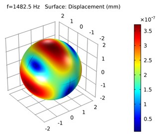
Fig. 6The 2nd order mode of stator
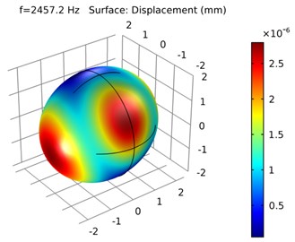
Fig. 7The 3 order mode of the stator
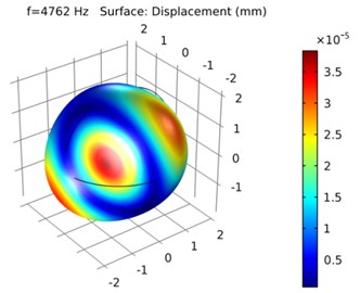
4.2. Influence of electromagnetic force on vibration modes
During the operation of the motor, the constraints in the surface of the stator shell are naturally formed after the coils are energized. The influence of coil winding on the modal frequency of the motor has been a difficult problem in the modal analysis of the motor. The electromagnetic force generated by the coils will also have some influence on the modal deformation of the motor stator [20, 21].
The whole motor is different from the natural frequency of the stator shell, so only the modal analysis during the operation of the motor is needed to see the displacement and deformation of the stator shell and compared with the modal analysis of single stator shell. The vibration displacement of the surface of the spherical shell can be calculated by modal superposition method [22]. The amplitude of m-order vibration displacement is generated by radial force wave of the space m-order, which can be expressed as Eq. (7):
where Dsi is the stator diameter and M is stator quality; Prm is the amplitude of radial force wave in space m order; fm is the modal frequency of the stator m order mode; hm is a structure amplification factor, which can be expressed as Eq. (8):
Here, the order φm is the m-order modal damping, and f is the m-order electromagnetic force frequency.
There are the modal deformation diagrams of the stator shell and the core coils when the motor is running, as shown Figs. 8 and 9. Compared with Figs. 5 and 6, it can be seen that the modal response of the first three orders of the spherical shell is the inherent and overall characteristics of the elastic material under without any constraint. Through the finite element method, the main modal characteristics of its structure material are derived for the stator shell without external force effects. When the coil is electrified, the stator shell will be affected by the electromagnetic force, so it is necessary to study the modal changes of the stator in the operation process.
As shown in Fig. 8, the first order mode of the whole motor is shown. It can be seen that the natural frequency of the motor is about 1760 Hz. From the deformation distribution, it is found that in the 1st order mode of the motor, the stator has a great influence on the modal frequency of the model. The deformation of the stator core and the coils is small, most of which are concentrated in contacting with the stator shell. It also shows that the motor does not have electromagnetic resonance at this frequency.
Fig. 8The 1st order mode in operation
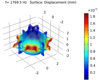
As shown in Fig. 9, the 2nd order mode of the motor under operation is shown. Compared with the 1st order mode, the stator shell and the iron cores have large deformation, and the iron cores will also appear a certain deviation phenomenon. Because the cores and the frequency of the 2nd mode of the stator shell are close to each other, and the 2nd modal frequency of the overall structure of the motor is relatively low and more likely the electromagnetic resonance will occur near that frequency, which will increase the stress and deformation of the motor.
Fig. 9The 2nd order mode in operation
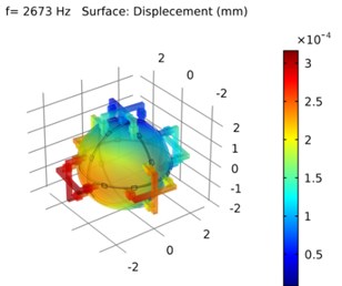
Fig. 10The 3rd order mode in operation
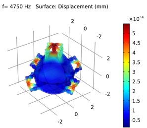
Fig. 10 shows the 3rd order mode change of the motor. As can be seen the electromagnetic resonance is eliminated when the motor runs and the frequency reaches to 4750 Hz. In this frequency range, the force deformation of the motor cores and the coils are obviously greater than the deformation of the stator shell.
5. Experimental and data analysis
Fig. 7 shows the 2nd order mode plane diagram of the stator. It can be seen that there are two maximum points in the lower half part of the plane, which are respectively set to –90° and 90°.
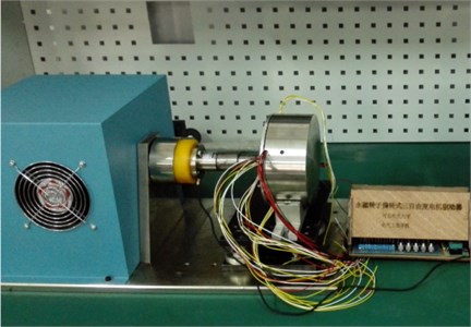
The sensor and stator are combined to form an experimental platform, as shown in Fig. 11. Using the force hammer to strike the stator shell, the vibration frequency and deformation displacement on the stator shell are sent back to the computer by sensors.
Fig. 11The experimental platform
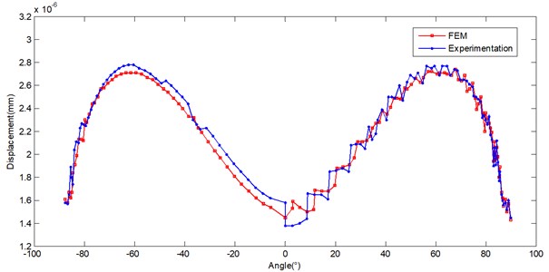
The FEM data is imported into the calculation software and the simulated data is fitted. It can be seen that the curve is approximately sinusoidal wave form. The positions are in ±60°, and the displacement can be reached to 2.8×10⁻⁶ mm, as shown with the red line in Fig. 12.
When the change of the modal displacement of the stator shell is measured, 50 knocking points are selected near the equator of the stator shell to knock on each exciting point. Through the sensor connected to accelerometer and force hammer, every percussion point data and displacement signal are sent back to the computer for data collection and processing. Since it is difficult to ensure the size of the force each time when the force hammer is struck, only the excitation signal with frequency of about 2400 Hz is selected. The data is analyzed and collected by using the analysis system, as shown with the blue line of Fig. 12.
Fig. 12Comparison of FEM and Experimentation
6. Stress deformation of stator core
Since the coils are fixed on the stator of the motor by the stator cores, the electromagnetic field will be generated after the coils are electrified. The stator core will be affected by the electromagnetic force of the electromagnetic field and lead to the phenomenon of magnetostriction in the core.
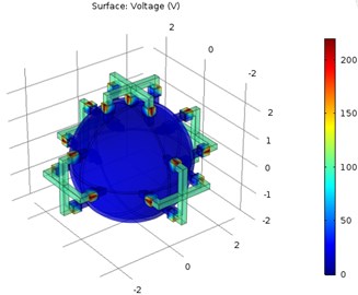
In order to predict whether the change of electromagnetic field will affect the normal operation of the motor after the energization, the method of finite element simulation is used to test the influence of electrifying coils on the motor. As shown in Fig. 13, the electric potential diagram of the motor after the coils are electrified is given.
Fig. 13The potential diagram
In order to obtain the force conditions of the claw type iron cores in the finite element simulation, the influence of the electromagnetic and temperature on the claw type iron core structure is studied. In the finite element simulation, the parts of the contact between the cores and the stator surface are set as the boundary conditions, which is the fixed constraints. After the coils are electrified, the stress caused by the claw cores of the motor and the displacement caused are shown in Figs. 14 and 15.
Fig. 14The distribution of equivalent stress
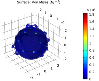
Fig. 15The displacement distribution
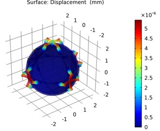
As can be seen from Figs. 14 and 15, the stress of the stator cores is mainly concentrated on the center position of the iron cores and the position of the fixed coils. There are four supporting points on the iron core of the fixed coil around the motor, and there is no support column in the center, so the coils will be deformed when the coils are electrified. The maximum equivalent stress on the iron core is 1.8×10⁹ N/m2. The position of the deformation produced by the force of the motor cores is the same as the direction of the iron core with the stress direction. The maximum displacement is only 5.44×10⁻⁶ mm, which has little influence on the motor. Through a series of simulation data, it can be seen that the stress of the stator cores is larger in the normal operation of the motor. Therefore, when the motor is optimized, it is necessary to increase the strength of the stents, providing data guarantee for further motor design.
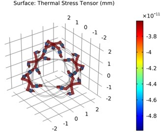
After the coils generate electromagnetic field under energizing, the change in the temperature of the coil winding and the motor temperature rise phenomenon need consideration. Therefore, it is necessary to study the influence of temperature change on the claw type iron cores of the motor. As shown in Fig. 16, when the claw type iron cores are only changed by the temperature, the deformation situation is approximately the same as the deformation of the stress under electrified, concentrated on the central position of the cores and the position of the fixed coils. The maximum equivalent stress is 3.61×10⁻¹¹mm. The effect of coils heat production on the stress and deformation of iron cores are in very small number during the operation of the motor.
Fig. 16The deformation of thermal strain
7. Conclusions
This paper mainly focuses on the liquid suspension multi-DOF permanent magnet synchronous motor, and introduces the structure and working principle of the motor. The motor is modeled by the finite element analysis platform intuitively. Based on the three modules of electromagnetic, solid mechanics and solid heat transfer, the modal analysis of the motor stator shell is carried out, and the change pattern of the three modes is obtained. When the motor is operated normally, the coils are electrified to produce the electromagnetic force. The modal change diagram of the stator shell and core is observed with the operation state of the motor, and the first three modals' changing are selected, and compared with the stator shell modal analysis under static state. The results show that the electromagnetic resonance may occur in the low frequency operation of the motor after the coils are electrified. In addition, the modal variations of the stator cores and the coils are smaller, most of which are concentrated on the parts of the stator shell. When the frequency is raised, the electromagnetic resonance is eliminated, and the force deformation of the motor cores and coils are obviously greater than the stator shell.
On this basis, the experimental test of stator modal deformation is implemented. The deformation and displacement of the stator are monitored by hammering method and sensor, and the deformed data of 2nd order model at the equator. When the data is connected in a curve, it is approximately as the sine curve, which is consistent with the data obtained by the FEM to verify its accuracy.
In the case of the coil is electrified, a simulation about certain stress and the deformation of the motor structure is carried out. The results show that the deformation and displacement of the coils are not obvious, but the stress of the stator core is large. Therefore, the strength of the stents should be increased for the motor design. The results of calculation and analysis provide theoretical basis and data for the optimal design and control of the motor.
References
-
Li Z., Wang Q. J. The present research and development and development situation of permanent magnet spherical motor of multi-dimensions. Small and Special Electrical Machines, Vol. 33, Issue 10, 2006, p. 7-11.
-
Li Z., Wang Y. T., Ge R. L., Zhao G. H. The summary and latest research of PM spherical M-DOF motor. Micromotors, Vol. 44, Issue 9, 2011, p. 66-70.
-
Lee K. M., Vachtsevanos G., Kwan C. Development of a spherical stepper wrist motor. Journal of Intelligent and Robotic Systems, Vol. 1, Issue 3, 1988, p. 225-242.
-
Zhang F. G., Du G. H., Wang T. Y., Liu G. W. Review on development and design of high speed machines. Transactions of China Electrotechnical Society, Vol. 31, Issue 7, 2016, p. 1-18.
-
Li Z., Xing D. H., Nie W., Wang Q. J. Magnetic field and torque analysis of hybrid driven permanent magnet multi-DOF motor. Small and Special Electrical Machines, Vol. 44, Issue 11, 2016, p. 18-22.
-
Lim C. K., Chen I. M., Yan L., Yang G. Motion generation methodology of a permanent magnet spherical actuator. IEEE/ASME International Conference on Advanced Intelligent Mechatronics, 2009, p. 1377-1382.
-
Guo X. W., Wang Q. J., Li G. L. Research and development of multi-degree-of-freedom permanent magnet spherical motor’s control strategy. Small and Special Electrical Machines, Vol. 2, 2011, p. 72-76.
-
Wang J. B., Wang W. Y., Jewell G. W. A novel spherical permanent magnet actuator with three degrees-of-freedom. IEEE Transactions on Magnetics, Vol. 34, Issue 4, 1998, p. 2078-2080.
-
Liu J. B., Huang W. Q., Zhao C. S. Development and application of spherical ultrasonic motor with multi-degree of freedom. Journal of Vibration Measurement and Diagnosis, Vol. 21, Issue 2, 2001, p. 85-89+147.
-
Li Z., Lun Q. Q., Xing D. H., Gao P. F. Analysis and implementation of a 3-dof deflection type pm motor. IEEE Transactions on Magnetics, Vol. 50, Issue 11, 2015, p. 8207304.
-
Cameron D. E., Lang J. H., Umans S. D. The origin and reduction of acoustic noise in doubly salient variable reluctance motors. IEEE Transactions on Industry Application, Vol. 28, Issue 6, 1992, p. 1250-1255.
-
Nayfeh A. H., Mook D. T. Nonlinear Oscillations. Weloy Intersienec, 1979.
-
Qiu J. J. Nonlinear Vibration on Coupled Mechanical and Electric Dynamic Systems. Science Press, Beijing, 1996.
-
Li Z., Xing D. H. Analysis of magnetic field and oil film bearing characteristics of a novel hybrid drive multi-DOF permanent magnet motor. 11th Conference on Industrial Electronics and Applications, 2016, p. 239-244.
-
Qiu J. J. Investigation coupled mechanical and electrical vibration and couple magnetical and solid vibration of electrical machine. Proceedings of the CSEE, Vol. 22, Issue 5, 2002, p. 109-115.
-
Lin Fu., Zuo S. G., Deng W. Z., Wu. S. L. Modeling and analysis of electromagnetic force, vibration and noise in permanent magnet synchronous motor considering current harmonics. IEEE Transactions on Industrial Electronics, Vol. 63, Issue 12, 2016, p. 7455-7466.
-
Xie Y., Wang Y., Lü S., Ge H. Y., Liu H. S. Modal calculation and test of small asynchronous motor. Transactions of China Electrotechnical Society, Vol. 30, Issue 16, 2015, p. 1-9.
-
Yang H. D., Chen Y. S. Influence of radial force harmonics with low mode number on electromagnetic vibration of PMSM. IEEE Transaction on Energy Convers, Vol. 29, Issue 1, 2014, p. 38-45.
-
Xia C. L., Li H. F., Shi T. N. 3d magnetic field and torque analysis of a novel Halbach array permanent-magnet spherical motor. IEEE Transaction on Magnetics, Vol. 44, Issue 8, 2009, p. 2016-2020.
-
Park K. W., Cho G. W., Kim Y. T., Kim G. T. Optimum design of barrier to reduce resonance and displacement analysis of IPMSM. Vehicle Power and Propulsion Conference, 2012, p. 252-257.
-
Wang T. Y., Wang F. X. Vibration and modal analysis of stator of large induction motors. Proceedings of the CSEE, Vol. 27, Issue 12, 2007, p. 41-45.
-
Lin F., Zuo S. G., Mao Y., Wu S. L., Deng W. Z. Semi-analytical model of vibration and noise for permanent magnet synchronous motor considering current harmonics. Transactions of China Electrotechnical Society, Vol. 32, Issue 9, 2017, p. 24-31.
About this article
This work is supported by the National Natural Science Foundation of China (No. 51577048, 51637001, 51107031), the Natural Science Foundation of Hebei Province of China (No. E2018208155), the Overseas Students Science and Technology Activities Funding Project of Hebei Province (No. C2015003044), the National Engineering Laboratory of Energy-saving Motor and Control Technique, Anhui University (No. KFKT201804), Key Project of Science and Technology Research in Hebei Provincial Colleges and Universities.

