Abstract
The influence of complex pre-stress on the circular thin plate is investigated in this study to solve the non-uniform stress distribution problem. The differential equation of the circular plate with complex pre-stress distribution is derived based on the strain-displacement equation. The analytical method of free vibration for the circular plate with complex pre-stress distribution is proposed, in which the complex pre-stress and displacement function of the circular plate are expanded into the cosine trigonometric series. The influence of the different types of welding residual stress distribution on the natural frequency and the mode shape of the circular plate structure is compared. Finally, the effectiveness of the proposed model is verified through finite element method.
1. Introduction
The circular thin plate structure is widely used in marine, aerospace, and automotive engineering. A large amount of research has been devoted to study the vibration problem of the circular plate with theoretical analysis, numerical calculation, and experimental investigation [1, 2]. Axisymmetric vibration problems [3, 4] and nonlinear vibration problems [5-8] have become hot research topics. The pre-stress or initial stress usually exists in the structure before it undertakes the work loading. Pre-stress includes welding residual stress, assembly stresses, and hydrostatic pressure. These types of pre-stress are defined as complex pre-stress. The influence of pre-stress on structural strength and fatigue has been investigated [9]. The existence of pre-stress stress provides a considerable influence on the local and global stiffness matrices and thus on natural frequencies, mode shapes, and dynamic response [10, 11]. Many studies have focused on the uniformly distributed pre-stress problem, such as hydrostatic pressure, water-pressure-deduced stress, or fluid-velocity-based stress [12, 13]. However, most of the existing studies are limited to a uniform or specific pre-stress distributions problem [14, 15]. Welding residual stress is a common non-uniform distribution pre-stress in engineering design and construction. The traditional solution is no longer suitable to solve non-uniform pre-stress distribution problems [16-18]. Moreover, few works have stated the solution for the vibration problem of a circular plate with welding residual stress distribution despite its frequent existence in structure. Thus, analyzing the vibration characteristic of a circular plate with non-uniform pre-stress distributions is necessary.
The present study aims to provide an efficient analytical method for a circular plate structure with non-uniform pre-stress distributions. The proposed method can analyze the dynamic behavior of the arbitrary pre-stress distribution problems of the circular plate, such as with/without pre-stress distribution, local area or overall pre-stress distribution, and non-uniform pre-stress distribution. The analytical method indicates that the complex pre-stress, regardless of its distribution or value, is expressed as a special series that can state almost all of the pre-stress distributions and achieve partial decoupling among the structural modes in the vibration equation.
This remainder of this paper is organized as follows. Section 2 demonstrates the basic model of the circular plate pre-stress. Section 3 presents the motion differential equation for the circular plate. Section 4 provides the solution procedures of the differential equation. Section 5 validates the influence of complex pre-stress on the dynamic characteristics of the circular plate, such as natural frequency and mode shape, with a numerical analysis. Finally, Section 6 provides the concluding remarks.
2. Pre-stress model
2.1. Pre-stress model in circular thin plate
An elastic isotropic thin plate is used to establish a pre-stress distribution model, in which the pre-stress value varies with different locations. Some assumptions are made as follows. A fluid-structure coupling problem is omitted. The pre-stress and stress caused by vibration satisfy the linear superposition principle. Vibration satisfies the small elastic deformation condition. Stress is uniformly distributed in the thickness direction. Structural stress is perpendicular to the cross section in vibration. Structural pre-stress remains constant during vibration.
A polar coordinate system Orθ is established, in which the coordinate origin is located at the center of the neutral plane of the circular plate, as shown in Fig. 1. r and θ represent the radial and circumferential directions of the polar coordinate system, respectively; z is the direction of plate thickness; h is the thickness of the circular thin plate; and R is the radius of the circular plate, which satisfies h/R≪1.
Fig. 1Schematic of circular thin plate
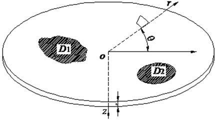
As shown in Fig. 1, D1 and D2 are the pre-stress domain. Stress σ in the circular plate structure can be expressed as:
where:
Is the structural stress; σf=[σf,r,σf,θ,σf,z,τf,rθ,τf,rz,τf,θz]T is the dynamic stress caused by dynamic loading; and σ0=[σ0,r,σ0,θ,σ0,z,τ0,rθ,τ0,rz,τ0,θz]T is a complex pre-stress, in which σ0= 0 indicates no complex pre-stress distribution.
For the thin plate, σz=τrz=τθz= 0, and stress can be expressed as:
If only the radial direction pre-stress σ0,r and circumferential pre-stress direction σ0,θ are considered, then the pre-stress can be expressed as σ0=[σ0,r,σ0,θ,0,0,0,0]T.
3. Differential equations of pre-stressed circular plate
The relationship between structural stress and strain with complex pre-stress distribution for the circular plate structure is examined in this section.
3.1. Force analysis of element body
The forces and moments that act on the element body consist of two parts when the circular plate structure is vibrating, that is, the force and moment caused by the vibration displacement and the coupling force caused by the vibration displacement and pre-stress.
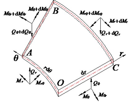
An element body with the size of dr and rdθ is selected, as shown in Fig. 2. Qr and Qθ are the shear force in the element body, and Mr, Mθ, Mθr, and Mrθ are the bending moments in the element body. The polar coordinate system indicates that the shear force and bending moment can be expressed as:
where D=Eh3/12(1-μ2) is the bending strength of the circular plate structure, μ is the Poisson’s ratio, E is the Young’s modulus, and h is the plate thickness.
Fig. 2Section force and moment caused by vibration
3.2. Coupling force analysis
Assume that the complex pre-stress remains constant during structural vibration. Then, curves OA and OC of the original neutral plane are lzOA and lzOC in the course of structural vibration, respectively, and can be expressed as:
Thus, the section area along the curves OA and OC in unit length can be expressed as:
The section area along curves OA and OC remains constant in unit length during structural vibration based on the principle of equal volume according to Eq. (5).
Assume that the pre-stress force remains constant during structural vibration. The section tensile forces N0,r and N0,θ for unit length in directions r and θ also remain constant. If the circular plates are in static equilibrium, then the section tensile forces are parallel to the r and θ axes, and:
Moreover, no force component exists in other directions.
Displacement function w(r,θ,t) exists in the element body; thus, when the element is static, the section tensile force N0,r is no longer parallel to the θ axis, and the angle between the section tensile force N0,r and θ axis is ∂w/∂r. Similarly, section tensile force N0,θ is no longer parallel to the r axis, and the angle between the section tensile force N0,θ and r axis is ∂w/r∂θ, as shown in Fig. 3.
Fig. 3Element body angle
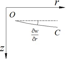
a)
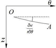
b)
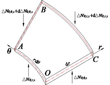
Angles ∂w/∂r and ∂w/r∂θ exists; thus, section tensile force N0,r has a component ΔN0,r,z in the z direction, and section force N0,θ has a component ΔN0,θ,z in the z direction. These force components can be expressed as:
where forces ΔN0,r,z and ΔN0,θ,z are the coupling force between the pre-stress and the vibration displacement, respectively, as shown in Fig. 4.
Pre-stress is constantly perpendicular to the cross section of the element body. The coupling force caused by the pre-stress force and vibration displacement exists in the r and θ directions. Any type of coupling and torques moments does not exist in any direction by the pre-stress vector. The coupling force caused by the pre-stress and vibration displacement in the z direction affects the force balance equation of the element body. The force equilibrium equation in the z direction and the moment equilibrium equations must be established.
Fig. 4Element body coupling force
3.3. Vibration equation of circular plate with complex pre-stress distributions
Coupling forces exist in the circular plate during structural vibration, which is caused by the coupling pre-stress and vibration displacement. The vibration equation should be modified, and the coupling forces must be considered in the equilibrium equations.
(A) Force equilibrium equation in the z direction.
In the element body of the circular plate, two shear forces Qr and Qθ exist, which are caused by the structural vibration in the z direction. Two coupling forces ΔN0,r,z and ΔN0,θ,z are caused by the pre-stress and vibration displacement, respectively. Thus, the force equilibrium equation in the z direction can be expressed as follows:
where ρ is the density of the plate material, and h is the thickness of the plate structure.
(B) Moment equilibrium equations.
No coupling or torque moments are considered in the element body; thus, the body force in the r and θ directions are omitted. The moment equilibrium equations in these directions can be expressed as:
Simultaneously, Eqs. (7) and (8) yield:
The vibration differential equation of the circular plate with complex pre-stress distribution can be expressed as a partial differential equation by substituting Eq. (6) into Eq. (9), as shown as follows:
where ∇2w=∂2w∂r2+1r∂w∂r+1r2∂2w∂θ2; σ0,r and σ0,θ are the complex pre-stresses in the r and θ directions, respectively; ρ is the density of the plate material; and h is the thickness of the plate structure. Eq. (9) can be expressed in a short form as follows:
where:
+1r3(∂∂r-2∂3∂r∂θ2)+1r4(4∂2∂θ2+∂4∂θ4),
are the coupling teams of complex pre-stress and vibration displacement, respectively. The pre-stress values (σ0,r, σ0,θ) are the function of coordinates θ and r. Thus, its partial derivative of spatial coordinates cannot be ignored.
In comparison with the classic motion equation of the circular plate without a complex pre-stress, the coupling item C(w,σ0,r,σ0,θ) is added. In comparison with the motion equation of the circular plate with uniform pre-stress distribution, the varying factor of the pre-stress amplitude is considered. Thus, a new approach is required to gain the analytic solution of Eq. (11). The analytical solution can be applied to the circular plate structure with arbitrarily distributed stress and has a wide range of applications than previous analytical methods.
4. Solution of motion equation
This section discusses the analytical solution of the free vibration problem for the circular thin plate structure.
4.1. Boundary condition
The physical boundary conditions of the circular plate include the free boundary, simply supported boundary, and fixed boundary. The simply supported boundary is discussed in the present work, and it can be expressed as:
4.2. General solution of vibration equation
For the structure of the isotropic material plates, some hypotheses are defined to simplify the calculation; that is, pre-stress σ0,θ is a constant along the circumferential θ direction and pre-stress σ0,r is a function of the design variable r in the rdirection.
The modal decomposition method is applied based on the aforementioned hypotheses, and the mode of the plate may be expressed as a sum of eigenmodes or eigenfunctions. Eq. (11) can be obtained with a form of power series expansion using a Galerkin procedure. The solution of the circular thin plate structure in the polar coordinates system can be expressed as a trigonometric function series as follows:
where ω is the angular frequency, R is the radius of the plate, and Wη is the shape function.
The free vibration equation of the circular plate with complex pre-stress distribution is derived by substituting Eq. (12) into Eq. (10), as shown as follows:
-C(w,σ0,r,σ0,θ)=ω2ρhD∑Nη=0Wηcos(2η-12αr),
where the expression form of complex pre-stresses σ0,r and σ0,θ directly affect the type of analytical solution.
The differential equation can be obtained by multiplying both sides of Eq. (13) by cos(nαr), using the orthogonality of the trigonometric function, and integrating the function from r= 0 to r=R for the circular plate, as shown as follows:
Define K=∫R0C(w,σ0,r,σ0,θ)cos(nαr)dr, where K represents the effect of complex pre-stress. The function K indicates that the structural modes couple together, and a single structural mode can no longer be computed, such that the entire coupling equation must be solved to obtain the coupling modes. Selecting the expressions formed for complex pre-stress is essential; it requires not only to represent the arbitrary pre-stress distribution but also helps to achieve structural mode decoupling. In present work, the trigonometric series, which can satisfy the aforementioned requirements, is selected. The analytical solution of the circular thin plate can be obtained by solving term K.
4.3. Solution of characteristic equation
Eq. (15) is solved based on the different distribution forms of complex pre-stress, and the free vibration characteristic equation is obtained.
4.3.1. Without pre-stress distribution
If the circular thin plate does not have a complex pre-stress distribution (σ0,r=σ0,θ= 0), then the integration term K= 0 and the free vibration characteristic equation of the circular thin plate structure can be expressed as:
Thus, the natural frequency of the circular plate is obtained as:
4.3.2. Uniform pre-stress distribution
If complex pre-stresses σ0,r and σ0,r are constant, then Eq. (15) is translated into a uniform pre-stress distribution problem. Define σ0,r=λ and σ0,θ=τ. Then, the integration term K can be obtained as follows:
Eq. (16) indicates that the pre-stress in the circumferential direction does not affect the characteristic equation. The integration term K can be expressed as K=-hλD(2η-12α)2Wn by using the orthogonality of the trigonometric function. The free vibration equation of the circular plate with uniform pre-stress distribution can be obtained by substituting K into Eq. (14), as shown as follows:
The natural frequency of the circular plate is obtained as:
4.3.3. Complex pre-stress
If the welding residual stress value of σ0,r and σ0,θ varies in one direction, all of them are the function of design variable r. The general principle indicates that the amplitude can be expanded into a trigonometric function series, and the one-dimensional structural pre-stress can be expressed as:
where σr,g and σθ,j are the amplitude of the complex pre-stress in the r direction and θ direction components, respectively; and g and j are positive integers. Substituting Eq. (18) into integration term K yields:
The product-to-sum formula and the orthogonality of the trigonometric function yield:
The integral expressions of the coupling terms of complex pre-stress and vibration displacement can be obtained by substituting Eqs. (20) and (21) into Eq. (19), as shown as follows:
Eq. (22) implies that coupling occurs only among the specified modes. Each mode is coupled with only a few specific modes, rather than with all the other modes. Therefore, for the final vibration equation, the terms that correspond to the specific coupling modes must be calculated. Moreover, after simplification, the calculations do not involve integral operations. Thus, the decoupling of partial modes can reduce the computation cost dramatically without accuracy loss. N equations can be constructed and expressed into a matrix form, as shown as follows:
where X={X1,…,Xn-1,Xn}; Λ is a sparse diagonal matrix that represents the non-stress part; and Ψgj is a sparse non-diagonal matrix. If complex pre-stress exists in the circular plates with Ψ≠ 0, then Λ+Ψ is no longer a spare diagonal matrix. The corresponding free vibration characteristic equation of the circular thin plate structure can be obtained by substituting Eq. (23) into Eq. (17).
4.3.4. Complex pre-stress with series
If the complex pre-stresses σ0,r and σ0,θ are highly complicated, the pre-stress can be expressed in a series as follows:
where σr,g and σr,j are the amplitude of the complex pre-stresses. The method adopted to Eq. (22) indicates that N equations can be established. However, the complex pre-stress influence matrix Ψgj can be expressed as a highly complex form, as shown as follows:
The corresponding free vibration characteristic equation of the circular thin plate structure can be obtained by substituting Eq. (25) into Eq. (14).
4.4. Modal solution
The free vibration characteristic equation of a simply supported circular plate structure is established based on several typical distributions of complex pre-stresses. Although the characteristic equation with complex pre-stress is more complicated than that without pre-stress and uniform pre-stress, it is still a linear equation set, such that the determinant of the characteristic equation coefficient is zero:
The natural frequencies and modes of the circular thin plate with complex pre-stress can be obtained using Eq. (26).
5. Numerical analysis
This section discusses the structural modes and the modal problem of the circular plate structure with complex pre-stress force distribution.
5.1. Model description
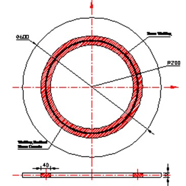
The boundary condition of the circular plate structure is a simply supported boundary, as shown in Fig. 5.
The parameters of the circular thin plate structure are as follows. The radius of the circular plate R is 300 mm, and the plate thickness is 6 mm. The material of the circular plate is steel with the following mechanical performance parameters: density ρ= 7800 kg/m3; modulus of elasticity E= 2.1×10¹¹ N/m3; and Poisson’s ratio μ= 0.3.
In the circular thin plate, a circumferential weld is located at r= 200 mm. The width of the welding stress zone is l= 40 mm. Welding residual stress exists near the seam welding, and welding residual stress is self-balanced in the structure.
Fig. 5Distribution of welding residual stress
5.2. Welding residual stress distribution model
The parameter of the welding residual stress is obtained by simulation analysis using finite element method (FEM) code, Marc. Three types of welding residual stresses are used for comparison. The maximum value of radial residual stress σ0,r is 150 MPa, and that of the circumferential welding residual stress σ0,θ is 250 MPa. In the present study, the variation of the welding residual stress in the thickness direction is neglected for simplicity, and the radial welding residual stress σ0,r is assumed to remain constant along the circumferential direction. The trigonometric function is used to fit the circumferential and radial welding residual stresses, as shown in Fig. 6. The positive and negative values are the tensile and compressive stresses, respectively.
Fig. 6Welding residual stress of circular plate
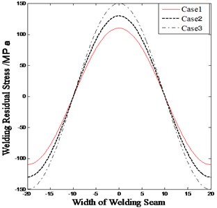
a) Welding residual stress in radial direction
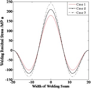
b) Welding residual stress in circumferential direction
5.3. Natural frequencies
The Matlab R2013 is used to analyze the free vibration of the circular plate structure. The influence of welding residual stress on natural frequency are compared, the first ten natural frequencies of the structure are shown in Table 1.
Table 1The first ten natural frequencies under different weld residual stress amplitude
Orders | Natural frequency (Hz) | ||||||
Without welding residual stress | With welding residual stress | ||||||
Case I | Case II | Case III | |||||
Frequency | Difference (%) | Frequency | Difference (%) | Frequency | Difference (%) | ||
1 | 68.3 | 60.3 | –11.71 | 57.2 | –16.25 | 55.6 | –18.59 |
2 | 192.3 | 188.7 | –1.87 | 187.5 | –2.49 | 186.0 | –3.27 |
3 | 192.3 | 188.7 | –1.87 | 187.5 | –2.49 | 186.0 | –3.27 |
4 | 354.2 | 347.3 | –1.95 | 349.3 | –1.38 | 348.5 | –1.61 |
5 | 354.2 | 355.0 | 0.226 | 350.9 | –0.932 | 350.2 | –1.129 |
6 | 411.8 | 410.2 | –0.389 | 409.8 | –0.486 | 409.4 | –0.583 |
7 | 552.4 | 548.4 | –0.724 | 547.2 | –0.941 | 546.6 | –1.05 |
8 | 552.4 | 548.4 | –0.724 | 547.2 | –0.941 | 546.6 | –1.05 |
9 | 672.4 | 667.7 | –0.69899 | 666.2 | –0.92207 | 665.4 | –1.04 |
10 | 672.4 | 667.7 | –0.699 | 666.2 | –0.922 | 665.4 | –1.04 |
Table 1 shows that the amplitude of the weld residual stress has a considerable effect on natural frequency, especially in the first order. The variation magnitude of natural frequencies increases with the pre-stress amplitude. Meanwhile, the relative influence of the welding residual stress decreases with the increase in order. This result can be attributed to the decrease in the overall structural strength of the circular plate caused by the existing pre-stress, particularly near the seam welding.
5.4. Mode shape
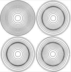
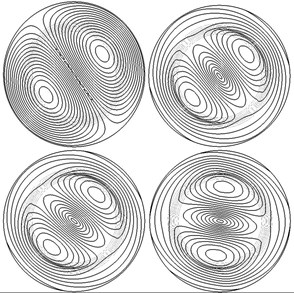
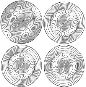
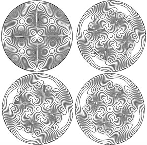
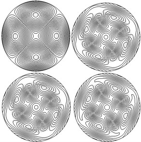
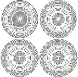
The influence of welding residual stress on the modal is analyzed, and the typical order is compared, as shown in Fig. 7. The structural modal shapes of first to sixth order are compared. The first mode does not have a welding residual stress distribution, and the others have welding residual stresses.
Fig. 7Mode shape in different pre-stress distributions
a) First mode
b) Second mode
c) Third mode
d) Fourth mode
e) Fifth mode
f) Sixth mode
The mode shapes of the circular thin plate changes, particularly in the welding residual stress area, due to the welding residual stress (Fig. 7). The results are as follows. The symmetry characteristic of mode shapes is lost because of the welding residual stress. In the first or sixth order mode shape, some modes of mutation appear in the welding residual stress distribution area. In the second- to fifth-order mode shapes, some modal mutations appear at the center of the circular plate, although the area is far from the seam welding. In the fourth- and fifth-order mode shapes, modal mutations appear periodically in the seam welding; the influence of the welding residual stress on the mode shape increases with the amplitude because the overall structural strength of the circular plate decreases due to the existing pre-stress, particularly near the seam welding.
5.5. Method verification
FEM is used to verify the analytical solution of the proposed method. The accuracy and advantage of the proposed method are validated by comparing its results with the FEM results. The FEM commercial code, Abaqus 2012, is applied to analyze the natural frequency of the circular plate structure. The design parameters are the same for the analytical solution method and FEM. Fig. 8 shows the finite element model.
Fig. 8Finite element model of the circular plate structure
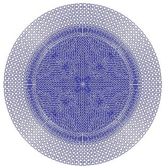
The comparison results of the natural frequencies between the proposed method and FEM are shown in Table 2.
Table 2comparison of the presented method and FEM
Orders | Natural frequency (Hz) | ||||||||
Case I | Case II | Case III | |||||||
Present method | FEM method | Difference (%) | Present method | FEM method | Difference (%) | Present method | FEM method | Difference (%) | |
1 | 60.3 | 59.1 | –1.99 | 57.2 | 56.4 | –1.39 | 55.6 | 54.3 | –2.34 |
2 | 188.7 | 186.2 | –1.32 | 187.5 | 184.2 | –1.76 | 186.0 | 184.5 | –0.81 |
3 | 188.7 | 186.3 | –1.27 | 187.5 | 185.1 | –1.28 | 186.0 | 184.2 | –0.96 |
4 | 347.3 | 348.9 | 0.46 | 349.3 | 352.4 | 0.89 | 348.5 | 355.1 | 1.89 |
5 | 355.0 | 353.6 | –0.39 | 350.9 | 348.5 | –0.68 | 350.2 | 347.1 | –0.88 |
6 | 410.2 | 407.8 | –0.58 | 409.8 | 405.3 | –1.09 | 409.4 | 405.1 | –1.05 |
7 | 548.4 | 550.6 | 0.40 | 547.2 | 552.4 | 0.95 | 546.6 | 549.3 | 0.49 |
8 | 548.4 | 550.8 | 0.44 | 547.2 | 551.3 | 0.75 | 546.6 | 548.9 | 0.42 |
9 | 667.7 | 672.1 | 0.66 | 666.2 | 664.2 | –0.30 | 665.4 | 670.5 | 0.76 |
10 | 667.7 | 672.3 | 0.69 | 666.2 | 664.3 | –0.28 | 665.4 | 670.4 | 0.75 |
Table 2 shows that the results obtained by the proposed method and the FEM agree well, particularly in the high-frequency band, which verifies the validity of the proposed method. Generally, these results show that the proposed method is accurate and that its results are reliable. Form the table, the welding residual stress cannot be fully fitted to the welding residual stress curve in the finite element model due to mesh density, thereby leading to the difference between the theoretical and finite element solutions.
6. Conclusions
The vibration equation with complex pre-stress (welding residual stress) distribution for a circular plate is derived. The analytical solution of the differential equations is obtained by defining the mode shape function, and the influence of welding residual stress on the circular plate structure is compared. The results of this study provide a novel approach for the analysis of the influence of welding residual stress on the structural vibration problem and expands the research domain of complex pre-stress.
References
-
Nie G. J., Zhong Z. Semi-analytical solution for three-dimensional vibration of functionally graded circular plates. Computer Methods in Applied Mechanics and Engineering, Vol. 196, Issues 49-52, 2007, p. 4901-4910.
-
Lee W. M., Chen J. T. Analytical study and numerical experiments of true and spurious eigensolutions of free vibration of circular plates using real-part BIEM. Engineering Analysis with Boundary Element, Vol. 32, Issue 5, 2008, p. 368-387.
-
Wu T. Y., Liu G. R. Free vibration analysis of circular plates with variable thickness by the generalized differential quadrature rule. International Journal of Solids and Structures, Vol. 38, Issue 44, 2001, p. 7967-7980.
-
Wang C. Y. The vibration modes of concentrically supported free circular plates. Journal of Sound and Vibration, Vol. 333, Issues 1-2, 2014, p. 835-847.
-
Haterbouch M., Benamar R. The effects of large vibration amplitudes on the axisymmetric mode shapes and natural frequencies of clamped thin isotropic circular plates. Part I: iterative and explicit analytical solution for non-linear transverse vibrations. Journal of Sound and Vibration, Vol. 265, Issue 1, 2003, p. 123-154.
-
Haterbouch M., Benamar R. The effects of large vibration amplitudes on the axisymmetric mode shapes and natural frequencies of clamped thin isotropic circular plates. Part II: iterative and explicit analytical solution for non-linear coupled transverse and in-plane vibrations. Journal of Sound and Vibration, Vol. 277, Issues 1-2, 2004, p. 1-30.
-
Yalcin H. S., Arikoglu A., Ozkol I. Free vibration analysis of circular plates by differential transformation method. Applied Mathematics and Computation, Vol. 212, Issue 2, 2009, p. 377-386.
-
Bauer H. F., Eidel W. Determination of the lower natural frequencies of circular plate with mixed boundary conditions. Journal of Sound and Vibration, Vol. 292, Issue 3, 2006, p. 742-764.
-
Khan I., Zhang S. Effects of welding-induced residual stress on ultimate strength of plates and stiffened panels. Ships and Offshore Structures, Vol. 6, Issue 4, 2011, p. 297-309.
-
Chen C. S., Fung C. P., Chien R. D. A further study on nonlinear vibration of initially stressed plates. Applied Mathematics and Computation, Vol. 172, Issue 1, 2006, p. 349-367.
-
Ashwear N., Eriksson A. Natural frequencies describe the pre-stress in tensegrity structures. Computers and Structures, Vol. 138, Issue 9, 2014, p. 162-171.
-
Liu Z. Z., Li T. Y., Zhu X., et al. The effect of hydrostatic pressure fields on the dispersion characteristics of fluid-shell coupled system. Journal of Marine Science and Application, Vol. 9, Issue 2, 2010, p. 129-136.
-
Zhang Y. L., Daniel G. G., Jason M. R. Vibration of prestressed thin cylindrical shells conveying fluid. Thin-Walled Structures, Vol. 41, Issue 12, 2003, p. 1103-1127.
-
Kang W., Lee N. H., Pang S. S., et al. Free vibration of polar orthotropic circular plates with elastic growth stresses and drying stresses. Applied Acoustics, Vol. 69, Issue 11, 2008, p. 985-993.
-
Mead D. J. Vibration and buckling of the free-free plates under non-uniform in-plane thermal stresses. Journal of Sound and Vibration, Vol. 260, Issue 1, 2003, p. 141-165.
-
Chen L. Y., Liu Y. Acoustic characteristics analysis of cylindrical shell with prestress in local areas. International Journal of Acoustics and Vibration, Vol. 21, Issue 4, 2016, p. 301-307.
-
Gao Y. Y., Tang G., Wan W. The calculations of natural frequency of quadrate thin plate with welding residual stress. Journal of Vibration and Shock, Vol. 33, Issue 9, 2014, p. 165-177, (in Chinese).
-
Yang N., Chen L. Y., Yi H., et al. A unified solution for vibration analysis of plates with general structural stress distributions. International Journal of Naval Architecture and Ocean Engineering, Vol. 8, Issue 1, 2016, p. 615-630.
About this article
This work is partially supported by the Fund of State Key Laboratory of Ocean Engineering (Grant No. 1507). This support is gratefully acknowledged by the authors.

