Abstract
The proposed research involves, an implementation of solar photovoltaic array and battery powered enhanced dc-dc converter using B4-inverter fed brushless dc motor drive system for agricultural water pumping applications. It consists of step up and step-down converter, DC-link module. DC-link switching is achieved by reduced ripple voltage which results in improved quality of obtained output power. The Three Port Converter has been proposed and operated in unidirectional and/or bidirectional way simultaneously, for achieving an inherent dual voltage and power flow control. Switch count makes the system more cost effective. An excellent tracking performance under dynamic condition with negligible oscillations around optimum operating point is achieved. Optimally selecting the initial value of duty ratio and its perturbation size offer soft starting of BLDC motor by slowly increasing the DC-link voltage of VSI. A simulation model of solar photovoltaic array and battery powered enhanced DC-DC converter is developed and its performance is analysed for various operating conditions.
1. Introduction
1.1. Significance of PV-battery powered brushless DC motor (BLDC) drive system and requirement of dual output converter
Due to dramatic increase in energy consumption for the last decades, recourses and environmental problem are emerging as global, and thus energy reducing technology is one of the greatest issues to be solved. Renewable energy sources and the electric machines, as pollution-free and highly efficient energy conveying devices with low noise characteristic have an important role to solve the problem. Among of renewable sources, photovoltaic (PV) generation is gaining increased importance thanks to inherent advantages like absence of fuel cost, no noise and wear due to absence of moving parts, little maintenance and not producing any green-house gasses [1]. One of the most popular applications of the PV energy utilization is water pumping system driven by an electric motor. In this application due to costs of PV equipment’s and water pumps are expected to decrease more and more over the next few years, it is no wonder that the demand for the PV power becomes widespread. These factors can make PV water pumping systems more economic in the near future. In remote areas PV water pumping system can be used in many applications such as household expenditure, water for irrigation, agriculture purpose, and village water supplies. The advantages of using water pumps powered by PV system include low maintenance, ease of installation and reliability [2].
A three-phase induction motor is widely used in PV array fed water pumping for irrigation and domestic purposes due to its suitability for applications in contaminated and isolated areas, low cost, reliability and low maintenance requirement [3]. A DC motor is also used in [4], but owing to a high maintenance requirement caused by the presence of brushes and commutator, it is not preferred for water pumping. Thus, a high efficiency of a permanent magnet synchronous motor has motivated the researchers to employ this motor where a high power submersible water pumping system is installed [5]. Some attempts in the area of PV array fed water pumping using a synchronous reluctance motor and switched reluctance motor have been made in the literature [6]. However, these motors are not received much attention for PV array fed water pumping till now, probably due to a very high torque ripple and acoustic noise problem associated with this drive [7]. On the other hand, the Brushless DC (BLDC) Motor has many advantages over conventional motors; such as better speed and torque characteristics, high efficiency and reliability, long operation life, noiseless performance, low electromagnetic interference [8], various researchers are focusing on this drive for PV array based water pumping and so opted in this work. A BLDC motor is employed to drive the water pump based on PV array, which manifests its suitability for water pumping. Today, more and more variable speed BLDC drives are designed into pump products to increase product performance and system efficiency. A DC-DC converter is commonly placed between the PV array and B6-Inverter fed BLDC motor pump in order to track the optimum operating point of the PV array using a maximum power point tracking (MPPT) technique [9, 10]. To implement the INC-MPPT algorithm, the direct duty ratio control is adapted in view of the simplicity. This method obviating the proportional-integral (PI) controller, directly uses duty ratio as the control parameter. The direct duty ratio perturbation offers very good stability characteristics and high energy utilization efficiency due to the low impact of noise and the absence of oscillation. Moreover, higher perturbation rates up to the PWM rate can be used without losing the global stability of the system. An excellent tracking performance under dynamic condition with negligible oscillations around optimum operating point is achieved. Optimally selecting the initial value of duty ratio and its perturbation size offer soft starting of BLDC motor by slowly increasing the DC-link voltage of VSI.
Fig. 1Block diagram of PV powered BLDC motor drive system
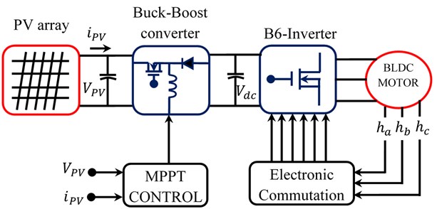
However, in practice, operating point oscillates around the MPP. As the perturbation size reduces, the controller takes more time to track the MPP of SPV array. An intellectual agreement between the tracking time and the perturbation size is held to fulfill the objectives of MPPT and soft starting of BLDC motor. In order to achieve soft starting, the initial value of duty cycle is set as zero. In addition, an optimum value of perturbation size (∆D= 0.001) is selected, which contributes to soft starting and also minimizes oscillations around the MPP. The configuration of the PV array fed BLDC motor is proposed [11] as shown in Fig. 1. A PV array precedes the dc to dc converter which is connected to a B6-Inverter (basic voltage source inverter consists of six switches) feeding the BLDC motor. The operating point of the PV array is tracked by MPPT control and boost converter. An inbuilt encoder on the BLDC motor generates the Hall Effect signals (ha,hb,hc) whichare further decoded to generate the switching pulses for the B6-Inverter by the so called electronic commutation of BLDC motor.
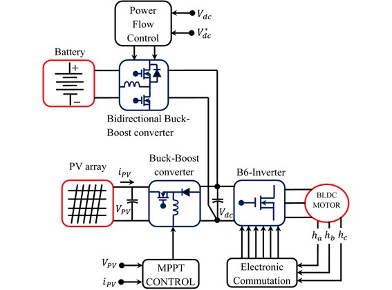
Because of the changing environmental conditions like temperature and solar irradiation, the PV characteristics curve is inconsistent operating point, thus imposing a challenge to the tracking subject. The sudden variation of solar insolation/temperature has led to the reduction in the rated solar power. The dynamics in solar power is directly affects BLDC motor speed, thus the speed control process is not feasible. As a consequence of this recent trend, the focus is on the battery backup powered system in order to satisfy the load (BLDC motor) requirement. PV energy and battery have different voltage levels. So, to provide a specific voltage level for load the individual dc-dc converter is required for maintain appropriate power flow between input sources (PV and Battery) as shown in Fig. 2.
Fig. 2Block diagram of PV and battery powered BLDC motor drive system
The classical B6-Inverterhas to date found many applications in the industry with many topological options available for selection depending on the particular needs and scenarios under consideration. Among the common needs stated by the users, one of which is the ability to implement an inverter using reduced element count so as to lower the overall cost of the system. For achieving that, the B4-Inverter (four switch three phase inverter) is found to be the preferred topology with a number of researchers working on it, as documented in [12, 13]. Comparing with the traditional B6-Inverter using six semiconductor switches, the B4-Inverter uses only four switches and a simpler gating control circuitry with a split dc source needed at its input end. The four switches together form two phase legs for controlling two phases (phases A and B) of an external three-phase load with the third phase (phase C) tied to the split dc source neutral terminal. However, the classical B6-inverter is widely used in many applications while the B4 inverter is rarely used. Because the B4-Inverters are known to have some disadvantages compared to normal B6-Inverters: the voltage utilization factor is halved compared to the B6-Inverter. On the other hand, the capacitor center tap voltage is fluctuating, and it destroys the balance among the motor phase currents [14]. The capacitor center tap voltage fluctuation increases as the load torque becomes higher or the frequency of a B4-Inverterbecomes lower, and the unbalanced motor current leads to an inverter failure and torque pulsation [15]. B4 inverter is best than the B6 inverter are shown in Table 1.
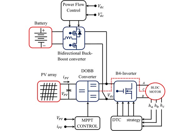
The present study incorporates a DTC strategy which exhibits a capability of reducing the torque ripple during sector to-sector commutations. On the other hand, to mitigate the effects of the capacitor center tap voltage fluctuation, DOBB converter is utilized in-between PV and B4-Inverter as shown in Fig. 3. In this DOBB converter, several and different controlled output voltages can be generated, which may be useful in B4-Inverter fed BLDC motor drives.
Fig. 3 illustrates the newly introduced SIMO topology that can carry out both of the step up and step-down conversions. DOBB converter offers versatility due to its capabilities in improving the output voltage control during the dynamic (sudden variation) in input voltage and load disturbances conditions. Moreover, for applications regarding the load or input voltage disturbance, DOBB converter control possesses the capability to eliminate the impact of these disturbances from the output voltages.
Table 1B4 inverter vs B6 inverter
Sector | Conduction of switches for B6-Inverter | Conduction of switches for B4-Inverter |
0-60 | Q1, Q6 | Q1, Q4 |
60-120 | Q2, Q3 | Q2 |
120-180 | Q3, Q6 | Q4 |
180-240 | Q4, Q5 | Q3 |
240-300 | Q1, Q4 | Q1 |
300-360 | Q2, Q5 | Q2, Q3 |
Total number of switches conduct at 0-360° | 12 | 8 |
Switching losses for 300 Watt system | 2.48 Watt | 1.36 Watt |
Fig. 3Block diagram of PV-battery powered BLDC drive system using proposed converter and B4-inverter
2. Materials and methods
2.1. Architecture and working principle of proposed system
The DOBB converter employed B4-Inverter fed BLDC motor drive system is proposed as shown in Fig. 4. The proposed system includes PV powered DOBB converter, battery powered bidirectional buck-boost converter act as backup supply for BLDC motor operates under demand condition and B4-Inverter fed BLDC motor. The proposed D OBB converter includes buck-boost switch (S1), power sharing switch (S2), two power diodes (D1 and D2), a single buck-boost inductor (L1), intermediate capacitor (C1), and output capacitors (C01 and C02). Likewise, bidirectional buck-boost converter includes buck switch (S3), boost switch (S4) and battery inductor (L2). On the other hand, the rear end B4-inverter includes four switches (Q1 to Q4) and a BLDC motor. A duty of switch (S1) presence in unidirectional DOBB converter is extracting the maximum power from PV panel making use of MPPT algorithm. Because the energy conversion efficiency of PV supplies is low, a proper matching between the PV supplies and the electric load should be considered. Therefore, the coupling between the motor load and the PV module is implemented via a MPPT algorithm to operate the PV system at its maximum output power for any temperature and solar radiation level. The basic perturb and observe (P&O) method tracks the maximum power point (MPP) by repeatedly increasing or decreasing the output voltage at the MPP of the PV module, also the implementation of the method is relatively simple. On the other hand regulation of total output voltage (Vdc=VO1+VO2) todesired value is duty of the power sharing switch (S2) presence in DOBB converter.
Fig. 4Proposed PV-battery powered DOBB converter employed B4-Inverter fed BLDC motor driver
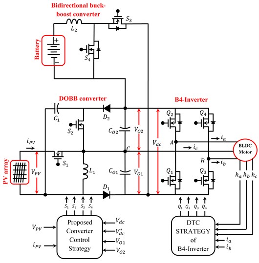
A BLDC motor has three phase windings on the stator and permanent magnets on the rotor. The BLDC motor is also known as an electronically commutated motor because an electronic commutation based on rotor position is used rather than a mechanical commutation which has disadvantages like sparking and wear and tear of brushes and commutator assembly [16]. The proposed work also deals with the direct torque control (DTC) of BLDC motor drives fed by B4-Inverter rather than B6-Inverter in conventional drives. The B4-Inverter could be regarded as a reconfigured topology of the B6-Inverter in case of a switch/leg failure which represents a crucial reliability benefit for many applications especially in electric and hybrid propulsion systems. When partial shading happens in the PV array, battery as energy storage device and a bidirectional DC/DC converter were employed to meet up with the power demand. Among the different arrangements of photovoltaic technology, a stand-alone PV-battery powered backup system can be used in different kinds of applications. A rechargeable battery is generally brought into use in the system for saving energy when the solar energy that is produced exceeds the energy which is required by the load. Here the buck switch (S3) is an active state. The stored energy can be useful for maintaining the system operation during the shading to the PV panel. Therefore, the boost switch (S4) is an active state. Two power switches (S3 and S4) existence in the converter structure are themain controllable elements that control the power flow of the converter.
The chief achievements of this work:
1) The proposed converter is designed to operate in discontinuous conduction for improving the life time of the battery. Also, dual output capability of this converter suitable for B4-inverter thus cost of proposed system considerably reduced.
2) Owing to the single-stage power conversion existing between PV and load ports or between battery and load ports, the power flow of the converter gets highly improved.
3) The proposed converter design along with minimal number of components is introduced for reducing the current conduction losses. Here the DOBB converter is used to track maximum power from PV and provide desired voltage to DC link.
4) On the basis of the three-domain load voltage control method, the load voltage is regulated always with high quality in all power flow situations.
2.2. PV modeling
PV’s are produce electricity in a calm, clean, and consistent manner. A solar cell is basically a p-n junction which is fabricated in a thin wafer of semiconductor. Due to PV effect, the electromagnetic radiation from the sunlight can be directly renewed into electricity. As the sunlight incident on the PV panel, the photons having energy higher than the energy band-gap of the semiconductor substance, extracts some electron-hole pairs equal to irradiation fall [17]. The Fig. 5 describes the PV cell electrical equivalent diode circuit.
Fig. 5Electrical equivalent circuit of the PV cell
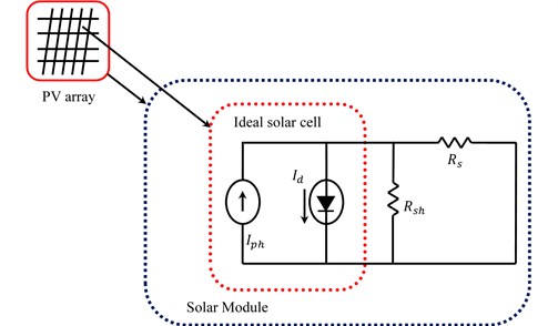
The above electrical circuit includes a cell photo current source (Iph) with intrinsic resistances connected in series and parallel, i.e. (Rsh) and (Rs) respectively as shown in the Fig. 5. Generally, (Rsh) is of comparatively very large value as that of (Rs), consequently ignored to make the analysis simple [18]. PV cells, the fundamental structure of the PV panels, are used widely in all the applications wherever the demand of non-conventional energy is required. Since one half volt generated by a particular cell is insufficient, hence to increase the voltage a number of series connected cells are combined together. Similarly, these cells, connected in series strings are grouped up in parallel in order to raise the current as well. If the circuit has essentially no resistance, the photovoltaic module generates their maximum current. This would produce a short circuit current (Iscr) with a short occurredbetween their negative and positive terminals. Eventuallythe circuit voltage is zero as the module is shorted. The following mathematical Eqs. (1-4) are used to model the PV panel.
Panel photocurrent is given by Eq. (1):
where (ki) represents the temperature co-efficient of short circuit current at (Iscr)=0.0017 A/°C, (T) indicates operating temperature of module in Kelvin, reference temperature (Tr) in Kelvin = 298, (λ) denotes illumination of PV panel in (W/m2) = 1000.
Panel reverse saturation current is given by Eq. (2):
where (q) represents the electronic charge (1.6×10⁻¹⁹ C), (Voc) indicates open circuit voltage of module, sum of series connected cells (Ns), (A) denotes ideality factor, (K) represents Boltzmann constant.
Panel saturation current (I0), which changes with the celloperating temperature, specified by Eq. (3):
where (Eg0) represents the band gap energy for silicon (1.1eV), (B) denotes ideality factor.
The PV module output current which is specified by Eq. (4):
where (VPV) represents the voltage output of the PV panel, (Np) indicates sum of parallel connected cells. Moreover, two different switching frequencies of switches (S1=5 kHz andS2= 10 kHz) are desired to be separate the inductor discharging current as three portions. The top and bottom portion of inductor current iL1, energies the output capacitor (CO2). The middle portions of inductor current iL1, energies the output capacitor (CO1).
2.3. Power flow analysis of PV powered Dobb converter and battery powered bidirectional converter
Depending on the relationship between PV generation power and load demand power, proposed system will work in different power flow modes such as battery charging domain (BCD), PV domain (PVD) and battery discharging domain (BDD). The operation modes in these three domains are analysed below in detail.
2.3.1. Battery charging domain (BCD)
In this mode, PV not only supplies load but also delivers power to battery. This condition occurs when PV power is maximum than the load power, therefore battery must to be charged. In BCD, switches (S1,S2,S3) are active and switch (S4) is entirely OFF. Now the four different operation modes in BCD which is discussed as follows:
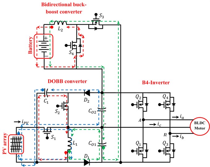
Mode A. In this mode, switch (S2) is turned ON and switches (S1,S3,S4) are turned OFF. Because (S2) is ON, diodes (D1 and D2) are reversely biased. So, the inductor (L1) starts discharging to capacitor (C1), and current (iL1) decreases, whereas the intermediate capacitor (C1) starts charging. Meanwhile the inductor (L2) starts discharging to battery via body diode of switch (S4), and current (iL2) decreases, whereas the battery starts charging. The equivalent circuit of proposed converter operates in this mode, which is shown as red line in Fig. 6.
Mode B. In this mode, switch (S1) is turned ON and switches (S2,S3,S4) are turned OFF. Because (S1)is ON, diode (D2) is forward biased and diode (D1) is reversely biased. So, the inductor (L1) starts charging from PV, and current (iL1) increases. Alternatively the current in capacitor(C1) and PV starts discharging to output capacitor (CO2) via diode (D2), and current (iC1) decreases, whereas the output capacitor current (IO2) increases.The equivalent circuit of proposed converter operates in this mode, which is shown as blue line in Fig. 6.
Mode C. In this mode, switch (S3) is turned ON and switches (S1,S2,S4) are turned OFF. The output capacitors (C01 and C02) are discharged and deliver their stored energy to B4-Inverter fed BLDC motor. Also, the surplus energy available in the output capacitors (CO1 and CO2) are discharged and deliver their stored energy to battery via switch (S3), and current (ibat)increases, whereas the battery starts charging. Meanwhile the diode (D1) is forward biased to create circulating current path of inductor (L1), thus capacitor (CO1) current increases. The equivalent circuit of proposed converter operates in this mode, which is shown as green line in Fig. 6.
Mode D. In this mode, switches (S2 and S3) are turned ON and switches (S1,S4) are turned OFF. The surplus energy available in the output capacitors (CO1 and CO2) are discharged and deliver their stored energy to battery via switch (S3), and current (ibat) increases, whereas the battery starts charging. Meanwhile the inductor (L1) starts discharging to capacitor (C1) via switch (S2), and current (iL1) decreases, whereas the intermediate capacitor current (iC1) increases. The equivalent circuit of proposed converter operates in this mode, which is shown as red and purple line in Fig. 6 respectively. A voltage follower approach is adjustable for controlling the DOBB converter when it operates with DCM. A dual voltage sensors, i.e. total output voltage and capacitor (CO2) voltage measurement sensors, is necessary for regulating output voltage of the DOBB converter. Fig. 6 presents a closed loop control of the DOBB converter. This control strategy comprises a voltage error generator, Output Voltage Controller (OVC), Capacitor Voltage Controller (CVC) and a PWM generator.
Fig. 6Equivalent circuit of proposed converter operates in BCD
2.3.2. PV domain (PVD)
In this mode, PV only supplies loads. This condition occurs when PV power is equal to load power. In PVD, switches (S1,S2) are active and switches (S3 and S4) are entirely OFF. The three different operation modes in PVD which is discussed as follows.
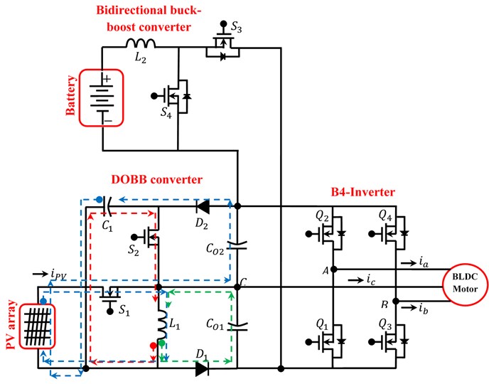
Mode E. In this mode, switch (S2) is turned ON and switches (S1,S3,S4) are turned OFF. Because (S2) is ON, diodes (D1 and D2) are reversely biased. So, the inductor (L1) starts discharging to capacitor (C1), and current (iL1) decreases, whereas the intermediate capacitor current (iC1) increases. The equivalent circuit of proposed converter operates in this mode, which is shown as red line in Fig. 7.
Mode F. In this mode, switch (S1) is turned ON. Because (S1) is ON, diode (D2) is forward biased, so switch (S2) is turned ON/OFF. So, the inductor (L1) starts charging from PV, and current (iL1) increases. Alternatively, the current in capacitor (C1) and PV starts discharging to output capacitor (CO2) via diode (D2), and current (iC1) decreases, whereas the output capacitor current (IO2) increases. The equivalent circuit of proposed converter operates in this mode, which is shown as blue line in Fig. 7.
Mode G. In this state, switches (S1 and S2) are turned OFF. So diode (D1) is forward biased. Hence the inductor (L1) current is completely discharging to output balancing capacitor (CO1) via diode (D1), and current (iL1) decreases, whereas the output capacitor current (IO1) increases. The equivalent circuit of proposed converter operates in this mode, which is shown as green line in Fig. 7.
Fig. 7Equivalent circuit of proposed converter operates in PVD
2.3.3. Battery discharging domain (BDD)
In this mode, two sources PV and battery are responsible for supplying the load. In BDD, switch(S3) is OFF entirely and switch (S1,S2,S4) are active. The five different operation modes in BDD which is discussed as follows:
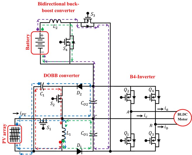
Mode H. In this mode, switch (S2) is turned ON and switches (S1,S3,S4) are turned OFF. Because (S2) is ON, diodes (D1 and D2) are reversely biased. So, the inductor (L1) starts discharging to capacitor (C1), and current (iL1) decreases, whereas the intermediate capacitor (C1) starts charging. The equivalent circuit of proposed converter operates in this mode, which is shown as red line in Fig. 8.
Mode I. In this mode, switch (S1) is turned ON and switches (S2,S3,S4) are turned OFF. Because (S1) is ON, diode (D2) is forward biased and diode (D1) is reversely biased. So, the inductor (L1) starts charging from PV, and current (iL1) increases. Alternatively the current in capacitor (C1) and PV starts discharging to output capacitor (CO2) via diode (D2), and current (iC1) decreases, whereas the output capacitor current (IO2) increases.The equivalent circuit of proposed converter operates in this mode, which is shown as blue line in Fig. 8.
Mode J. In this mode, switches (S1 and S4) are turned ON and switches (S2,S3) are turned OFF. So, the inductor (L1) starts charging from PV, and current (iL1)increases. Alternatively, the current in capacitor (C1) and PV starts discharging to output capacitor (CO2) via diode (D2), and capacitor current (IO2) increases. Meanwhile the additional need of load current is extracted from battery and stored in inductor (L2), therefore inductor (L2) current increases. The equivalent circuit of proposed converter operates in this mode, which is shown as green line in Fig. 8.
Mode K. In this mode, switch (S4) is turned ON and switches (S1,S2,S3) are turned OFF. So the additional need of load current is extracted from battery and stored in inductor (L2), therefore inductor (L2) current increases.Meanwhile the diode (D1) is forward biased to create circulating current path of inductor (L1), thus capacitor (CO1) current increases.The equivalent circuit of proposed converter operates in this mode, which is shown as green line in Fig. 8.
Mode L. In this mode, switches (S1,S2,S3 and S4) are turned OFF. So, the remaining current stored in inductor (L2) is starts discharging to output capacitor (CO1 and CO2) via body diode of switch (S3). Similarly, the diode (D1) is forward biased to create circulating current path of inductor (L1), thus inductor (L1) current decreases. The equivalent circuit of proposed converter operates in this mode, which is shown as purple line in Fig. 8.
Fig. 8Equivalent circuit of proposed converter operates in BDD
2.4. Control strategy of Dobb converter
The control strategy is developed to attain constant voltage and control current storage capability of the topology to enhance the dynamic response of the converter when load or input voltage disturbances are applied.
For the cases of PV current variation or load current drop, which may cause output fluctuation, therefore closed loop control is necessary which senses system actual output voltage and activates the power switches to optimize the power flow of converter topology. Four power switches (S1,S2,S3 and S4) in the converter structure are themain controllable elements that control the power flow and output voltages of the converter. The proposed DOBB converter control strategy as shown in Fig. 9.
The MPPT method makes use of an algorithm and an electronic circuitry. The method is based on the rule of impedance matching between load and PV module, which is compulsory for maximum power transfer. Because the output power of the PV module fluctuates with change in direction of the sun, change in solar insolation level and change in temperature. To enhance the characteristics of the PV module for particular operating condition needs MPPT techniques. By the way, an available MPPT algorithm based on Perturb and Observe (P&O) is used for the system. It introduces an initial perturbation to the DOBB converter voltage by changing the gate signal duty cycle and then observations are made using sensing circuitry to change the gate signal duty cycle to move closer to the MPP. Perturb and Observe uses voltage and current measurements to calculate change in power over a change in time and change in the duty cycle of the signal sent to the gate of the switch (S1) in the DOBB converter as shown in Fig. 9.
Fig. 9Closed loop control of DOBB converter
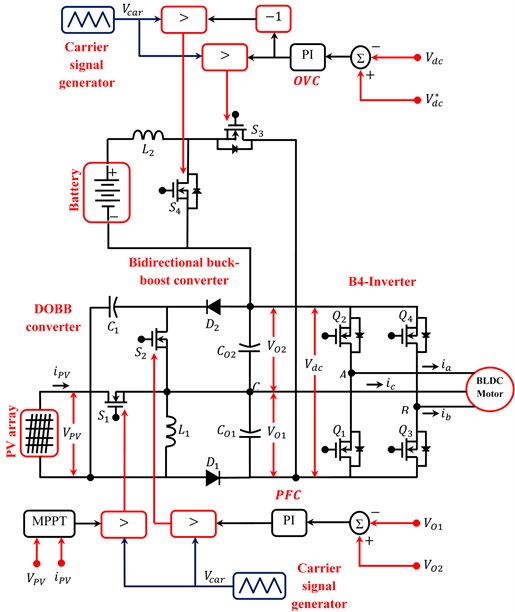
The DOBB converter can increase/decrease the voltage of a low level voltage input power source to a controllable voltage dc bus and mid-level voltage output terminals. The proposed DOBB converter has dual outputs with equal/different voltage levels which make it suitable for interfacing to B4-Inverter employed BLDC motor drive. B4-Inverterwhich is used must be with non-floating dc-links. Now to attain non-floating dc-links, the output voltage (VO1) is compared with output voltage (VO2). After comparing, produced error is processed through output voltage controller (OVC) then processed signal is fed to PWM generator as shown in Fig. 9. By connecting PWM pulse to the switch (S2) of the converter we can get controllable output voltages at output stages.
Similarly, in DOBB converter, the loads power can be flexibly distributed between input sources (PV and battery). Also, charging or discharging action of battery processed by power flow controller (PFC). In BCD, PV not only supplies loads but also delivers power to battery. This situation occurs when load power is low and battery requires to be charged. Therefore, regulation of the battery charging current (iBAT) to desired value is the duty of switch (S3) basis on actual dc-link voltage (Vdc). Similarly, in BDD, PV and battery supplies loads. This situation occurs when load power is high and battery requires to be discharged. Therefore, regulation of the battery discharging current (iBAT) to desired value is the duty of switch (S4) basis on actual dc-link voltage (Vdc) as shown in Fig. 9.
2.5. DTC of B4-inverter fed BLDC motor drive
The operation of the B4-inverter-fed BLDC motor drive is explained by this section. Fig. 10 shows the connections of the drive with two phases (phase-A and phase-B) of the BLDC motor supplied through the B4-Inverter legs, while the third one (phase-C) is linked to the middle point of the dc-bus voltage. Let us call (V1,V2,V3 and V4) the four-active voltage vectors generated by the B4-inverter under the two-phase conduction mode. The corresponding switching combinations (Q1Q2Q3Q4) are equal to (1000), (0010), (0100), and (0001), respectively, where, from left to right, the binary values denote the state of the upper and lower switching signals, corresponding to phase-A and phase-B, respectively. These combinations yield four operating sequences characterized by the conduction of phase-C. The two remaining sequences are characterized by the simultaneous conduction of phase-A and phase-B, and inevitably of phase-C, leading to a three-phase conduction mode. The three-phase conduction mode is characterized by the combinations during which each leg of the B4-inverter has an MOSFET in the on-state, such that: (1001), (1010), (0110), and (0101), with the respective active voltage vectors, noted (U1,U2,U3 and U4).
A DTC strategy executed to these drives in the case of a B4-inverter in the armature. The implementation scheme of such a DTC strategy is shown in Fig. 10. One can notice that the implementation scheme does not include a flux loop, and that the identification of the sectors in the (α-β) plane is achieved considering appropriate combinations of the Hall signals, as given in Table 2.
Table 2Sector identification basis on hall signals
habc | (110) | (010) | (011) | (001) | (101) | (100) |
Sector | I | II | III | IV | V | VI |
Moreover, these signals enable the speed estimation and hence a sensor less control. The speed estimation assumes that the velocity remains constant during a given sector with an opening of (π/3) and is equal to the average one in the previous sector. The resulting algorithm is expressed as following Eq. (5):
where (P) is the pole pair number of the BLDC motor and (∆tk-1) is the time interval spent to cross the previous sector.
The estimation of the electromagnetic torque is based on [19], is expressed as following Eq. (6):
where (bea,beb and bec) are back-EMF normalized functions, obtainedby interpolation and saved in a lookup table.
The actual and desired speed are compared, and the error is given as input to the speed controller and the resulting electromagnetic torque reference is expressed as following Eq. (7):
Fig. 10DTC strategy of B4-inverter
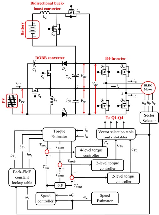
Fig. 11Six sectors limited by the four vectors yielded by the two-phase conduction mode and the larger ones yielded by the three-phase conduction mode
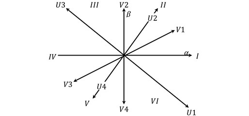
Considering the subdivision of the (α–β) plane in six sectors, as illustrated in Fig. 11, and accounting for the output (CT) of the Four-Levelhysteresis torque controller, the vector selection table can be synthesized considering both anticlockwise and clockwise rotations of the BLDC motor, as given in Table 2.
Referring to Table 3, one can notice that in Sectors II and V, the BLDC motor operates under the three-phase conduction mode. Although these sectors are characterized by the conduction of phase-A and phase-B, there is always a current flowing through phase-C due to its back EMF and its continual connection to the dc-bus. Thus, phase-C behaves as a generator which produces a torque opposite to the ones of phase-A and phase-B. Consequently, their currents turn to be temporarily distorted by undesirable surges in order to generate the required torque. Referring to [20], it has been found that a reduction of the current distortion during Sectors II and V can be gained through an independent control of the torques (Tema) and (Temb) developed by phase-A and phase-B, respectively, instead of the motor overall torque (Tem). To fix, substituting the control combinations adopted in Sectors II and V of Table 2, by the vector selection sub-table given in Table 4, where (CTa) and (CTb) are the outputs of thetwo-level hysteresis controllers of (Tema) and (Temb), respectively.
With this said, the DTC strategy exhibits a capability of reducing the torque ripple during sector-to-sector commutations without any dependence of dc link voltage, phase current, rising and falling times of phase current, and self- inductance.
Table 3Vector selection table of a DTC strategy
CT | +1 | –1 |
Sector I | V2 (0010) | V4 (0001) |
Sector II | U3 (0110) | U1 (1001) |
Sector III | V3 (0100) | V1 (1000) |
Sector IV | V4 (0001) | V2 (0010) |
Sector V | U1 (1001) | U3 (0110) |
Sector VI | V1 (1000) | V3 (0100) |
Table 4Vector selection sub-table to reduce distortion of the BLDC motor phase current in sectors II and V
CTa | +1 | –1 | ||
CTb | +1 | –1 | +1 | –1 |
Sector II | U3 (0110) | U4 (0101) | U2 (1010) | U1 (1001) |
Sector V | U1 (1001) | U2 (1010) | U4 (0101) | U3 (0110) |
3. Results and discussions
In order to verify the performance of the proposed system, simulations have been done in ideal, battery discharging and charging modes by MATLAB software. The simulation parameters of the proposed system are listed in Table 5. Input voltage sources such as PV and battery are considered (VPV=18 V), (Vbat= 24 V). The output voltages of the TPC are desired to be regulated on (VO1=24 V) and (VO2=24 V). Consequently, total output voltage is desired to be regulated on (VT= 48 V). The following parameters such as PV insolation (IRR), PV voltage (VPV), PV current (iPV), PV power (PPV), first output voltage and current of TPC (VO1 and IO1) respectively, second output voltage and current of TPC (VO2 and Io2) respectively, TPC power (Pdc), stator voltage (ea), stator current (ia), rotor speed (N), electromagnetic torque (Te), battery voltage (Vbat), battery current (ibat), battery power (Pbat), and state of charge (SOC%) of the system are measured for validating the proposed idea.
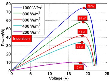
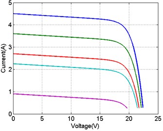
The characteristics of a 75 W PV can be simulated using MATLAB tool based on equivalent circuit model. Important characteristics for a PV consist of output current (iPV) and power (PPV) versus output voltage (VPV). Fig. 12 shows typical (P-V) and (I-V) characteristics of a solar panel under differentinsolation condition and with the consideration of parallel and series resistance obtained by using equivalent model. Also, it is obvious from the Fig. 12; star point shows peak power of each curve, as insolation increases peak power shifted upwards.
The simulation is examined in three different operation modes (i.e. ideal, battery charging and battery discharging) of TPC. In the beginning (i.e. 0 to 0.4 sec), solar insolation of (200 W/m2) is applied on PV, then at 0.4 sec, the solar insolation is increased suddenly from (200 W/m2 to 600 W/m2), also at 0.8 sec, maximum insolation (i.e. 1000 W/m2) is applied on PV as shown in Fig. 13(a). Due to changes in solar insolation, the power generated from PV also varied from (12 W, 42 W and 74 W) respectively, as can be seen Fig. 13(b).
Table 5Specifications of proposed system
S. No | Objects | Values |
75 W PV module specifications at insolation of 1000 W/m2 | ||
1 | Open Circuit Voltage | 22.61 V |
2 | Short circuit current | 4.51 A |
3 | Maximum PV module voltage | 18 V |
4 | Maximum PV module current | 4.17 A |
5 | Maximum PV module power | 75 W |
6 | Solar Cell (Monocrystallin) | 156×156 |
7 | Number of Cells (PCS) | 2×9 |
BLDC motor ratings | ||
8 | Rated power | 39 W |
9 | Rated Torque | 0.125 Nm |
10 | Rated speed | 2800 Rpm |
11 | Rated DC link voltage | 24 V |
Battery specifications | ||
12 | Nominal voltage of battery | 24 V |
13 | Nominal current of battery | 7 Ah |
14 | Nominal power of battery | 168 W/h |
Fig. 12PV characteristics: a) P-V curve, b) I-V curve
a)
b)
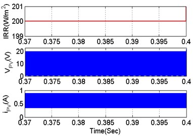
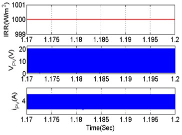
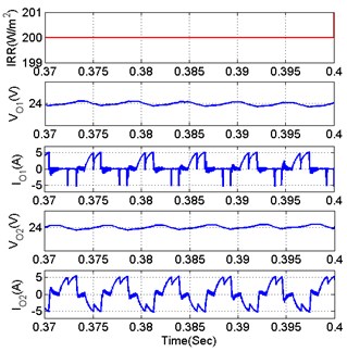
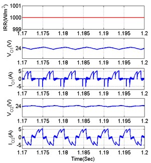
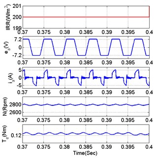
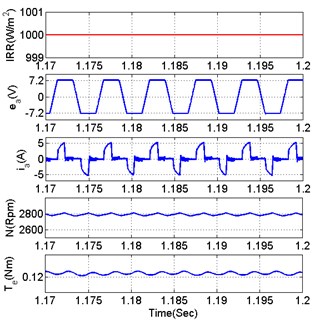
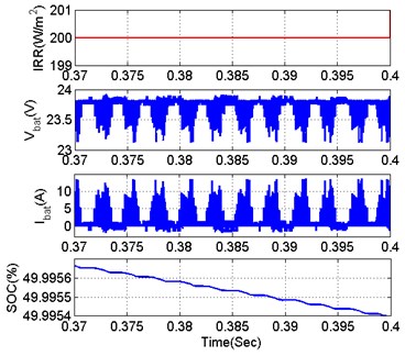
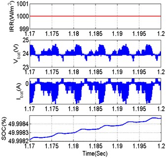
The BLDC motor of power rating 39 W (rotor speed = 2800 Rpm, rated dc link voltage = 24 V, load torque = 0.125 Nm and number of poles = 8) is taken at the load port of the proposed system. The motor delivers 40 W of mechanical power to a load at 2800 Rpm is shown in Fig. 13(c). Also, the rotor speed is maintained at 2800 Rpm as shown in Fig. 13(d) respectively. At low insolation condition (i.e. 200 W/m2), the required load power of 33 W is efficiently extracted from the battery. At a particular instant 23.7 V and +1.38 A is drawn from battery. Similarly, at maximum insolation condition (i.e. 1000 W/m2), the surplus PV power of 28 W is efficiently delivered to the battery. At a particular instant 24.4 V and –1.15 A is applied towards battery respectively, shown in Fig. 13(e). Additionally, at medium insolation condition (i.e. 600 W/m2), the PV solely meet the load requirement, thus battery in ideal condition. As seen from the Fig. 13(e), the negative sign represents that the battery obtains the energy from the PV; consequently, the positive sign indicates that the battery provides energy to the load. The state of charge (SOC) available in battery, at all the three modes is shown in Fig. 13(f). As we observe from Fig. 13, the proposed system is controlled by designed compensators very well. It is worth noting that all converters have specific operating range. Also, power balance between inputs and outputs must be fulfilled. Moreover enlarged operation of proposed system through the PV parameters (VPV,iPV), TPC parameters (VO1,IO1,VO2,IO2), BLDC motor parameters (ea,ia,N,Te) and Battery parameters (Vbat,ibat,SOC%) for the solar insolation of 200 and 1000 W/m2 are demonstrates in detail as shown in Figs. 14-17.
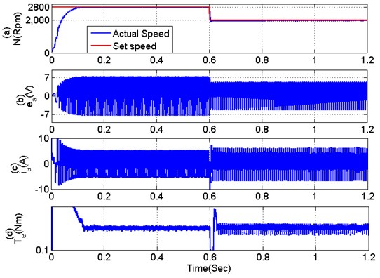
Fig. 18 shows the dynamic performance of the proposed BLDC motor drive during speed control which is obtained by step change in set speed from 2800 to 2000 Rpm. The change in speed is obtained without steady state error as shown in Fig. 18(a). Moreover, a smooth transition and limited overshoot in stator voltage and stator current of the BLDC motor, and then the amplitude and frequency variation of stator voltage and stator current which demonstrates a satisfactory closed-loop performance of the proposed drive as shown in Fig. 18(b) and (c). The applied electromagnetic torque in BLDC motor is shown in Fig. 18(d).
Fig. 13Performance validation of proposed system under different insolation condition
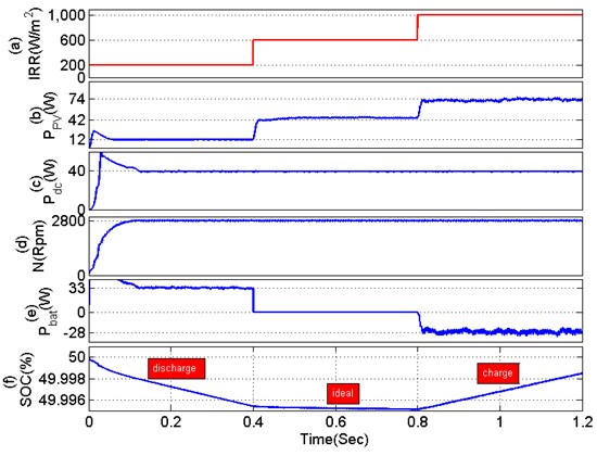
Fig. 14PV parameters under different insolation condition: a) 200 W/m2, b) 1000 W/m2
a)
b)
Fig. 15TPC parameters under different insolation condition: a) 200 W/m2, b) 1000 W/m2
a)
b)
Fig. 16BLDC motor parameters under different insolation condition: a) 200 W/m2, b) 1000 W/m2
a)
b)
Fig. 17Battery parameters under different insolation condition: a) 200 W/m2, b) 1000 W/m2
a)
b)
Fig. 18Dynamic performance validation of proposed system under speed control
3.1. Losses and efficiency analysis of proposed system
The losses in the complete system are classified as losses in various sections such as TPC, B4-Inerter, and the BLDC motor.
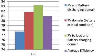
The losses in these three sections are analysed for three different configurations of the proposed system such as battery discharging domain, PV domain and battery charging domain respectively as shown in Fig. 19. From figure it is obvious, the losses in battery charging and battery discharging domain are higher in TPC due to the use of battery employed bidirectional buck-boost converter which increases the switching losses in the system. But PV domain TPC losses are considerably reduced, because in this state battery in ideal condition. The average efficiency achieved in these three cases is 80.95 % as shown in Fig. 20.
Fig. 19Analysis of losses in proposed system under three different domains
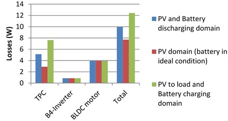
Fig. 20Analysis of efficiency in proposed system under three different domains
4. Conclusions
The TPC and B4-Inverter fed BLDC motor drive has been proposed targeting low/medium power applications. A new method of torque control has been utilized by controlling torque ripple during sector to sector commutations of BLDC motor. The TPC has been operated in unidirectional and/or bidirectional way simultaneously, for achieving an inherent dual voltage and power flow control. A satisfactory closed loop performance has been achieved for speed control of BLDC motor without steady state error. Moreover, Losses and efficiency of the proposed system are analysed with three different domains effectively.
References
-
Mozafari Niapoor S. A. K., Danyali S., Sharifian M. B. B. PV power system based MPPT Z-source inverter to supply a sensorless BLDC motor. IEEE Power Electronics and Drives System and Technologies Conference, 2010, p. 111-116.
-
Gopal C., Mohanraj M., Chandramohan P., Chandrasekar P. Renewable energy source water pumping systems – a literature review. Renewable and Sustainable Energy Reviews, Vol. 25, 2013, p. 351-370.
-
Mapurunga Caracas J. V., De Carvalhofarias G., Moreira Teixeira L. F., De Souza Ribeiro L. A. Implementation of a high-efficiency, high-lifetime, and low-cost converter for an autonomous photovoltaic water pumping system. IEEE Transactions on Industry Applications, Vol. 50, Issue 1, 2014, p. 631-641.
-
Boutelhig A., Bakelli Y., Hadj Mahammed I., Hadj Arab A. Performances study of different PV powered DC pump configurations for an optimum energy rating at different heads under the outdoor conditions of a desert area. Energy Journal, Vol. 39, Issue 1, 2012, p. 33-39.
-
Henneberger S., Van Haute S., Hameyer K., Belmans R. Submersible installed permanent magnet synchronous motor for a photovoltaic pump system. IEEE International Electric Machines and Drives Conference Record, 1997.
-
Nabil M., Allam S. M., Rashad E. M. Performance improvement of a photovoltaic pumping system using a synchronous reluctance motor. Electric Power Components and Systems, Vol. 41, Issue 4, 2013, p. 447-464.
-
Domijan A., Buchh T. A. photovoltaic array driven adjustable speed heat pump and power system scheme for a lunar based habitat. IEEE Transactions of Energy Converters, Vol. 13, Issue 4, 1998, p. 366-372.
-
Shao J. An improved micro-controller sensorless based BLDC motor drive for automotive applications. IEEE Transactions of Industrial Applications, Vol. 42, Issue 5, 2006, p. 1216-1221.
-
Subudhi B., Pradhan R. A comparative study on maximum power point tracking techniques for photovoltaic power systems. IEEE Transactions on Sustainable Energy, Vol. 4, Issue 1, 2013, p. 89-98.
-
Kok Soon Tey, Mekhilef S. Modified incremental conductance algorithm for photovoltaic system under partial shading conditions and load variation. IEEE Transactions on Industrial Electronics, Vol. 61, Issue 10, 2014, p. 5384-5392.
-
Rajan Kumar, Bhim Singh, Ambrish Chandra, Kamal Al Haddad Solar PV array fed water pumping using brushless DC motor drive with boost-buck converter. Energy Conversion Congress and Exposition, 2015.
-
Van Der Broeck H. W., Van Wyk J. D. A comparative investigation of a three-phase induction machine drive with a component minimized voltage-fed inverter under different control options. IEEE Transactions on Industry Applications, Vol. IA-20, 1984, p. 309-320.
-
Blaabjerg F., Freysson S., Hansen H. H., Hansen S. A new optimized space-vector modulation strategy for a component-minimized voltage source inverter. IEEE Power Electron. Transactions, Vol. 12, 1997, p. 704-714.
-
Blaabjerg F., Neacsu D. O., Pedersen J. K. Adaptive SVM to compensate DC-Link voltage ripple for four-switch three-phase voltage-source inverters. IEEE Transactions of Power Electronics, Vol. 14, Issue 4, 1999, p. 743-752.
-
Kim J., Hong J., Nam K. A current distortion compensation scheme for four-switch inverters. IEEE Transactions of Power Electronics, Vol. 24, Issues 3-4, 2009, p. 1032-1040.
-
Pillay P., Krishnan R. Modeling of permanent magnet motor drives. IEEE Transactions on Industrial Electronics, Vol. 35, Issue 4, 1988, p. 537-541.
-
Bose Bimal K., Szczesny Paul M., Steigerwald Robert L. Microcomputer control of a residential photovoltaic power conditioning system. IEEE Transactions on Industry Applications, Vol. IA-21, Issue 5, 1985, p. 1182-1191.
-
Nema S., Nema R. K., Agnihotri G. Matlab/Simulink based study of photovoltaic cells/modules/array and their experimental verification. International Journal of Energy and Environment, Vol. 487, Issue 500, 2010, p. 1-3.
-
Taheri A., Rahmati A., Kaboli S. Efficiency improvement in DTC of six-phase induction machine by adaptive gradient descent of flux. IEEE Transactions of Power Electronics, Vol. 27, Issue 3, 2012, p. 1552-1562.
-
Ozturk S. B., Alexander W. C., Toliyat H. A. Direct torque control of four-switch brushless DC motor with non-sinusoidal back EMF. IEEE Transactions of Power Electronics, Vol. 25, Issue 2, 2010, p. 263-271.

