Abstract
Dynamics of deep-hole drilling shaft system is closely related to hole processing quality. From the viewpoint of rotor dynamics and fluid-structure interaction, the governing equation of the drilling shaft system for lateral vibration is obtained taking into account of fluid-structure interaction, rotational inertia, gyroscopic effect, the effect of motion constraints and frictional damping generated by surrounding fluid. The influence of rotational angular velocity and compressive axial force on transient vibration of drilling shaft is mainly examined. It has been found that rotational angular velocity has an obvious effect on the lateral vibration of drilling shaft, whereas the lateral vibration of drilling shaft does not change significantly with the increase of compressive axial force.
1. Introduction
The boring trepanning association (BTA) deep-hole drilling shaft system is a complex system. The dynamic behavior of drilling shaft exerts an unfavorable influence on cutting quality [1-3]. Kong [4] constructed the dynamic model to investigate nonlinear dynamic responses taking into account of the influence of cutting force fluctuation, auxiliary support and mass eccentricity. Perng [5] analyzed the eigenproperties of spinning deep-hole drilling shaft containing flowing fluid and subject to compressive axial force. Al-Wedyan [6] considered the interaction between the workpiece and drilling shaft to investigate whirling vibration of deep-hole drilling shaft. Kenichiro [7] investigated chatter vibration considering support position of drilling shaft in detail.
In this paper, the governing equation is obtained taking into account of fluid-structure interaction, rotational inertia and gyroscopic effect. The influence of rotational angular velocity and compressive axial force on vibration is mainly examined.
2. The equation of motion
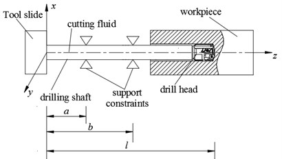
As shown in Fig. 1, the drilling shaft rotating at angular velocity and conveying cutting fluid with flow velocity is subjected to torque on drill head, compressive axial force on drill head and support constraints. The drilling shaft is modeled as a Rayleigh beam which is clamping at one end and hinging at the other end. The equations of motion [6-8] are given by:
where , is density of cutting fluid and drilling shaft; , is internal and external diameter of drilling shaft; , is cross sectional area of drilling shaft wall and bore; , is moment of inertia of drilling shaft and bore; is compressive axial force; is torque; , and , are support stiffness and damping. , is transverse displacement.
Fig. 1Schematic diagram of deep-hole drilling system
The dimensionless quantities are introduced as follows:
and the equation is rearranged as:
3. Method of solution
The Eqs. (9) and (10) are discretized using Galerkin method. The displacement at any point can be expressed as:
where and represents the unknown time-dependent generalized coordinates and and is the corresponding orthogonal eigenfunction of the beam, given by:
where and are the solution of Eqs. (9) and (10).
Substituting Eqs. (5) and (6) into Eqs. (3) and (4), multiplying both sides of Eqs. (3) and (4) by the th eigenfuction and integrating from 0 to 1, Eqs. (3) and (4) can be rewritten as:
where:
and the elements of through are shown as follows:
To solve it simply, the state vector is introduced as follows:
Thus, Eqs. (11) and (12) are transformed into its first-order form:
where:
The matrix is the identity matrix.
4. Numerical results and discussion
The parameters of the drilling shaft system are listed in Table 1. In the study, letting the dimensionless quantity 0.5, 1.5, 7.32×10², 3.81×10², 9.21×10⁴, 4.80×10⁴, 0.05, 0.4 and 0.8, respectively.
Table 1The parameters of the drilling shaft system
Density of drilling shaft (kg/m3) | Density of cutting fluid (kg/m3) | Internal diameter (mm) | External diameter (mm) | Length (m) |
7.8×10³ | 0.865×10³ | 20 | 26 | 5 |
4.1. Effect of rotational angular velocity on vibration
There is some fluctuation in the amplitude of lateral vibration displacement of drilling shaft in Fig. 2(a), 3(a) and 4(a). However, with the passage of time, the overall trend is decreasing. Eventually, the motion of drilling shaft is stable with equal amplitude vibration.
Fig. 2Lateral vibration displacement and radial displacement trajectory
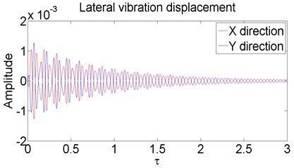
a) ( 10, 10)
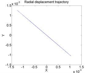
b) ( 10, 10)
By comparing Fig. 2(b), 3(b) and 4(b), the radial displacement trajectory changes from linear to explosive trajectory, which shows that the movement of the drilling shaft is out of control. This will seriously affect the processing quality of the hole.
Fig. 3Lateral vibration displacement and radial displacement trajectory
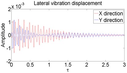
a) ( 50, 10)
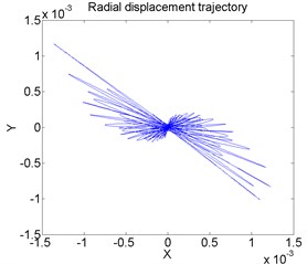
b) ( 50, 10)
Fig. 4Lateral vibration displacement and radial displacement trajectory
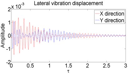
a) ( 100, 10)
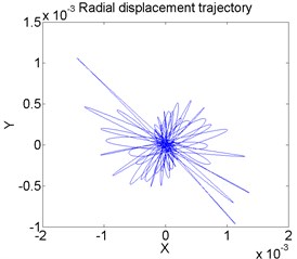
b) ( 100, 10)
4.2. Effect of axial compressive force on vibration
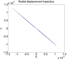
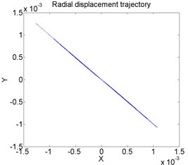
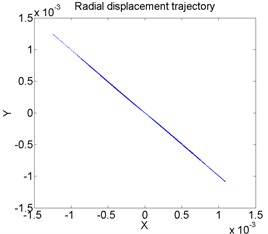
With the increase of axial compressive force, there is no obvious change in radial displacement trajectory of drilling shaft, as shown in Fig. 5. In a certain range, axial compressive force has little effect on the lateral vibration of drilling shaft.
Fig. 5Radial displacement trajectory of drilling shaft for different levels of axial compressive force Ω= 50: a) Γ= 5, b) Γ= 10, c) Γ= 15
a)
b)
c)
5. Conclusions
A systematic mathematical model for drilling shaft system is established. The results indicate that lateral vibration of drilling shaft is becoming more and more fierce with the increase of rotational angular velocity and does not change significantly with the increase of axial compressive force.
References
-
Raabe N. Dynamic Disturbances in BTA Deep-Hole Drilling: Modelling Chatter and Spiraling as Regenerative of the Effects. Advances in Data Analysis, Data Handling and Business Intelligence. Studies in Classification, Data Analysis, and Knowledge Organization, Springer, Berlin, Heidelberg, 2009, p. 745-754.
-
Maleki M. I., Nouri M., Madoliat R. Investigating chatter vibration in deep drilling, including process damping and the gyroscopic effect. International Journal of Machine Tools and Manufacture, Vol. 49, Issues 12-13, 2009, p. 939-946.
-
Philip B., Lamar V., Michael T. Low-frequency regenerative vibration and formation of lobed holes in drilling. Journal of Manufacturing Science and Engineering Transactions of the ASME, Vol. 124, Issue 2, 2002, p. 275-285.
-
Kong L. F., Li Y., Zhao Z. Y. Numerical investigating nonlinear dynamic responses to rotating deep-hole drilling shaft with multi-span intermediate supports. International Journal of Non-Linear Mechanics, Vol. 55, 2013, p. 170-179.
-
Perng Y. L., Chin J. H. Theoretical and experimental investigations on the spinning BTA deep-hole drill shafts containing fluids and subject to axial forces. International Journal of Mechanical Sciences, Vol. 41, Issue 11, 2001, p. 1301-1322.
-
Al Wedyan H.-M., Bhat R. B., Demirli K. Whirling vibrations in boring trepanning association deep hole boring process: analytical and experimental investigations. Journal of Manufacturing Science and Engineering-Transactions of the ASME, Vol. 129, Issue 1, 2007, p. 48-62.
-
Matsuzaki K., Ryu T., Sueoka A. Theoretical and experimental study on rifling mark generating phenomena in BTA deep hole drilling process. International Journal of Machine Tools and Manufacture, Vol. 88, 2015, p. 194-205.
-
Raffa F. A., Vatta F. Gyroscopic effects analysis in the Lagrangian formulation of rotating beams. Meccanica, Vol. 34, 1999, p. 357-366.
About this article
This work was financially supported by the National Natural Science Foundation of China (51175482).
