Abstract
According to the special working environment of drilling proposed design parameters of distance sleeve; The Ansoft Maxwell software is used to optimize the magnetic coupling, and the optimized design process is illustrated with an example; The torque is studied under different rotation angles; The effects of magnetic steel thickness, magnet thickness and magnetic pole number on torque are studied respectively; With the development of the rare earth permanent magnet material, it is imperative to apply the no leakage magnetic coupling to petroleum drilling.
1. Introduction
Measurement while drilling is the basis for oil drilling to realize intellectualization, informatization and automation. It is the abbreviation of underground information real-time measurement and upload technology during drilling [1]. Currently, information transmission is the bottleneck of measurement while drilling technology, including four information transmission modes of electromagnetic wave, intelligent drill pipe, drilling fluid pressure pulse and acoustic wave, wherein drilling fluid pressure pulse further includes three modes of positive and negative pulse as well as continuous wave. Compared with other information transmission modes in measurement while drilling, drilling fluid continuous wave has the advantages of high transmission rate, low cost, high safety and reliability, etc. It is the preferred way of underground information transmission.
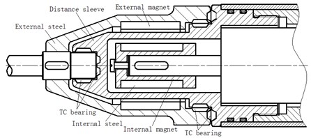
Drilling fluid continuous wave is generated by a continuous wave signal generator. In continuous wave signal generator system, rotary valve is a flow passage component, which is exposed to rapid flow drilling fluid. The drive parts, such as motor, speed reducer, etc., are sealed in a cavity so that the rotation dynamic seal between the rotor shaft and the body is a weak link of the system. Since the rubber seals in two traditional rotating sealing methods of packing seal and mechanical seal are worn easily in downhole environment with high temperature, high pressure, especially vibration make the rubber parts shorten the service life. Because there is shock up to 1000 G 1 ms half sine wave and vibration as high as 20G rms with 5-1000 Hz, thereby leading to drilling failure, increasing the drilling cost, and prolonging the drilling cycle. Tc bearing for drilling tools is combined with magnetic coupling (Fig. 1) for completely solving existing problem in the traditional rotating seal mode on the basis of downhole harsh environmental conditions.
Fig. 1Structural diagram of continuous wave pulse generator magnetic coupling
2. Design of magnetic coupling
2.1. structure and transmission principle of magnetic coupling
The magnetic coupling for the continuous wave signal generator is coaxial as shown in Fig. 1. It is mainly composed of three parts: one is the inner magnetic rotor formed by inner magnetic steel and inner magnet; the second part is external magnetic rotor connected with the rotary valve to form the driven part; The third part is the distance sleeve.
Fig. 2Permanent magnet stagger arrangement and stress diagram
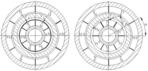
When the inner magnetic rotor is static, magnetic poles are attracted mutually due to isomerism (left of Fig. 2), the magnetic force acted by inner magnetic rotor on external magnetic rotor is radial without tangential component force, and torque is not generated as a result. When the inner magnetic rotor is rotated under the drive of the motor, external magnetic rotor is still in the stationary state due to the role of load inertia and load resistance at the beginning, there is an included angle between inner magnetic rotor magnet center line and the external magnetic rotor magnet center line, which is called corner . When the corner is increased to the torque generated by coupling magnetic filed and equal to the resistance torque, the external magnetic rotor starts to rotate synchronously with the inner magnetic rotor.
2.2. Design and calculation of magnetic coupling distance sleeve
The function of distance sleeve is shown as follows: the internal and external magnetic rotors are separated, and the drive part is sealed in a sealed cavity. Firstly, its stiffness determines the pressure difference value inside and outside the cavity. Secondly, it is converted into the heat, and the temperature in the sealed cavity is improved. The downhole tools are characterized by severe working environment and low radial dimension. It should be designed from the following aspects.
2.2.1. Calculation of distance sleeve wall thickness
The characteristics of high pressure and low radial dimension determine that the magnetic coupling wall is thick, and the wall thickness is calculated according to the following formula [2-3]:
In the formula, – pressure difference of interior and exterior cavities, MPa; – inner diameter of distance sleeve, mm; – permissible stress, MPa, ; – ultimate strength, MPa; – safety coefficient, 3.5-5.
2.2.2. Calculation of distance sleeve radial deformation
Downhole tools have narrow radial space. The radial clearance between the distance sleeve and the internal and external magnetic rotor is very small. the distance sleeve radial deformation calculation formula is shown as follows [3]:
In the formula, – distance sleeve radial displacement, mm; – elasticity modulus, MPa; – Poisson's ratio.
3. Optimization design with Maxwell software
Magnetic coupling has the most important role of realizing torque transmission between the drive part and the driven part. Torque is an important parameter for designing magnetic coupling. Torque transmission is completed through working air gap (total name of distance sleeve and gaps at both sides) magnetic filled, internal and external magnetic rotors of co-axial magnetic coupling are composed of tile-shaped permanent magnet with alternate magnetic poles. must be an even number in order to ensure that all main magnetic flows can form a closed loop circuit [4]. The magnetic filed in the center of the working air gap is formed by magnetic filled intensities of two internal and external corresponding magnets with very complicated distribution. Maxwell finite element software is utilized for simulation to improve the design accuracy and rationality, thereby shortening the design cycle. The design plan can be more concrete and profound.
3.1. Calculating examples
Currently, the magnetic coupling for 6-inch 6 drill collar continuous wave signal generator is adopted as an example for illustrating the design optimization process. Magnetic coupling parameters are shown as follows: 80 MPa, 21 mm, 374 MPa, 2.1×10⁵ MPa, 0.27, inner magnetic steel external diameter is 10 mm, and outer magnetic steel external diameter is 79 mm.
3.1.1. Influence of corner on torque
The torque generated by magnetic coupling coupling magnetic filled is related to permanent magnet performance, physical dimension and many other factors. In addition, it is also related to internal and external magnetic rotor corner (right of Fig. 2). When the 30°, the torque is the maximum aiming at magnetic couplings with 6 poles, the maximum torque represents the upper limit of actually transmitted torque during operation of the magnetic coupling. Table 1 shows the torque value of several groups of corners for calculation.
Table 1Torque of different corners
Corner° | 0 | 5 | 10 | 15 | 20 | 25 | 30 |
Torque N.m / m | 0 | 93 | 175 | 238 | 283 | 309 | 317 |
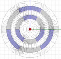
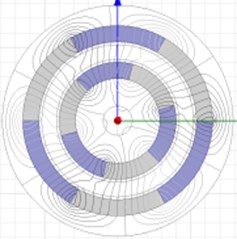
The figure shows that magnetic force line is gradually ‘skewed’ with corner increase, skew is more severe, magnetic filled distribution is more uneven and the transmitted torque is larger. When 30°, magnetic force line is skewed most severely. The radial component of the internal and external magnetic pole acting force is the maximum; therefore, the torque acted on the external magnetic rotor is the maximum.
3.1.2. Influence of magnetic steel on torque
The influence is explained according to magnetic circuit theory. Magnetic steel is equivalent to the conductor in the magnetic circuit, permanent magnet is the power supply, working air gap is the resistance [2], and it can improve the utilization rate of the magnetic materials. Internal and external magnetic steel not only can prevent interference and influence of external magnetic filled, but also can lead the distribution of magnetic force s in the magnetic filled, and adjust leakage flux. Table 2 shows the torque of several different magnetic steel thicknesses.
Fig. 3Distribution drawing of magnetic force lines at different corners
a) 0°
b) 15°
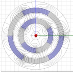
c) 30°
Table 2Relationship between magnetic steel thickness and torque
Magnetic steel thickness mm | 4.5 | 5.5 | 6.5 | 9.5 |
Torque N.m/m | 315 | 315 | 316 | 316 |
Magnetic steel thickness has low influence on torque. However, when the magnetic steel is too thin, and no magnetic saturation appears in the magnetic steel, the magnetic resistance is increased, air gap flux density is reduced, and the torque increment is decreased as a result. When the magnetic steel is too thick, the rotational inertia of rotating parts is larger, thereby increasing the starting torque of the whole system and the instability of the moving parts is increased.
3.1.3. Influence of magnet thickness on torque
Permanent magnet provides magnetic potential in the magnetic circuit. It is clear that the magnetism of the magnetic materials is higher, the magnetic density in the air gap is larger, and the generated torque is larger. When the materials are the same, magnet thickness also affects torque, Table 3 and Table 4 show the torque of several groups of different magnet thicknesses.
Table 3The relationship with the torque when the internal and external magnet thicknesses are the same
Magnet thickness mm | 5.5 | 6.5 | 7.5 | 8.5 | 9.5 | 10 |
Torque N.m/m | 317 | 361 | 395 | 422 | 442 | 451 |
Table 4The relationship with the torque when the internal and external magnet thicknesses are different
Internal magnet thickness mm | 5.5 | 5.5 | 8.5 |
External magnet thickness mm | 6.5 | 7.5 | 5.5 |
Torque N.m/m | 249 | 376 | 334 |
Table 3 shows that when the internal and external magnets have the same thickness, torque is increased with the increase of magnet thickness. When the permanent magnet is increased to certain value, the torque increase is decelerated because after the magnet thickness reaches certain value, magnetic saturation appeared in the magnetic steel, the magnetic resistance is increased, air gap flux density is reduced, and the torque increment is decreased as a result.
Table 4 shows that when the internal and external magnet thicknesses are different, though the torque is also increased with the magnet thickness increase; the torque value is smaller compared with that with the same magnet thickness because magnetic potentials of internal and external magnets are not matched, and the leakage flux is increased.
3.1.4. Influence of magnetic pole quantity no torque
In the design of the magnetic circuit, magnetic pole quantity is an important design parameter. According to the magnetostatic energy expression, it is known that when the N and S poles are changed once, magnetostatic energy storage is increased once, therefore more magnetic poles are beneficial for magnetostatic energy storage, magnetostatic energy is finally converted into kinetic energy, which is released.
Table 5Relationship between magnetic pole quantity and torque
Magnetic pole quantity | 4 | 6 | 8 | 10 |
Torque N.m/m | 375 | 395 | 350 | 286 |
4. Conclusions
Drilling operators utilize modern science and technology and try to increase the oil drainage area greatly, improve sweep efficiency, delay water invasion or gas invasion through drilling complex wells in order to solve the problem of more and more prominent oil supply and demand gap, thereby ultimately improving the oil well production and recovery efficiency of oil and gas. Many spiry drilling tools with rotary dynamic seal are utilized as a result. Magnetism is better and better with further development of rare earth permanent magnet materials. The residual magnetism and magnetic energy product are high. The high performance with high Curie temperature is constantly emerging. Therefore, the torque and volume ratio is more and more larger. The temperature applicable scope is wider and wider. The full-seal magnetic coupling with strong vibration resistance will be widely applied in oil drilling.
References
-
Inglis T. A. Directional Drilling. Petroleum Industry Press, Beijing, 1995.
-
Zhao Kezhong Theory and Design of Magnetic Coupling Transmission. Chemical Industry Press, Beijing, 2009.
-
Li Changxi, Qiao Shi Hydraulic Transmission of Mining Machinery. China Coal Industry Publishing House, Beijing, 1995.
-
Chen Zhigang Magnetic circuit design of magnetic coupling and its application. Journal of Jiangsu University of Science and Technology, Vol. 17, Issue 1, 1996, p. 64-70.
About this article
The paper was supported by the special subject “Directional Rotary Geological Guidance System Development” of China National Petroleum Corporation Major Project (2013E-3801).
