Abstract
In conventional seismic design codes of building structures severe structural damage due to large earthquakes is accepted, provided that the structure does not collapse, and life safety of the residents is guaranteed. The extent of this allowed damage can be so high that after earthquake, demolition and reconstruction of the building becomes inevitable, particularly in near-fault areas. The idea followed in this study is to relocate the damage to some predetermined fuse elements, other than the main structural members, so that the building could be quickly and easily repaired, even after major earthquakes. For this purpose, dividing the building’s structure into two inner and outer parts with different dynamic characteristics, and creating dynamic interaction between them by using yielding plate or hysteretic dampers was investigated. At first, a 5-storey building model was developed and divided into two interactive parts using hysteretic dampers at roof level, and it was tried, by developing a code in MATLAB environment for solving the nonlinear equations of motion, to find the optimal values of the initial stiffness and the yielding strength of dampers, assuming their behavior to be elastic-perfectly plastic. The results of nonlinear time history analyses (NLTHA), by using a set of selected earthquakes accelerograms, showed that by using appropriate initial stiffness and yield strength, the inert-story drifts of both inner and outer structures can be significantly reduced. Then, 5-, 8- and 11-story steel braced buildings were designed by ETABS, and were divided into inner and outer substructures, and then were modeled in PERFORM-3D software using hysteretic dampers with optimal stiffness and strength, obtained from the MATLAB program, and the seismic responses were compared. Final results of the NLTHA show that the inter-story drift values of outer and inner substructures decreases in average by 20 % and 65 %, respectively, comparing to the original structure. This drift reduction leads to decrease of the damage indices of outer and inner substructures by almost 20 % and 80 %, respectively, comparing to the original structure, making it possible in most cases to have an easily repairable structure.
1. Introduction
Most of the structural seismic design standards, in spite of requiring the collapse prevention (CP) performance level (PL), implicitly allow some unacceptable consequences to occur in case of a major earthquake, particularly in populated cities, located in the near-fault seismic areas. These adverse consequences include: 1) the necessity of evacuating and sheltering thousands, even hundreds of thousands of people who have lost their living or working spaces; 2) the need to demolish severely damaged (but not collapsed) buildings, which is very difficult, because of the considered ductility in design, based on the standards, which leads to creation of a large number of plastic hinges in beams and columns, causing large deformation of the building without complete failure; 3) the necessity of removing the debris of the demolished buildings, weighing over millions of tons; and requires thousands of trucks and a very vase suitable place for disposal, and 4) plenty of time and cost as well as enormous skillful human forces needed for the reconstruction of the new buildings to replace the demolished ones. Regarding the above facts, it is much desired that the buildings are designed and constructed in such a way that they can be easily and quickly repaired, even after major earthquakes. One way for achieving the repairable buildings is dividing the skeleton of the building in plan into two or more dynamically interactive parts. If the dynamic characteristics (periods and mode shapes) of the interacting parts are quite different the amount of their seismic interaction can be increased through using some energy dissipation devices or dampers, leading to absorption of the majority of the earthquake input energy in dampers or structural fuses, and therefore the amount of damage to the main structural members becomes minimal.
Interaction between different parts of a building's structures is basically very similar to the interaction between adjacent buildings. In recent decades some researchers have worked on the interaction of adjacent or coupled buildings. Bhaskararao and Jangid investigated the seismic response of the adjacent buildings having the damper interface element. They mentioned that connection of the adjacent buildings not only would reduce the seismic response of the structures, but also would avoid shocks between two adjacent structures. In that study, the structural response of two adjacent buildings, modeled as 2-D structures, and connected with a variety of dampers under different earthquake excitations was investigated. The results showed that connection of the adjacent buildings with different frequencies by using passive dampers would reduce the seismic response of the structures under earthquake excitation. By using the optimum damper parameters, structural response against the earthquake can be minimized. Moreover, dampers are not necessary to be used in all the stories in order to connect two adjacent buildings, but fewer dampers in appropriate places can significantly reduce the structural response to the earthquake [1].
Ziyaiefar investigated the effects and methods of mass separation in a 20-story building. The high-rise building consisted of a frame system including 90 percent of the total system mass (with a low lateral stiffness) and a braced frame supplying the lateral strength of the structure (the stiffness system bears only10 percent of the total system mass). Five viscous dampers with a linear distribution in height between the two mass and stiffness subsystems were used. In addition, a similar structure with rigid connections through the stories between the two mass and stiffness subsystems was used for the comparison purposes. Time history analysis (THA) of the structure was performed under El Centro earthquake with and without mass and stiffness subsystems and the results showed that the displacement of the structure with the mass and stiffness subsystems would be decreased in comparison to the original structure. Decrease in the maximum acceleration of the top floors in the structure with the stiffness sub system indicates the potential of this approach in reduction of the seismic effects in high-rise structures. Maximum drift in height was the only parameter that increased in the mass separated structure that was due to a more ductile design of the mass subsystem. The drift of the mass subsystem can also be decreased by the use of more dampers on the mass separation structure, thus earthquake damages can be concentrated in a specific part of the structure between mass and stiffness subsystems and damage propagation to the whole structure can be prevented [2].
Kim and Kim evaluated the performance of a shared tuned mass damper (STMD) to reduce seismic response of adjacent buildings. In their study, two 8-storey buildings were used as sample structures. They indicated that the maximum relative displacement of the building with STMD would reduce by 50 % in comparison to the structure without damper and STMD showed a better performance in reducing the structural response of the structure in comparison to TMD [3].
Annapurna and Vankudre investigated vibration control of the adjacent buildings using a variety of dampers. In that study, for the two structures of the first part of the research, mass and stiffness of both structures were considered the same so that the first mode period was 0.40 seconds. For the two structures of the second part of the research that were connected by a viscous damper, mass and stiffness of each story was considered so that the periods of the soft and stiff structures were 1.20 and 0.40 seconds, respectively. It was concluded that the two structures of the second research with different periods showed far better performance than the two structures of the first part of the research with the same periods. Maximum accelerations and displacements in the second part of the research showed further reduction in comparison to the first research [4].
Farghaly investigated two adjacent12- and 20-story buildings being connected by viscous dampers in different locations, and concluded that under El Centro earthquake, the maximum displacement of the top story of the 20-story structure by application of 1 and 12 dampers decreased by 30 % and 60 %, respectively in comparison to the original condition with no dampers [5].
Jamshidi and Hosseini investigated building structure partitioning into two parts and the dynamic interaction between the parts to reduce the seismic response of the structure. Upon THA in system of two separate masses, and comparison of the results with the original structure they concluded that the structural response of 1- and 2-story structures could decrease by approximately 30 % and 50 %, respectively compared to the original structure with no partitioning [6].
In almost all of the previous studies, the building structures have been studied only in two-dimensional (2D) state and under the effect of single-component accelerograms. The objective of this study has been the appropriate division of the buildings’ structure, in three-dimensional (3D) state, into two inner and outer interactive parts, interconnected by yielding dampers, in order to reduce the seismic responses, and also to achieve the adequate mechanical specifications of the dampers as well as their appropriate placement through the building's height. Details of the study are presented in the following sections.
2. Dividing the building structure into inner and outer parts
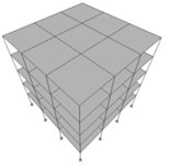
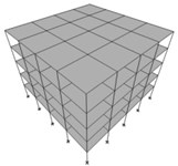
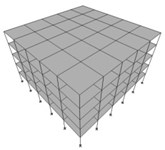
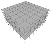
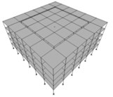
In order to divide an actual building’s structure into inner and outer parts with the aim of seismic response reduction by using the dynamic interaction between the two parts, the mass ratio of the inner and outer parts (Min/Mout) has to be compatible with the building’s architectural configuration. For example, in case of the regular and symmetric 5-story buildings, shown in Fig. 1, which has respectively 3, 4, 5 and 6 equal span bays in both main directions, the possible partitioning cases are shown in Fig. 2.
Fig. 1From left to right 3-, 4-, 5- and 6-bay buildings to be divided into two inner and outer parts
a)
b)
c)
d)
Fig. 2Dividing the structures of the buildings shown in Figure 1 into two inner and outer parts with various mass ratios of Min/Moutequal to a) 1/24, b) 1/8, c) 4/12 = 1/3, d) 9/16 and e) 16/20 = 4/5
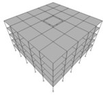
a)
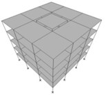
b)
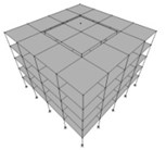
c)
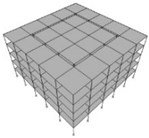
d)
e)
It is seen in Fig. 2 that only five values are architecturally possible for mass ratio of the inner and outer parts of the considered building. In order to find out that which one of these five cases results in the optimal partitioning, mass-wise, leading to the lowest level of the maximum inter-story drift values in both inner and outer substructures, a planar model of the building was created in a computer program, developed by the authors in MATLAB environment, as shown in Fig. 3.
Fig. 3Schematic view of the partitioned structure with a linking spring-damper at the roof level
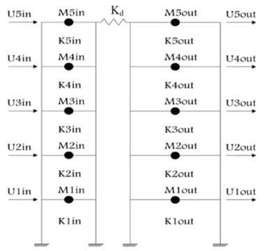
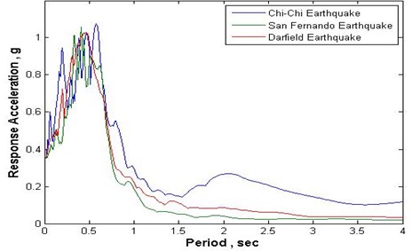
In the structural model, shown in Fig. 3, the left and right frames schematically show the inner and outer substructures respectively. In this model of the partitioned building’s structure all five mass ratios of the 5-story building, shown in Fig. 2, assuming a total mass of 100 tons for the whole building (Min+Mout= 100) were considered. First, the stiffness values of the stories of the undivided building were assigned so that, in accordance with UBC97 [7], the drift ratio limitation of 0.005, would be met, assuming the buildings to be of shear beam type. Then, the five mass ratios, shown in Fig. 2, were considered for the inner and outer substructures, and they were analyzed under the effect of Chi-Chi, San Fernando and Darfield earthquakes’ accelerograms, assuming a general 5 % damping for the structure. The specifications of the three employed earthquakes are given in Table 1 and their response spectra are shown in Fig. 4.
Table 1The specifications of the three employed earthquakes for conducting the THA required in the first part of analyses
Earthquake | PGA | Predominant period | Predominant acceleration |
Chi-Chi | 0.35g | 0.58 sec | 1.076 g |
San Fernando | 0.35g | 0.41 sec | 1.057 g |
Darfield | 0.35g | 0.44 sec | 1.026 g |
Fig. 4The response spectra of the three employed earthquakes or conducting the THA required in the first part of analyses
In these analyses, it was assumed that the spring-damper, linking the two inner and outer parts at the roof level, is a linear spring, and its appropriate stiffness value, Kd, in each case was found with respect to the stiffness of the 5th floor of the inner structure, K5IN, based on minimizing the maximum drift values in both inner and outer substructures, by repeating, for numerous times, the THA. For conducting the required THA cases the Ne Mark method was employed and formulated in the developed computer program in the MATLAB environment. In these analyses an increment of 0.01 of K5IN was considered for Kd, and the analyses werecontinued to the stage in which its value reached 0.5 times of K5IN, and in each case the maximum drift values were obtained, to find out which Kd value would lead to minimum amount of the maximum inter-story drifts in both inner and outer substructures. Figs. 5 to 7 shows the variation of the ratio of the maximum drifts in inner and outer substructures with respect to the original undivided structure, respectively for the three employed earthquakes, in case of Min/Mout= 9/16 (results related to other Min/Mout values can be found in the main report of the study [7]).
Fig. 5Ratios of the maximum inter-story drifts of the inner and outer substructures, with mass ratio of 9/16, to those of the original structure versus the link’s stiffness in the case of Chi-Chi earthquake
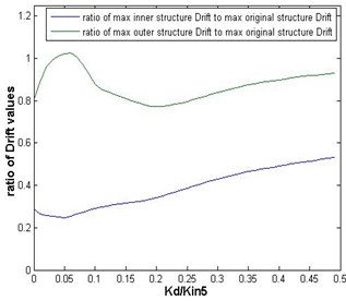
Fig. 6Ratios of the maximum inter-story drifts of the inner and outer substructures, with mass ratio of 9/16, to those of the original structure versus the link’s stiffness in the case of San Fernando earthquake
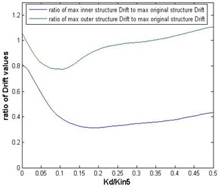
Fig. 7Ratios of the maximum inter-story drifts of the inner and outer substructures, with mass ratio of 9/16, to those of the original structure versus the link’s stiffness in the case of Darfield earthquake
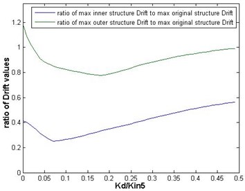
It is seen in Figs. 5 to 7 that the desired amounts of the link’s stiffness which leads to the minimum value of the maximum inter-story drifts are not the same for inner and outer substructures, and that the desired amount of the link’s stiffness is different for different earthquakes. However, as Figs. 5 to 7 show, the ranges in which these desired values vary, is not so wide, and it is logical to use a value of Kd= 0.15·K5IN as an optimal value for the case of Min/Mout= 9/16. Of course, the optimal value of Kd is not the same for different Min/Mout values. Table 2 presents the optimal values of Kd, obtained by THA, for all five Min/Mout ratios shown in Fig. 2.
It is observed in Table 2 that the amounts of inter-story drift ratio is well below the code limit in the inner substructure for all Min/Mout values, however, it can be realized that among the different Min/Mout ratios, given in the Table, the value of 9/16, with an optimal stiffness value of Kd= 0.15·K5IN would lead to the lowest level of the maximum inter-story drift values in the outer substructure. On this basis, the value of Min/Mout= 9/16 was chosen as the optimal.
In the next step, to create more energy dissipation capability in the spring-damper of the system, the linear link, connecting the inner and outer substructures to each other, was substituted by an elastic-perfectly plastic element, as a hysteretic damper, whose force-displacement relationship is shown graphically in Fig. 8.
Table 2Optimal stiffness of the linking spring, leading to the lowest level of the maximum inter-story drift value, for various Min/Mout ratios
Min/Mout | 1/24 | 1/8 | 1/3 | 9/16 | 4/5 |
Kd/K5IN | 0.09 | 0.08 | 0.13 | 0.15 | 0.11 |
Maximum drift ratio in the inner substructure | 0.0075 | 0.0074 | 0.0080 | 0.0078 | 0.0079 |
Maximum drift ratio in the outer substructure | 0.0225 | 0.0223 | 0.0240 | 0.0200 | 0.0212 |
Fig. 8Hysteresis of force-displacement relationship of the damper element
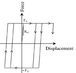
It is obvious that an optimal value of the yielding force, Fd, of the hysteretic damper, would result in the maximum energy dissipation capacity of the system. For finding this optimal value, a series of nonlinear time history analyses (NLTHA) were conducted, by using the computer program developed in MATLAB environment based on New Mark method, on the planar model of the partitioned building with Min/Mout= 9/16 and Kd= 0.15·K5IN. However, as it is clear that for higher energy absorption by the linking hysteretic damper, modal periods of the two inner and outer substructures, particularly their lower modes, should be well distant, it was tried to modify the stiffness values of the two substructures so that one of them would become relatively stiff and the other one relatively soft, to increase their interaction. The modification resulted in Tin= 0.30 sec and Tout= 0.90 sec.
Following the aforementioned modification, to find the optimal value of the yield displacement of the hysteretic damper, a range of 1 to 10 cm was considered for it, with an increment of 1 cm, and in each case the ratio of the maximum drift values of the inner and outer substructures to those of the original undivided structure were calculated. Figs. 9 to 11 show the variation of the ratios of the maximum inter-story drifts of inner and outer substructures to those of the original undivided structure versus the yield displacement of the hysteretic damper for the three employed earthquakes.
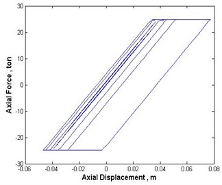
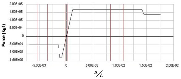
According to Figs. 9 to 11 an optimal yield displacement value 4 cm, in average, can be found for the hysteretic damper. As these figures show, by using this value for the yield displacement of the damper the maximum inter-story drifts of inner and outer substructures would decrease in average by almost 70 % and 20 %, respectively. Fig. 12 shows, as a sample, the hysteretic force displacement behavior of the damper with optimal stiffness and yield displacement values in the case of Chi-Chi earthquake.
As it can be seen in Fig. 12, the ultimate displacement in the damper, in this case, has been a little more than 7 cm, which is still less than 0.005 of the building height.
Fig. 9Ratios of the maximum inter-story drifts of the inner and outer substructures, with mass ratio of 9/16, to those of the original structure versus the link’s yield displacement in the case of Chi-Chi earthquake
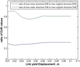
Fig. 10Ratios of the maximum inter-story drifts of the inner and outer substructures, with mass ratio of 9/16, to those of the original structure versus the link’s yield displacement in the case of San Fernando earthquake
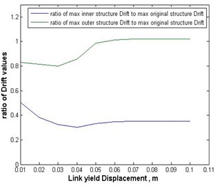
Fig. 11Ratios of the maximum inter-story drifts of the inner and outer substructures, with mass ratio of 9/16, to those of the original structure versus the link’s yield displacement in the case of Darfield earthquake
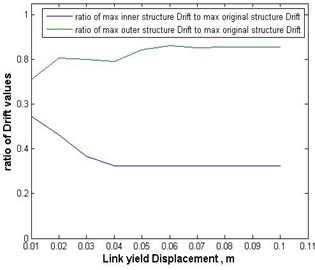
Fig. 12Force displacement graph of the hysteretic damper in the case of Chi-Chi earthquake
3. Application of “Structure partitioning” in 3D multi-story buildings
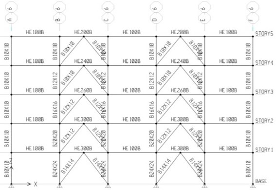
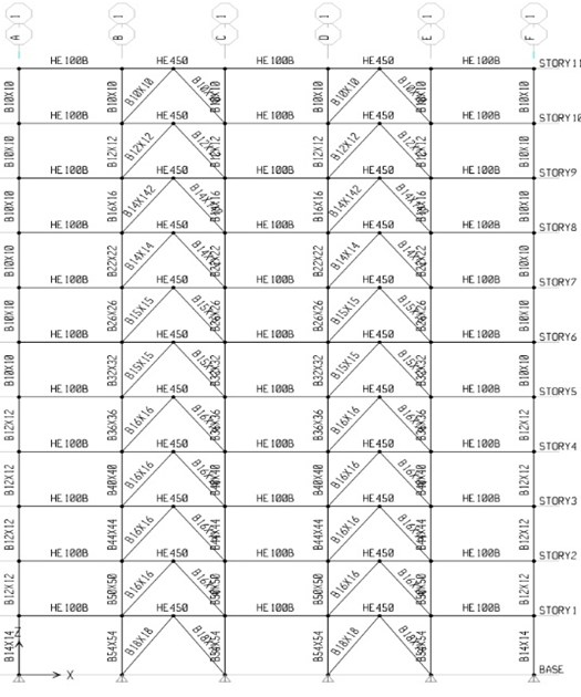
After finding the optimal values of stiffness and yield displacement of the hysteretic energy dissipating element, linking the two inner and outer substructures to each other at the roof level, as explained in the previous section of the paper, a set of the 5-, 8- and 11-story Chevron braced common steel buildings were considered, and first were designed by ETABS in accordance to UBC-97 [8], trying to have minimum over strength in their design. Figs. 13 to 15 show the typical plan and some sample frames of the designed buildings.
Fig. 13The typical plan of the designed multi-story buildings
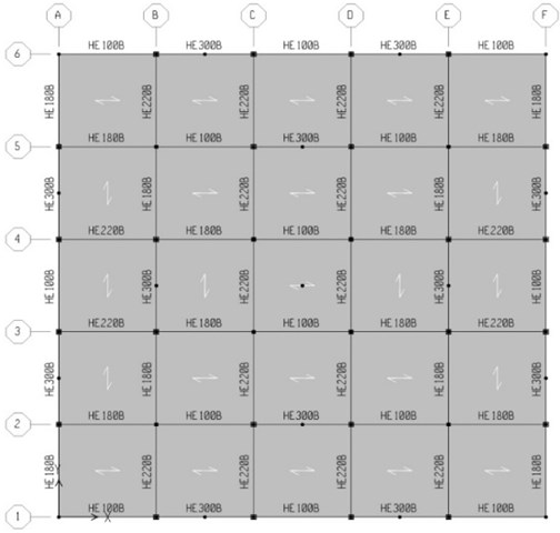
Fig. 14A sample frame of the designed 5-story building
In the next stage, the skeleton of each of the designed buildings was divided into inner and outer parts based on the optimal value of Min/Mout= 9/16, and considering elastic-perfectly plastic links between them at both directions at roof level and at the location of all columns locating at the interface of the two substructures in such a way that the sum of their stiffness in each direction becomes 0.15 times the stiffness of the upper story of the inner substructure. In dividing the building’s structures each column located at the interface of the inner and outer parts was substituted by two columns so that their axial load bearing capacity together becomes equal to that of the original individual column of the undivided structure. The hysteretic dampers were chosen of the ADAS type, and their yield displacement was considered to be the optimal value, obtained in the previous section. Fig. 17 shows the partitioned 5-story building with the considered hysteretic connecting links.
The partitioned structures were modeled in 3D by using PERFORM-3D computer program, and their NLTHA were performed under the effect of the three mentioned earthquakes. For these analyses the hysteretic behavior of beams, columns and bracing elements were considered in accordance with FEMA-356standard [9]. Fig. 18 shows an example of the nonlinear model for the axial behavior of bracing elements.
Fig. 15A sample frame of the designed 8-story building
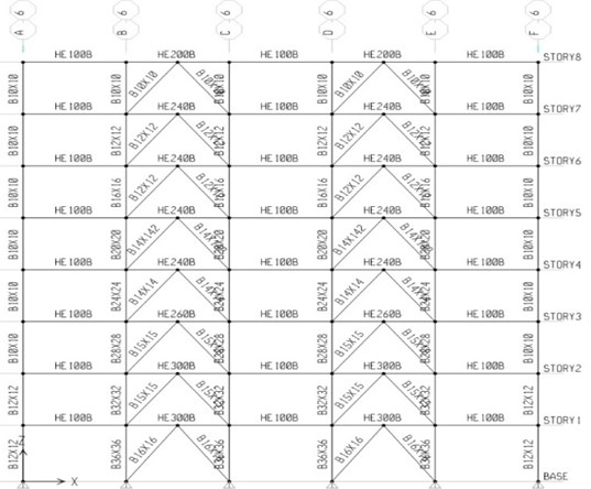
Fig. 16A sample frame of the designed 11-story building
According to the definition of the nonlinear behavior of braces, three performance levels of these members are considered, including 1) IO (Immediate occupancy), 2) LS (Life safety) and 3) CP (Collapse Prevention).
Based on the NLTHA by using a set of selected earthquake accelerograms, as explained in the next section, in case of 5-story building, considering the hysteretic dampers only at the roof level showed satisfactory response reduction, however, to achieve an acceptable level of seismic response reduction, in case of 8-story it was necessary to consider the hysteretic dampers at the 5th floor level in addition to the roof level, and in case of 11-story building it was required to consider the dampers at the 7th floor level in addition to the roof level.
Fig. 17The 3D view of the 5-bay 5-story building structure optimally divided, mass-wise, into inner and outer parts, connected to each other, at roof level, by hysteretic energy dissipating elements of ADAS type, with optimal initial stiffness and yield displacement
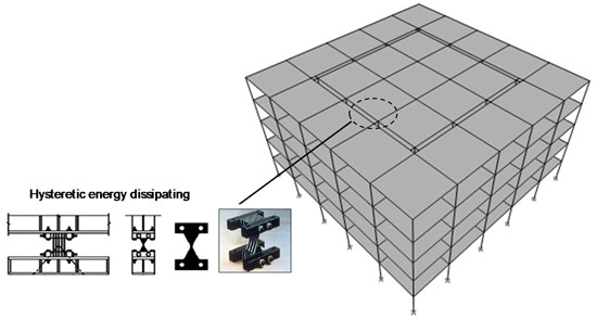
Fig. 18Generalized load-displacement curve of for a typical brace
3.1. The earthquake records selected for NLTHA
In this study, three groups of accelerogram pairs were selected, each pair having a dominant period close to that of original 5-, 8- or 11-story building, correspondingly. Table 3 summarizes the specifications of the selected accelerograms. All accelerograms were scaled in accordance with the regulations of ASCE-2010 standard [10].
3.2. Inter-story drifts obtained by NLTHA
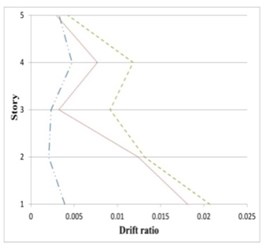
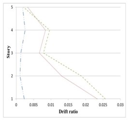
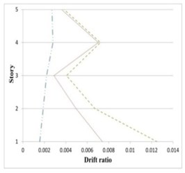
Figs. 19 to 21 show the inter-story drifts ratios of 5-, 8- and 11-story partitioned, and original buildings subjected to their corresponding earthquake records.
It can be seen in Figs. 19 to 21 that the inter-story drift ratios of all partitioned buildings are in most cases less than those of the original buildings. The amount of drift ratios reduction is in average 65 % and 25 % for inner and outer substructure, respectively, comparing to the original structure. In few cases the drift ratios in a middle story or the top story of the outer substructure is slightly higher than the original building, however in these cases the values of drift ratios are mostly less than 0.01.
Table 3Specifications of the employed earthquakes
Earthquake group for 5-story building | |||||
SF=SF1×SF2 | SF2 | SF1= 1/PGAMax | PGA | Component direction | Earthquake |
1.89 | 0.548 | 3.46 | 0.289 g | 0 degrees | Chi-Chi |
1.89 | 0.548 | 3.46 | 0.238 g | 90 degrees | |
1.89 | 0.548 | 3.46 | 0.161 g | Vertical | |
1.71 | 0.548 | 3.125 | 0.32 g | 0 degrees | San Fernando |
1.71 | 0.548 | 3.125 | 0.275 g | 90 degrees | |
1.71 | 0.548 | 3.125 | 0.167 g | Vertical | |
3.43 | 0.548 | 6.25 | 0.16 g | 0 degrees | Darfield |
3.43 | 0.548 | 6.25 | 0.16 g | 90 degrees | |
3.43 | 0.548 | 6.25 | 0.103 g | Vertical | |
Earthquake group for 8-story building | |||||
SF=SF1×SF2 | SF2 | SF1= 1/PGAMax | PGA | Component direction | Earthquake |
2.25 | 0.640 | 3.52 | 0.284 g | 0 degrees | Landers |
2.25 | 0.640 | 3.52 | 0.274 g | 90 degrees | |
2.25 | 0.640 | 3.52 | 0.181 g | Vertical | |
4.00 | 0.640 | 6.25 | 0.16 g | 0 degrees | Iwate |
4.00 | 0.640 | 6.25 | 0.142 g | 90 degrees | |
4.00 | 0.640 | 6.25 | 0.073 g | Vertical | |
4.25 | 0.640 | 6.63 | 0.151 g | 0 degrees | Duzce |
4.25 | 0.640 | 6.63 | 0.114 g | 90 degrees | |
4.25 | 0.640 | 6.63 | 0.105 g | Vertical | |
Earthquake group for 11-story building | |||||
SF=SF1×SF2 | SF2 | SF1=1/PGAMax | PGA | Component direction | Earthquake |
5.10 | 0.801 | 6.37 | 0.157 g | 0 degrees | Northridge |
5.10 | 0.801 | 6.37 | 0.133 g | 90 degrees | |
5.10 | 0.801 | 6.37 | 0.103 g | Vertical | |
2.25 | 0.801 | 2.81 | 0.356 g | 0 degrees | Chuetsu |
2.25 | 0.801 | 2.81 | 0.325 g | 90 degrees | |
2.25 | 0.801 | 2.81 | 0.136 g | Vertical | |
5.89 | 0.801 | 7.35 | 0.136 g | 0 degrees | Italy-CTR |
5.89 | 0.801 | 7.35 | 0.126 g | 90 degrees | |
5.89 | 0.801 | 7.35 | 0.054 g | Vertical | |
Fig. 19Maximum inter-story drifts of partitioned and original 5-story buildings subjected to the corresponding earthquakes
a) Chi-Chi
b) Darfield
c) San Fernando

Fig. 20Maximum inter-story drifts of partitioned and original 8-story buildings subjected to the corresponding earthquakes
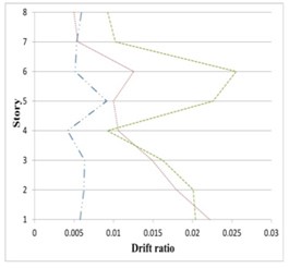
a) Duzce
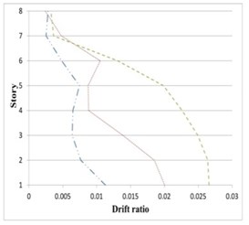
b) Iwate
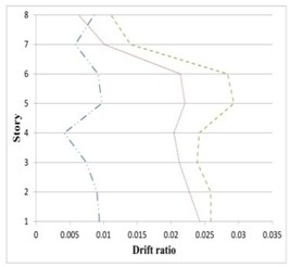
c) Landers

Fig. 21Maximum inter-story drifts of partitioned and original 11-story buildings subjected to the corresponding earthquakes
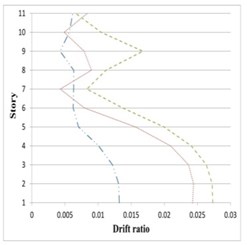
a) Northridge
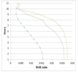
b) Chuetsu
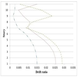
c) Italy-CTR

4. The observed performance level based on formation of plastic hinges
Figs. 22 to 24 show the performance level of the structural elements, respectively in 5-, 8- and 11-story original and partitioned buildings, based on formation of plastic hinges.
As can be seen in Figs. 22 to 24, partitioned structures have performed in IO to LS levels, while the performance of the original structures has mostly in CP level. Although the performance level obtained based on the plastic hinge formation, clearly shows the enhanced resilience of the partitioned structures subjected to earthquake, to create more confidence about the seismic performance of the original and partitioned structures the Park-Ang damage index was also calculated for them as described in the next section.
5. Park-Ang damage index in the original and partitioned structures
Park-Ang damage index is a linear combination of deformation ratios and absorbed hysteretic energy, and is defined by the following formula according to ATC-40 standard [11]:
where, δM is the maximum deformation of the structure obtained from NLTHA of the structure under the effect of earthquake, δu is the ultimate deformation of the structure obtained from nonlinear static analysis of the structure under uniform loading pattern, Qy is the yield strength of the desired member, Eh is the absorbed hysteretic energy by the member under the earthquake, and β is a non-negative parameter representing the effect of cyclic loading on structural damage, varying between 0.10 and 0.15 (was considered as 0.10 in the present study).
Fig. 22Performance level of the: a) structural elements in 5-story original, b) partitioned buildings subjected to the corresponding earthquakes

a) Subjected to Chi-Chi earthquake

b) Subjected to Darfield earthquake

c) Subjected to San Fernando earthquake

Fig. 23Performance level of the: a) structural elements in 8-story original, b) partitioned buildings subjected to the corresponding earthquakes
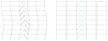
a) Subjected to Duzce earthquake
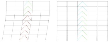
b) Subjected to Iwate earthquake
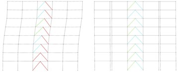
c) Subjected to Landers earthquake

Fig. 24Performance level of the: a) structural elements in 11-story original, b) partitioned buildings subjected to the corresponding earthquakes
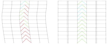
a) Subjected to Northridge earthquake
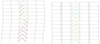
b) Subjected to Italya-CTR earthquake
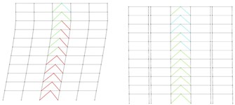
c) Subjected to Chuetsu earthquake

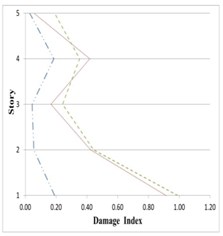
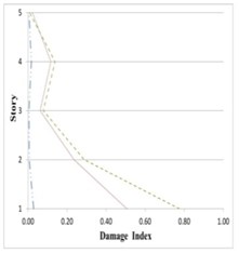
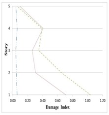
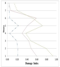
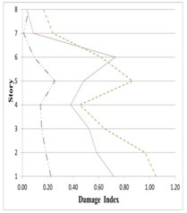
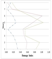
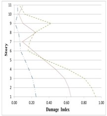
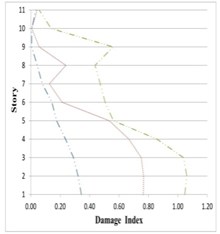
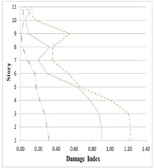
To calculate the damage index of the buildings’ stories, the damage to the beams, columns and bracings elements was first calculated for each story. Then, using the weight coefficient β, based on dissipated hysteretic energy by the story components, the story damage was calculated. Table 4 shows different structural performance levels based on Park-Ang damage index indicated in ATC-40 Standard [11] and Figs. 25 to 27 show Park-Ang damage index in various stories of the 5, 8 and 11-story original and partitioned buildings.
As can be seen in Figs. 25 to 27, damage indices in the lower stories all 5-, 8- and 11-story buildings in the inner and outer substructures has decreased respectively about 80 % and 25 %, comparing to the original structure. The amount of this decreases for the middle stories are respectively around 75 % and 10 %, and for the upper stories about 60 % and 5 %. On this basis, it can be said that the proposed partitioning significantly decreases the damage level in building structures.
Fig. 25Variation of Park-Ang damage along the height of partitioned and original 5-story buildings subjected to the corresponding earthquakes
a) Chi-Chi
b) Darfield
c) San Fernando

Fig. 26Variation of Park-Ang damage index along the height of partitioned and original 8-story buildings subjected to the corresponding earthquakes
a) Duzce
b) Iwate
c) Landers

Fig. 27Variation of Park-Ang damage index along the height of partitioned and original 11-story buildings subjected to the corresponding earthquakes
a) Northridge
b) Chuetsu
c) Italya-CTR

Table 4Park-Ang damage index for different levels of performance
Park-Ang damage index | Performance level |
0-0.2 | IO (Immediate occupancy) |
0.2-0.5 | LS (Life safety) |
0.5-0.8 | CP (Collapse prevention) |
6. Conclusions
In this study, three 5-, 8- and 11-story buildings were divided optimally, mass-wise, into inner and outer parts and were connected to each other, at top and some lower levels, by the yielding energy dissipating elements or hysteretic dampers. The original and partitioned buildings then were seismically evaluated, by nonlinear time history analysis under the effect of several selected earthquakes, and their responses were compared. On this basis, the following conclusions can be made:
The optimal mass ratio of the inner to outer substructures, applicable from the architectural point of view, was obtained based on the minimal inter-story drifts as Min/Mout= 9/16.
The optimal stiffness of the stories of the inner and outer parts of the 5-story partitioned building was such that the first mode periods of the inner and outer structures were 0.40 sec and 0.90 sec, respectively.
In case of 5-story building, the optimal initial stiffness and yielding displacement of the hysteretic energy dissipating elements were obtained based on minimal inter-story drift values as Kd= 0.15·K5IN and 4 cm.
Installation of energy dissipating elements with optimal stiffness and yielding displacement strength at the roof level of the 5-story building, top and 5th story level of the 8-story building, and roof and 7th story level of the 11-story buildings, resulted in maximum inter-story drift reductions of the outer and inner substructures, which were about 20 % and 65 % in average, respectively in the outer and inner substructures in comparison to the original structures.
The plastic hinges formed in the original structures were in the CP performance level, while in the partitioned structure they were in LS and IO levels.
Moreover, the Park-Ang damage indices of the 5-, 8- and 11-story partitioned buildings decreased about 20 % and 80 % respectively for the outer and inner substructures in comparison to the original structure.
Based on the above facts, it can be said that partitioning the building’s structure into inner and outer interactive substructures can be used as an effective technique for seismic response reduction of building systems and achieving the goal of creating repairable building structures.
References
-
Bhaskararao A. V., Jangid R. S. Seismic response of adjacent buildings connected with dampers. 13th World Conference on Earthquake Engineering, Vancouver, Canada, 2004, p. 3143-3157.
-
Ziyaiefar M. Vertical seismic isolation method in steel structures against earthquake. 6th International Conference on Seismology and Earthquake Engineering, International Institute of Seismology and Earthquake Engineering, 2006, p. 1611-1620.
-
Su Kim H., Jin Kim Y. Control performance evaluation of shared tuned mass damper. Advanced Science and Technology Letters, Vol. 69, 2014, http://dx.doi.org/10.14257/astl.2014.69.01.
-
Annapurna V. B., Vankudre S. B. Vibration control of adjacent buildings connected with selected types of dampers. International Journal of Engineering Research and Technology, Vol. 3, Issue 6, 2014, p. 1431-1436.
-
Abdelraheem Farghaly A. Optimization of viscous dampers with the influence of soil structure interaction on response of two adjacent buildings under seismic load. IOSR Journal of Engineering (IOSRJEN), Vol. 4, Issue 1, 2014, p. 18-27.
-
Jamshidi J., Hosseini M. Dividing the building structure into two parts with dynamic interaction. 2ndInternational Conference on Earthquake Resistant City, 2015, p. 352-360.
-
Taheri A. Dividing the Building’s Skeleton into Two Inner and Outer Interactive Parts and Using Yielding Dampers between them for Seismic Response Reduction. Ph.D. Dissertation, Arak Branch of the Islamic Azad University, Iran, 2017.
-
Uniform Building Code, Structural Engineering Design Provisions (Uniform Building Code, Vol. 2: Structural Engineering Design Provisions), 1997.
-
American Society of Civil Engineers, minimum design loads for buildings and other structures, 2010.
-
Pre-standard and Commentary for the Seismic Rehabilitation of Buildings. Federal Emergency Management Agency, FEMA-356, 2006.
-
ATC-40, Applied Technology Council, California Seismic Safety Commission, 1998.
