Abstract
The Bidirectional Three Port Converter (BTPC) proposed in this research work is addressed for an elevator application that is driven from a BLDC motor in all four quadrants sourced from solar Photovoltaic (PV). The converter design of a PV based system necessitates constant output voltage with high power density and efficiency. The Proposed BTPC tracks the maximum power, maintains constant output voltage and also deals with the bidirectional power flow management whenever there is a change in applied torque when the machine is switched from motoring to regenerating mode. Furthermore, single stage power conversion is achieved with power transfer from PV to dc link or battery to dc link based on the load requirement and surplus power is directly stored in the battery. Closed loop control ensures adjusting the duty cycle of the proposed converter switches thereby maintaining the bidirectional power flow management. The proposed converter is analysed in detail with operating principle, design considerations and verified in terms of simulation and through experimental results.
1. Introduction
The need for an effective and efficient way of transporting people and goods employing elevators has become inevitable nowadays due to the vertical growth of the buildings. In common, three phase induction motors are wide spread used for the hoisting operation in these elevators that became a part of the basic infrastructure in high rise buildings. There are considerable researches that aimed at replacing the conventional motor to upgrade the speed, thereby improving the reliability [1-3]. BLDC is in par with these motors in lieu of its advantage of being electronically commutated with high torque/current ratio and high power density making it better choice to replace the conventional motors [4]. Quite a lot number of studies have showed better efficiency of BLDC motors with superior control [5]. Furthermore, the possibility of regenerative braking and ease of control of BLDC motors have triggered its application in elevator system which is detailed in this research paper.
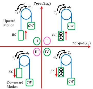
Fig. 1, illustrates the four quadrant operation of the elevator system. The elevator working depends on the relative weight of the Elevator Cabin (EC) with respect to the counterweight (CW) and the direction of movement of the EC. Quadrants I and IV are an indicative of the EC carrying passengers and quadrants II and III indicates empty cabin. The forward and reverse rotation of the BLDC motor corresponds to the upward lifting and downward towing motion of the EC. In the first quadrant of operation, the net weight of EC is high comparable to its counter weight. Hence EC demands upward motion necessitating the BLDC machine to work as motor (forward motoring) maintaining torque and rotational speed in the same direction. Likewise, the reverse motoring operation of BLDC motor occurs in the third quadrant when net EC weight becomes less comparable to counter weight leading to the downward movement of the EC. With the net weight of the EC lesser than the counter weight in second quadrant, BLDC machine now regenerates (forward braking) to lift the EC upwards developing a braking torque. Similarly, when the net weight of the EC is high comparable to the counter weight, BLDC machine is subjected to the reverse braking in fourth quadrant tending to produce a positive torque as shown in Fig. 1.
Fig. 1Four possible modes of an elevator system
In multistage converters that are capable of controlling each input (PV, battery) individually for standalone operation, the energy to charge the battery takes place in two stages. The energy is delivered to the load or the common bus in first stage and then to charge the battery in the next stage [6, 7]. The need for integration of renewable energy with the energy storage systems due to its uncertainty has led to the research of different converter topologies [11, 12]. The advent of isolated three port converter enables interfacing of multiple energy sources has developed a compact structure at low cost [8-10]. Research on different topologies for three port dc-dc converters have shown a remarkable progress in the design of converters due to its increasing attention towards integrating renewable energy and energy storage systems [11, 12]. A standalone single stage converter with domain distribution for renewable energy application discusses on an effective approach to extract the maximum solar power to meet load demand and to store the excess energy in the battery using a bidirectional converter [15]. A three port converter named boost bidirectional buck converter (B3C) proposed in the paper [13] interfaces PV port, battery port and load port features single stage power conversion with the operation shunted between conductance mode and MPPT mode. However, the converter suffers drawback of power being fully transferred to the load port through DC link and then the excess power returned back to the battery from the dc link. This involves unnecessary losses during power transit from DC link to battery. This TPC however, features high integration, single stage power conversion, and less electromagnetic noise has limited power flow arrangement.
This paper presents a novel PV and battery powered elevator system using BTPC. The BTPC is employed for integrates the three different ports such as PV, battery and load in single stage. The drawbacks due to the unwanted losses incurred owing to the power transfer from DC link to battery in B3C converter [13] is overcome by the proposed BTPC by sending the required amount of power to the load and transferring the excess power directly to the battery. The BTPC extorts the maximum power from PV module using MPPT algorithm. Furthermore, the BTPC upholds the constant output voltage at the load end when the PV generated power and load demand is at variance. With the increasing load demand, the load voltage drops significantly from its reference value. Meantime, battery will discharge to bestow the additional demand. In the same way, with the drop-in load demand, load voltage increases with respect to its reference value. Subsequently, the excess power will sink into the battery. The paper is organized as follows. Section 2 explains the proposed BTPC based BLDC drive, Section 3 details the different modes of operation of BTPC under motoring/generating conditions, Section 4 describes the control system of the proposed converter, Section 5 discusses the simulations results and finally the Section 6 discusses the experimental prototype results.
2. Proposed BTPC fed BLDC motor driver
Fig. 2, shows the proposed BTPC fed BLDC motor driver. A PV followed by the converter feeds a VSC and driving a BLDC motor. The BTPC based BLDC driver circuit comprises of a PV module, input inductors ( and ), unidirectional switches (, and ), bi-directional switch (, power diode (), storage battery, output capacitor (, VSC switches (to ), and BLDC motor. The bidirectional switch (i.e. two unidirectional switches are connected in appropriate way) is used to block voltages in both directions, so it allows the current flow in both directions (bi-directional).
Fig. 2Proposed BTPC fed BLDC Motor driver
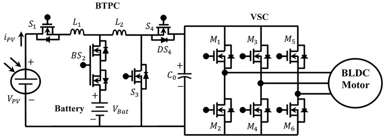
Generally, BTPC must be regulated to meet the BLDC motor (load) requirements, similarly the PV port must amend to harvest the maximum energy, and the battery port should be regulated to realize the battery management. These tasks can be comprehended using four control degrees of freedom, one that regulates the PV port voltage enabling PV in MPPT mode using switch (); the second degree of freedom controls the current through ( and ) via switch (), regulating battery management when sunlight or load port voltage regulation eclipse; third one controls the load port current for load port voltage regulation by switch (); Finally, the fourth degree of freedom controls the bidirectional current of BLDC motor during forward/reverse braking conditions by means of switch (. The four power switches are the main controllable elements that control the PV port, load port and battery of the converter. Here the proposed converter acts as a single stage BTPC to facilitate the bidirectional power flow between load and battery.
3. Working principle of BTPC
The proposed converter is intended to work in two power flow modes such as motor and generator. , , and represent the pulse input to the four switches. , , , , , and are the current through the inductors and , PV, Battery, anti-parallel diode of switch and , BTPC current respectively. , , , , , , , and are the voltage through the switches , , and , PV, Battery, anti-parallel diode of switch and , BTPC voltage respectively.The circuit operation is analyzed based on the assumption that all switches are assumed to be ideal and the capacitors are large enough so that the voltage ripples due to switching are negligible.
3.1. Modes of operation and analysis under motoring mode
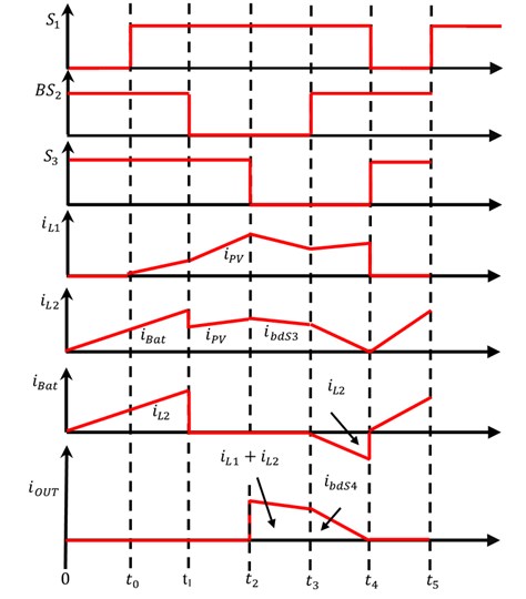
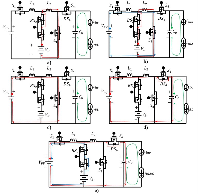
In the first and third quadrant, both the speed and the torque is either positive (forward motoring) or both negative (reverse motoring). In this motor mode, capacitor () is discharged and deliver its stored energy to BLDC motor via VSC. In this motoring mode switch is entirely off state. Fig. 3, shows the waveforms of the proposed BTPC functions under motoring mode. During interval (0 to ), switches and turns ON, while is off state. The Inductor is energized from the battery and hence inductor current starts increasing. During interval ( to ), switch is also turned ON. Hence inductor is charged from the PV and meanwhile the inductor is kept charged via the battery. In the interval ( to ), the bidirectional switch is off state. With switches and turned ON, both the inductors and are charged from the available PV supply. During interval ( to ), switches and are off state. With switch turned ON, the load voltage across the capacitor increases via the PV panel and through the discharge of inductors and . During interval ( to ), switches and turns ON, while is reverse biased. The battery gets energized from the PV and inductor current. At the same time, output capacitor is energized from PV and both the inductors. Hence the capacitor voltage increases via body diode of switch . Thus, under motoring modes, PV and battery ports are regulated to maintain continuous supply to the load. Fig. 4, shows the operation of BTPC under different intervals during motoring mode. The equation of current at every interval is derived as below.
The current equations of interval 1 () are as follows:
The current equations of interval 2 () are as follows:
where .
The current equations of interval 3 () are as follows:
The current equations of interval 4 () are as follows:
The current equations of interval 5 () are as follows:
Fig. 3Waveforms of proposed BTPC functions under motoring mode
3.2. Output voltage and duty cycle calculation
Assume the summation of current (, , , , ) in the entire time interval [i.e. -] is equal to zero:
where ; ; .
The duty ratio of BTPC switches , and respectively:
where, () represents one switching period. Hence, the output voltage equation is derived by:
In fact, Eq. (10) confirms this fact that the proposed converter voltage will regulated, consequently the state (charging/discharging) of the battery will regulated based on the duty cycle.
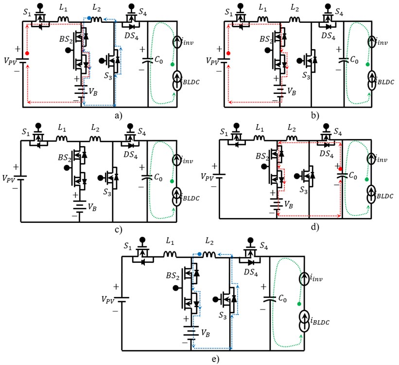
Fig. 4Proposed BTPC when operate in motor mode: a) interval 1, b) interval 2, c) interval 3, d) interval 4, e) interval 5
3.3. Modes of operation and analysis under generating mode
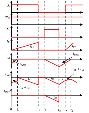
The BLDC drive operates in generator mode in the second and the fourth quadrant. Either the torque is negative with positive speed (Forward generating) or the speed is negative with positive torque (Reverse generating). Fig. 5, shows the waveform of the proposed BTPC under generating mode. During interval ( to ), switches and are turned ON and switch is off state, while switch is reverse biased. Hence the battery is energized from PV and inductor . In the interim, the inductor delivers its stored energy to battery via body diode of switch . In the interval between ( to ), with the switches in same state, the battery current further increases due to the discharged energy from PV and inductor ,whereas the inductor current is zero as it is completely discharged.
The interval between ( to ), the bidirectional switch is turned ON, nevertheless there is no current flow through battery as no energy is left in both the inductors. Now during the interval between ( to ), the switches and are turned ON. Hence the capacitor deliveredits stored energy to inductor and battery, so inductor and battery current increases. In this interval, the regenerative energy of BLDC motor is effectively retrieved and stored in battery via BTPC. In the Interval between ( to ), bidirectional switch alone is turned ON, whereas the remaining switches are off state. With in ON state, the stored energy in the inductor is delivered to the battery via body diode of . Fig. 6, shows the operation of converter under different intervals during generating mode.
Fig. 5Waveforms of proposed BTPC under generating mode
The current equations of interval 1 () are as follows:
where .
The current equations of interval 2 () are as follows:
The current equations of interval 3 () are as follows:
The current equations of interval 4 () are as follows:
The current equations of interval 5 () are as follows:
Fig. 6Proposed BTPC when operate in generator mode: a) interval 1, b) interval 2, c) interval 3, d) interval 4, e) interval 5
3.4. Output voltage and duty cycle calculation
Assume the summation of current (, , , , ) in the entire time interval [0-] is equal to zero:
where:
and represents duty cycles; denotes output capacitor voltage at sampling instant .
Therefore, the derived output voltage equation is:
In fact, Eq. (18) confirms this fact that the proposed BTPC converter voltage will be regulated and consequently the state (charging/discharging) of the battery will regulated based on the duty cycle.
4. Control system of proposed converter
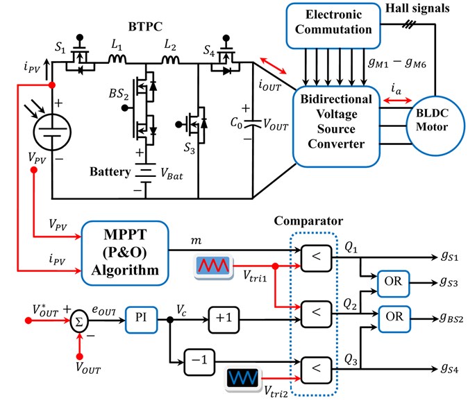
The control method of the proposed system is explained in this section. Fig. 7, shows the control segment of the proposed BTPC. The basic perturb and observe (P&O) algorithm is employed in the MPPT network in PV system to draw the maximum power from the solar module irrespective of weather conditions. (-modulation index) is the output of the MPPT algorithm, ( and ) is the voltage and current of PV module, () is the peak value of the carrier voltage. If the modulation index () is compared with the carrier voltage (), i.e., (), this will lead to PWM generation of (). For output regulation, the output voltage () is measured and compared with a voltage reference () and the difference in voltage () is amplified according to the gain of the controller that delivers a control voltage ():
where stands for the th sampling instant. The control voltage is derived by:
where and refers to the respective proportional and integral gains of the voltage controller.
When output voltage is lesser than voltage reference (i.e. ), control voltage () is compared with the carrier voltage 1 (), i.e., (), leading to the PWM generation of (). If the output voltage is greater than voltage reference (i.e. ), control voltage () is compared with the carrier voltage 2 (), which is shifted in phase by 180 degrees from i.e., (), leads to the PWM generation of (. The gate pulses of BTPC switches (, , and ) are generated by using a logical OR operator given by the following equations:
The BLDC motor is fed by the VSC, where the firing pulses () for the switches are determined by the appropriate switching logic based on the rotor position sensed by the Hall Effect sensor as shown in Fig. 7.
Fig. 7Control segment of BTPC
5. Simulation results
The simulation results of the proposed converter fed BLDC drive is discussed in this section. The input voltage sources such as PV and battery are considered as (18 V), (12 V). The output voltage of the BTPC is desired to be regulated on (24 V). The BLDC motor of power rating 40 W (rotor speed = 3000 rpm, rated dc link voltage = 24 V, load torque = 0.125 Nm and number of poles = 8) is taken at the load port of the proposed system.
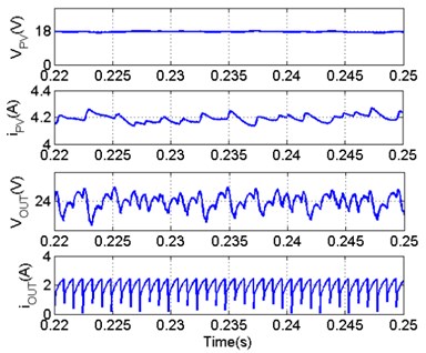
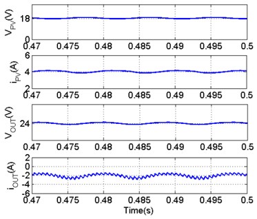
The performance evaluation of BTPC under forward motoring and generating modes are discussed as follows. Assume, PV receives maximum irradiance (1000 W/m2) in both cases; therefore generated 75 W PV power is shown in Fig. 8(a). In the forward motoring mode, in the interval “between 0 to 0.25 s”, a torque of 0.125 Nm and speed of 3000 rpm is impressed on the BLDC motor as shown in the Fig. 8(b) and (c) respectively. In this operating mode PV is sufficient to supply the 40 W BLDC motor, therefore the surplus PV power of 31.6 W is efficiently delivered to the battery through BTPC. The BTPC delivers 40 W of electrical power to VSC and VSC delivers 38.13 W of electrical power to BLDC motor as shown in the Fig. 8(d) and (e) respectively. At 0.25 s, the torque is suddenly changed to -0.125Nm as shown in Fig. 8(b) and hence the speed of the BLDC motor exceeds the synchronous speed driving the machine to generating mode as shown in Fig. 8(c). Now the BLDC motor delivers 58.75 W electrical power to VSC in opposite direction and VSC delivers 55.32 W electrical power to BTPC in opposite direction as shown in Fig. 8(d) and (e) respectively. Hence surplus PV power and regenerative power from BLDC motor (totally 118.68 W) is efficiently delivered to the battery through BTPC as shown in the Fig. 8(f). Information on various parameters is obtained from simulation results. PV parameters and BTPC parameters for motoring and generating modes are shown in the Fig. 9(a) and 9(b). It includes the PV voltage, PV current, BTPC voltage and BTPC current respectively.
Fig. 8Performance evaluation of BTPC under forward motoring and forward generating modes

a)

b)

c)

d)

e)

f)

g)
Fig. 9PV and BTPC parameters under: a) motoring mode, b) generating mode
a)
b)
6. Experimental validation
To evaluate the performance of the BTPC fed BLDC drive when operates under motor and generator mode have been modeled and tested by laboratory prototype. PV panel (SOLIS type) with a maximum power of 100 W at 1000 W/m2 insolation as an input source. The energy storage element used is an Amardeep and Co AT 12 V, 12 A rechargeable lead-acid battery. A GM33Y-36A150 BLDC motor acts as the load to the system. For the converter, semiconductor device, MOSFET IRFP4110PbF is chosen due to its low turn-on resistance (3.7 mΩ) that can proficiently lessen the conduction loss of the MOSFET in a single-stage converter. A BTPC is employed for PV, Battery and BLDC motor, which automatically varies the duty cycle in order to regulate the output voltage by means of constant. The output voltage is connected to a VSC, which is controlled by electronic commutation. The rotor position information is obtained by hall-effect position signals. The hardware block diagram of proposed system is shown in Fig. 10. The 16-bit dsPIC30F4011 controller is used to generate the gate pulses for BTPC and VSC in real-time. As it can be seen in Fig. 10, a MOSFET driver allows a low current digital output signal to drive the gate of a MOSFET. A 5 volt digital signal can switch a high voltage MOSFET using the driver. Opto isolator (NTE3092) functions as a galvanic isolation component establishing connection between two devices without direction conduction.
Fig. 10Hardware block diagram of proposed system
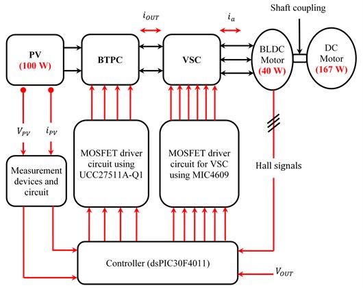
The UCC27511A-Q1 is high speed MOSFET driver for BTPC switches. It requires low current digital signals to drive power MOSFET’s. The MIC4609 is a 3-phase MOSFET driver for VSC. The robust operation of the MIC4609 ensures that the outputs are not affected by supply glitches, high side ringing below ground. Moreover, voltage sag protection is provided on both the low-side and high-side drivers. Hall signal filtering and power circuitries are also developed for the Hall-effect position sensors.
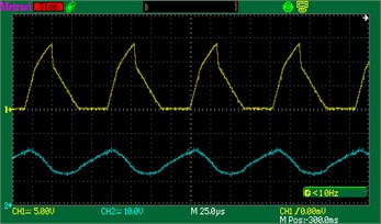
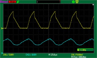
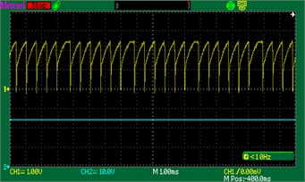
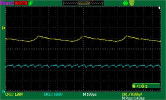
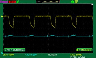
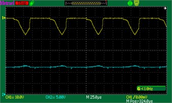
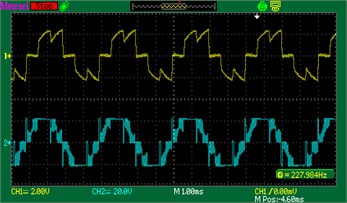
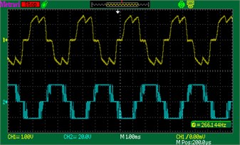
The experiment verification of proposed system under forward motoring and generating modes are shown in Fig. 11. Information on various parameters is obtained from oscilloscope recorded waveforms. The first set of waveform of motor mode [see Figs. 11(a)-(d)] shows the PV current and voltage, the BTPC current and voltage, the battery current and voltage and the stator current and stator voltage of the BLDC motor respectively. As shown in these figures, PV panel receives solar insolation and delivers the maximum power of 69.1 W (18 V, 3.83 A) at a particular instant is shown in Fig. 11(a). The output voltage of the BTPC is set at 24 V. The BTPC is maintained at the desired reference value, therefore it regulates the power of 41.2 W (24 V, 1.7 A) is shown in Fig. 11(b). The BLDC motor with a rated power of 40 W, 2500 r/min, 0.14 Nm is a load port of the proposed system. Now PV is sufficient to supply the 41.2 W BLDC motor, therefore the surplus PV power of 23.83 W (14 V, 1.7 A) is efficiently delivered to the battery through BTPC is shown in Fig. 11(c). The stator current and stator voltage of BLDC motor during motor mode is shown in Fig. 11(d). In addition, the second set of waveform of generator mode [see Fig. 11(e)-(h)] shows same parameters as mentioned in motor mode. As shown in these figures, PV panel receives solar insolation and delivers the maximum power of 68.9 W (18 V, 3.82 A) at a particular instant is shown in Fig. 11(e). The dc motor (Model no:75ZYT110-2445) with a rated power of 167 W, 4000 r/min, 0.4 Nm is coupled with a BLDC motor to drive above synchronous speed lashing it to regenerating mode and delivers the electrical power of 29.7 W (24 V, 1.23 A) in opposite direction is shown in Fig. 11(f). Therefore, PV and load power is delivered to the battery through BTPC as shown in the Fig. 11(g). The stator current and stator voltage of BLDC motor during generator mode is shown in Fig. 11(h).
Fig. 11Recorded oscilloscope waveforms of proposed system: a)-d) motor mode; e)-h) generator mode
a)
e)
b)
f)
c)
g)
d)
h)
7. Performance comparison
The performance of the proposed converter is compared with the existing three port converter [13] in this section. The proposed three port converter with single stage power conversion is compared with the existing non isolated three port converter in terms of power flow and losses under motoring and generating mode.
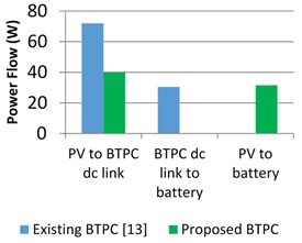
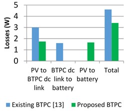
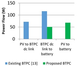
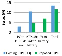
The existing converter in the motoring mode, transfers a power of 72 W from PV to BTPC dc link, whereas in the proposed converter power of 40 W is alone transferred to the BTPC dc link. Furthermore, the excess power of 30.4 W from BTPC dc link is returned to battery based on the load requirement in the existing converter, whereas excess power of 31.6 W is directly stored to the battery from PV itself in the proposed converter as shown in the Fig. 12(a). A loss of 3 W and 1.6 W is incurred in the existing converter during power flow from PV to dc link and from dc link to battery with total loss accounting to 4.6 W in the existing converter in motoring mode. Whereas, the proposed converter suffer a power loss of 1.74 W and 1.66 W during power flow from PV to dc link and from PV to battery with total loss of 3.4 W as shown in Fig. 12(b). Similarly, in generating mode, in the existing converter, a power of 72 W is transferred from PV to BTPC dc link and 116.8 W from BTPC dc link to battery with losses of 3 W and 10.52 W respectively during the power flow. Whereas in the proposed converter, power of 50.6 W and 68.08 W is transferred from dc link to battery and from PV to battery itself with losses incurred during this power flow of 4.72 W and 6.92 W respectively as shown in Fig. 12(c) and (d).
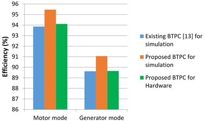
Thus, an overall efficiency of 93.86 % and 89.6 % is obtained through the simulation results in the existing converter during motoring and generating mode respectively. Whereas, in the proposed converter, an overall efficiency of 95.46 % and 91.06 % is obtained through the simulation results during motoring and generating mode respectively. Also, the results are validated through hardware experiment in the proposed converter showing a considerable efficiency of 94.1 % and 89.7 % in motoring and generating mode respectively as shown in Fig. 13.
Fig. 12Power flow and losses estimation of conventional and proposed BTPC a) and b) for motor mode c) and d) for generator mode
a)
b)
c)
d)
Fig. 13Efficiency analysis of conventional and proposed BTPC
8. Conclusions
This paper presents the theoretical analysis, simulation and experimental results of the proposed BTPC for elevator applications. A BLDC motor of power rating 40 W is taken at the load port of the proposed system. When BLDC motor operates in forward motoring mode, where losses are reduced by 26 % compared to the existing converter [13] generating an overall efficiency of 95.46 % through simulation and 94.1 % experimentally. With the change in applied torque, the machine is driven into regenerating mode where power from the BLDC motor is efficiently delivered to the battery through BTPC with overall reduction in losses by 14 % compared to the existing converter generating an overall efficiency of 91.06 % through simulation and 89.7 % experimentally. Thus, the proposed converter has the benefit of utilizing less number of components with an apparent topology for single stage power conversion resulting in improved efficiency which are verified through simulation and experimental results.
References
-
Wrzecionko B., Looser A., Kolar J. W., Casey M. High-temperature (250 °C/ 500 °F) 19000 min-1 BLDC fan for forced air-cooling of advanced automotive power electronics. IEEE/ASME Transactions on Mechatronics, Vol. 20, Issue 1, 2015, p. 37-49.
-
Yang F., Jiang C., Taylor A., Bai H., Kotrba A., Yetkin A., Gundogan A. Design of a high-efficiency minimum-torque-ripple 12-V/1-kW three-phase BLDC motor drive system for diesel engine emission reductions. IEEE Transactions on Vehicular Technology, Vol. 63, Issue 7, 2014, p. 3107-3115.
-
Jung E., Yoo H., Sul S.-K., Choi H.-S., Choi Y.-Y. A nine-phase permanent-magnet motor drive system for an ultra-high-speed elevator. IEEE Transactions on Industrial Applications, Vol. 48, Issue 3, 2012, p. 987-995.
-
Xia Chang Liang Permanent Magnet Brushless DC Motor Drives and Controls. John Wiley and Sons, 2012.
-
Shanmugasundram R., Zakariah K. M., Yadaiah N. Implementation and performance analysis of digital controllers for brushless DC motor drives. IEEE/ASME Transactions on Mechatronics, Vol. 19, Issue 1, 2014, p. 213-224.
-
Sun Kai, Li Zhang, Yan Xing, Josep Guerrero M. A distributed control strategy based on dc bus signaling for modular photovoltaic generation system with battery energy storage. IEEE Transactions on Power Electronics, Vol. 26, Issue 10, 2011, p. 3032-3045.
-
Locment Fabrice, Manuela Sechilariu, Issam Houssamo DC load and batteries control limitations for photovoltaic systems: experimental validation. IEEE Transactions on Power Electronics, Vol. 27, Issue 9, 2012, p. 4030-4038.
-
Zhan Wang, Li Hui An integrated three-port bidirectional DC-DC converter for PV application on a DC distribution system. IEEE Transactions on Power Electronics, Vol. 28, Issue 10, 2013, p. 4612-4624.
-
Wen Cai, Liu Bangyin, Duan Shanxu, Jiang Ling Power flow control and optimization of a three-port converter for photovoltaic-storage hybrid system. Proceedings of IEEE Energy Conversion Congress and Exposition, 2012, p. 4121-4128.
-
Chen Yen Mo, Xunwei Yu, Alex Huang Q. A new non isolated three-port DC-DC converter with high step-up/down ratio. Proceedings of IEEE Energy Conversion Congress and Exposition, 2012, p. 1520-1526.
-
Neng Zhang, Sutanto Danny, Muttaqi Kashem M. A review of topologies of three-port DC-DC converters for the integration of renewable energy and energy storage system. Renewable and Sustainable Energy Reviews, Vol. 56, 2016, p. 388-401.
-
Pavithra C. V., Vivekanandan C., Amla Jenifer L. Review of different types of converters for BLDC motors. Proceedings of International Conference on Energy, Environment and Engineering, 2016.
-
Zhu Hongyu, Zhang Donglai, Zhang Bowen, Zhou Zhicheng A non isolated three-Port DC–DC converter and three-domain control method for PV-battery power systems. IEEE Transactions on Industrial Electronics, Vol. 62, Issue 8, 2015, p. 4937-4947.
-
Wu Han Chen, Wen Min Yi, Wong Ching Chang Speed control of BLDC motors using hall effect sensors based on DSP. Proceedings of International Conference on System Science and Engineering, 2016.
-
Pavithra C. V., Vivekanandan Chenniyappan Modified standalone single stage three port converter with domain distribution control for renewable energy applications. Asian Journal of Research in Social Sciences and Humanities, Vol. 7, Issue 3, 2017, p. 945-963.
