Abstract
This paper presents an application of Structural Health Monitoring System based on Fiber Bragg Grating sensors (FBGs) dedicated to wing-bending moment. A numerical calculation of bending moment is proposed to the application of real-time wing-bending moment monitoring. With the advantage of anti-electromagnetic interference, small size and light weight, Fiber Bragg grating (FBG) sensors have been applied in structural health monitoring system (SHMS). An experiment was performed in full-scale fatigue test of an aircraft, and the wings of aircraft were subjected to specific loading conditions, and the strain data was collected by FBGs’ demodulation. The relationship matrix K between the strain and the wing-bending moment was established. It is a new approach for the wing-bending moment real-time monitoring with the simple FBG strain collection modulation.
1. Introduction
Structural Health Monitoring (SHM) is significant aspect in large-sized structural component, due to the fatigue failure of mechanical products and the growing use of innovative structural systems and construction materials [1-3]. In recent years, the aircraft is moving towards integration and intelligent and higher requirements are put forward for the real-time monitoring of the structure. In order to obtain structure status information, corresponding to service environment, a variety of sensors are attached to the aircraft structure [4]. It is benefit to predict the structure health status and establish the maintenance strategy based on the actual structural health status. As the major component of aircraft system, the health status of wing is significant to ensure the aircraft fly safely with various attitudes. The bending moment during the service of the aircraft is one of the important parameters which reflect the health status of the wing [5]. On the basis of wing-bending moment history, it is possible to obtain the strength reserve information of main components, thus to predict the structure health status of the wing. In order to obtain wing bending moment history during the service of the aircraft, one of the primary methods is to establish correlation between wing bending moment and strain which is measured by a strain gauge. Fiber Bragg grating sensor, with the advantages of anti-electromagnetic interference, corrosion resistance, small size, light weight, and optical multiplexing, has incomparable advantage over traditional sensors when used in the structural strain monitoring of aircraft [6-9].
In this paper, an experimental was performed in full-scale fatigue test of an aircraft for the wing of the aircraft subjected to specific loading and monitored by Fiber Bragg Grating sensors. Fiber Bragg Grating sensors are distributed over the lower surface of the wing. Strains are obtained by the variation of the Bragg wavelengths. Finally, the relationship between the strain output and the wing bending moment was established. It is a new approach for the wing-bending moment real-time monitoring with the simple FBG strain collection modulation.
2. Strain monitoring with FBG sensors
FBG is the grating in which the spatial phase is periodically distributed, and its function is to form a narrow band filter or reflector in the core. The particular wavelength of FBG is called the Bragg wavelength. When light is passing through the grating, the reflected light received by a fiber grating demodulator has a central wavelength corresponding to Bragg condition:
where λB is the Bragg wavelength, neff is the effective refractive index of the FBG and Λ is the grating period. It is shown that the central wavelength varies with Bragg conditions that affects the parameters neff and Λ [10].
When the Bragg wavelength λB is only affected by strain change, the relative change in the Bragg wavelength due to strain change is expressed as:
where ε is the longitudinal strain on the FBG and ρe is the effective photo-elastic constant of the fiber core material.
When the Bragg wavelength λB is simultaneously affected by temperature change, the relative change in the Bragg wavelength due to temperature change is expressed as:
where ΔT is the change in temperature experienced at the FBG location, α is the thermal expansion, and ξ is the thermo-optic coefficient.
For taking the effects of temperature and strain into consideration simultaneously, combining Eq. (1) and Eq. (2), the relative change in the Bragg wavelength due to strain and temperature is expressed as:
Only considering the dominant linear effects of strain and temperature and neglecting higher order cross sensitivities in the actual engineering application, the relative change is expressed as:
where KT and Kε are the coefficients of wavelength sensitivity to strain and temperature for an FBG which can be ascertained by a simple calibration test.
3. Experiment and analysis
The experiment is carried out on the full-scale fatigue test of an aircraft. The left wing of the aircraft is subjected to specific loading and is monitored by FBGs. And the correlation between the strain output and the wing bending moment was established by the data obtained from the FBG only.
3.1. Experiment
The experiment is carried out on the basis of the full-scale fatigue test. There are a large number of loading points and support points distributed on the whole aircraft to ensure simulated flight conditions and maintain aircraft balance [11]. Simultaneously, the whole aircraft is covered with a wide variety of sensors for monitoring various parameters for aircraft evaluation, and for feedback and control of load states.
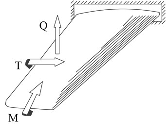
The method of this experiment is able to imitate a great deal of flight conditions and flight postures, including the excursion of the wing's center of pressure, etc. When analyzing the load and strain conditions of the wing, the wing root can be seen as fixed support to the fuselage. The wings are mainly subjected to the bending moment, torque and shear force, both in actual flight and in the simulated conditions of this test. All loading forces applied to the wing can be simplified as a center of pressure load on the aircraft wing. The bending moment, the torque and the shear force on the wing can be considered to be caused by the center of pressure load on the aircraft wing which is simplified by the actual load force on the wing. As shown in Fig. 1, the bending moment (M) is the moment that points to aircraft heading along the rigid axis of the wing; the torque (T) is the moment revolve round the rigid axis of the wing; the shear force (Q) is inner force that the line of action is located at the cross section of the wing.
Fig. 1The bending moment, the torque and the shear force

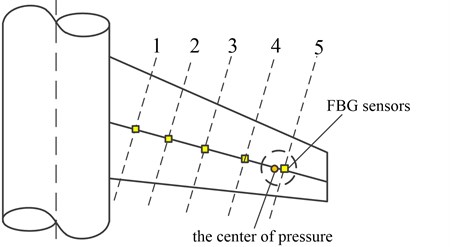
In order to measure the bending moment of the wing, five fiber Bragg grating sensors are distributed on the rigid axle position of the lower wing. The five fiber grating sensors are distributed on a single fiber, and kept away from the stress concentration on the wing. Simultaneously, the last FBG sensor near the wingtips should appear in the circle of the change of the center of pressure according to the analysis of the wing's center of pressure. The five sensors, as shown in Fig. 2, divide the wing into six sections. This paper assumes that each of these “sections”, which are defined herein as the area from one adjacent fiber optic sensor to another, has a consistent structural behavior within each section, but the structural behavior may be different in different sections. For temperature compensation, there is several temperature FBG sensors distributed on the wing. These FBG temperature sensors are distributed at areas where strain can be neglected on the wing, used to correct the influence of temperature on the calculated strain results.
Fig. 2FBG sensors for strain monitoring on the wing

The fiber grating sensors sampling frequency in this experiment is 200 Hz. The center wavelengths of the fiber grating are filtered. The curve of the center wavelength of fiber grating vary with time are obtained, and the wave crest and trough value are taken to study and for strain calculation. The real-time strains at the location of the sensors are calculated by Eq. (5), and the coefficients KT and Kε in this equation are obtained in advance by the calibration test for the optical fiber used in this experiment.
3.2. Correlation between strain and bending moment
Five strains of the cross section are obtained by the five sensors which divided the wing into six sections. In the actual engineering application, the local cross section bending moment has an approximate proportional relationship with the strain of the local cross section:
where Mi is the bending moment of the local cross section i, εi is the strain of the local cross section i, and Ki is the coefficient of proportion relation between bending moment and strain of the local cross section i.
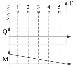
When analyzing the load, bending moment and strain of the wing, the wing root can be considered as fixed support to the fuselage. And the wing is regarded as a cantilever beam structure with a single point of force at the end. As shown in Fig. 3, studying from a one-dimensional state, the shear force on the wing is equal to the constant amount of the force on center of pressure, and the bending moment is a diagonal line.
Fig. 3Simplified wing model

On account of the bending moment is a diagonal line, there is a proportional relationship between the bending moments of each cross section and the strains of each cross section:
=(x+a1):(x+a2):(x+a3):(x+a4):x,
where x is the distance between the center of pressure and the location of the fifth sensor, and ai is the distance between the location of ith sensor and the location of the fifth sensor.
Only with the strain data of five sensors, it is not able to get the solution of Eq. (7). One of the conditions in this experiment is the excursion of the wing's center of pressure. When the wing’s center of pressure moves proximately to the location of the fifth sensor, the strain measured at fifth sensor is close to 0, and the formula of the proportional relationship between the bending moments of each cross section and the strains of each cross section transforms into:
For the distance between the location of ith sensor and the location of the fifth sensor ai is known, the coefficients Ki can be solved by the Eq. (8). The result of the solution can be expressed as:
Accordingly, the real-time bending moments of the wing are able to be calculated by the strain measured in real time by Eq. (9).
4. Conclusions
In this paper, the experiment was performed in full-scale fatigue test of an aircraft subjected to specific loading and severe environment. The FBG sensors were distributed on the span wise direction of the wing. The real-time strains collected by the sensors are calculated by the variation of the Bragg wavelengths. The load on the wing is simplified to a force acting on the wing’s center of pressure and the wing is regarded as a cantilever beam structure with a single point of force at the end. A relationship matrix K is established by the proportional relationship between the bending moments of each cross section and the strains of each cross section. Strain data in variety locations are used for the numerical calculation, when the wing's center of pressure moves proximately to the location of the fifth sensor.
References
-
Doebling S. W., Farrar C. R., Prime M. B., Shevitz D. W. Damage Identification and Health Monitoring of Structural and Mechanical Systems from Changes in Their Vibration Characteristics: a Literature Review. Los Alamos National Laboratory Report LA-13070-MS, Los Alamos National Laboratory, Los Alamos, NM 87545, 1996.
-
Nader Okasha M., Dan Frangopol M., Duygu Saydam Reliability analysis and damage detection in high-speed naval craft based on structural health monit. Structural Health Monitoring, Vol. 10, Issue 4, 2011, p. 361-379.
-
Yang Bin, Xuan Fu Zhen, Xiang Yanxun Lamb wave-based structural health monitoring on composite bolted joints under tensile load. Materials, Vol. 10, Issue 6, 2017, p. 652.
-
Staszewski W., Boller C., Tomlinson G. R. Health Monitoring of Aerospace Structures: Smart Sensor Technologies and Signal Processing. Wiley, New York, 2003, p. 1-73.
-
Kim Jin Hyuk, Park Yurim, Kim Yoon Young, Shrestha Pratik, Kim Chun Gon Aircraft health and usage monitoring system for in-flight strain measurement of a wing structure. Smart Materials and Structures, Vo. 24, Issue 10, 2015, p. 105003.
-
Grattan K. T. V. Optical fibre sensors and measurement systems. Proceedings of the 15th Imeko World Congress, Vienna Proceedings, Vol. 25, 2000, p. 195-200.
-
Leung C. K. Y. Fiber optic sensors in concrete: the future? NDT&E International, Vol. 34, 2001, p. 85-94.
-
Handawi Khalil Al, Vahdati Nader, Rostron Paul, Lawand Lydia, Shiryayev Oleg Strain based FBG sensor for real-time corrosion rate monitoring in pre-stressed structures. Sensors and Actuators B: Chemical, Vol. 236, 2016, p. 276-285.
-
Sante Raffaella Di Fibre optic sensors for structural health monitoring of aircraft composite structures. Recent Advances and Applications, Sensors, Vol. 15, Issue 8, 2015, p. 18666-18713.
-
Mousumi Majumder, Tarun Kumar Gangopadhyay, Ashim Kumar Chakraborty, Kamal Dasgupta, Bhattacharya D. K. Fibre Bragg gratings in structural health monitoring – present status and applications. Sensors and Actuators A: Physical, Vol. 147, Issue 1, 2008, p. 150-164.
-
Lokos William A., Olney Candida D. Strain-gage loads calibration testing of the active aero elastic wing f/a-18 airplane. AIAA 2002-2926.

