Abstract
Carbon fiber drive shafts are nonlinear structures of complex character, difficult to establish “a’priori”. The only way of modeling is to make identification based on the results of measurements of real objects. In previous works, Authors describe the process of building a mathematical model of such a system and its identification on the basis of experimental results but for only one reduced mass. On this basis, however, it is not possible to write a two-mass model because the identified function describing the resilience characteristics also ‘covers’ errors of other model parameters. So, Authors in this paper showed the process of selection of right model which can show the effects of passing shaft’s critical speeds by system with two reduced masses. In conclusion, future model identification procedure for nonlinear phenomena was announced.
1. Introduction
It is well known that carbon fiber constructions are very flexible, anisotropic and have nonlinear characteristics of elasticity. For this type of material, Hook's law is not satisfied either. The carbon composite is also not essentially a material in the present meaning of the word, since it acquires its full properties only after shaping the finished product. It is therefore difficult, on the basis of classical strength tests usually performed on a flat beam sample, to conclude on the properties of an actual structure operating under complex load conditions. These features make the use of traditional calculation methods not applicable here. Such a design would usually be too large in relation to the requirements and often it may not be able to meet the basic strength requirements.
Because of the lack of dynamic computation methods, Authors in some previous works [1-5] proposed methodology of building mathematical model based on some experimental results. The results obtained in these works made it possible to develop the accurate model of the shaft, that simulates critical acceleration and deceleration. The model was based on several simplifications. Firstly, the shaft was reduced to a single rotating disc and massless shaft. Secondly, we take into account only transverse vibrations. Such simplifications allow to reduce the model to the system with one degree of freedom with linear damping and vibration forced by harmonic force.
Authors decided to use obtained experimentally the elasticity characteristic and damping coefficient for identification and model tuning. This also simplified the measurements, since only the displacement of the shaft centre with reduced mass was considered.
Authors decided to use as the identification base, the movement of the centre of the shaft. The displacement measurements were carried out by the laser displacement sensor. Experiments were performed for various velocities of accelerations and decelerations of the shaft. Obtained results [3-5] indicated very strong dependence on acceleration velocity (deceleration) of the shaft.
Equation of motion model obtained in this way will take a form:
where the elasticity force FS is represented by the dependence:
2. Proposition of model based on two rotating disks and massless shaft
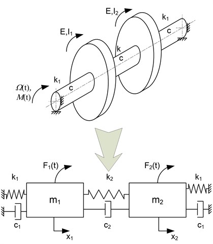
The reduced mass model illustrated in point 1, allows a very good and rapid identification of low complexity systems. Unfortunately, it does not allow generalization of inference and transfer of results to more complicated systems [6-8]. For this purpose, consider a model with two masses concentrated. The fundamental difference with one mass model is that we can’t use it to identify the elasticity characteristics obtained experimentally. Assuming a symmetric mass distribution, we must accept at least 2 different stiffness values. This cause that the previously adopted “correction” taking into account the influence of velocity on the elasticity characteristics can’t be applied in the same way. In order to obtain correct and physically interpretable model identification, we must assume the existence of at least two independent correction factors. A separate problem is damping in the system. Assume in analogy to one mass system its linear character, assume initial value obtained experimentally and equally for all three sections of the shaft.
Fig. 1The model of carbon fiber shaft – two disks with massless beam

The model shown at (Fig. 1) is a classic model with two degrees of freedom. The introduction of non-linear characteristics of the elasticity dependent in addition to the velocity of vibration requires considerable attention and diligence in the analysis of the results, so that it can be identified with experimental results. An additional impediment to the task is that the force exerted by F1 and F2 is in fact the force-induced harmonics dependent on the rotation frequency of the Ω.
Therefore, consider the identification of the model shown in Figure 1 in three steps. Equations of motion model written in accordance with d’Alembert principle will be as follows:
m2¨x2+c1˙x2+c2(˙x2-˙x1)+k1x2+k2(x2-x1)=F2(t).
In the first step, we assume that the force inducing F1 and F2= 0 and damping c1=c2=0, we obtain free vibrations for which the predicted solution of the system Eq. (3) will be given by the expression:
x2=A21sin(ω1t+φ1)+A22sin(ω2t+φ2),
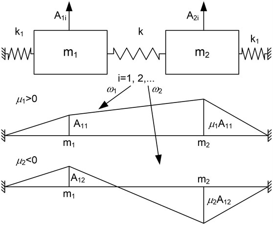
where the natural frequencies ω1 and ω2 depend solely on the mass and elasticity distribution and the amplitude ratios will be formulated by the following expressions:
A22A12=k1+k2-m1ω22k2=k2k2+k1-m2ω22=μ2.
The values of μ1 and μ2 will determine the forms of vibration.
Fig. 2Forms of natural vibrations

In the second stage let’s consider the effect of system damping. Assuming equal damping for all segments of the shaft, the solution of the equations of motion will assume the form:
x2=C21e-h1tsin(ω*1t+φ1)+C22e-h2tsin(ω*2t+φ2).
As we can see, we see the damping exponents h1 and h2, the frequency of self-damped vibrations as well as the forms of their own vibrations.
The most complicated model, we will consider in the third stage. In addition to damping, it will include the harmonic force F(t)=Fcos(ωt)=Feiωt:
m2¨x2+2c˙x2-c˙x1+k1x2+k2(x2-x1)=F2cos(ωt)=F2eiωt.
Considering the forced vibrations established (after the free vibration has been extinguished due to the activation of the force), we can assume:
-m2ω2x2+ciω(x2-x1)+ciωx2+k1(x2-x1)+k2x2=F2.
3. Conclusions
As you can see from these brief reflections, choosing the right model for identification is not a trivial matter. It is safe to say that at the mathematical modelling stage, it is difficult to answer the question of which model will best pass the test for identification with experimental results. Currently, the authors are at the stage of performing an active experiment and choosing the right model. The effect of these works will be presented in the future articles.
References
-
Dąbrowski Z., Deuszkiewicz P. Designing of high-speed machine shafts of carbon composites with highly nonlinear characteristics. Key Engineering Materials, Vol. 490, 2012, p. 76-82.
-
Deuszkiewicz P., Pankiewicz J., Dziurdź J., Zawisza M. Modeling of powertrain system dynamic behavior with torsional vibration damper, advanced materials research. Advanced Materials Research, Vol. 1036, 2014, p. 586-591.
-
Dąbrowski Z., Deuszkiewicz P. Nonlinear dynamic model of a carbon-epoxy composite structure, Proceedings of 20th International Congress on Sound and Vibration, 2013.
-
Dąbrowski Z., Deuszkiewicz P. Dynamic model of carbon fiber drive shaft. Solid State Phenomena, Vol. 236, 2015, p. 39-52.
-
Deuszkiewicz P. Critical states of carbon fiber drive shafts. Vibroengineering Procedia, Vol. 3, 2014, p. 165-168.
-
Chiliński B., Pakowski R. Analysis of bending and torsional vibrations of rotors with using perturbation methods. 3rd Polish Congress of Mechanics and 21st International Conference on Computer Methods in Mechanics, Vol. 1, Issue 2, 2015, p. 15-17.
-
Grządziela A. Modeling of propeller shaft dynamics at pulse load. Polish Maritime Researches, Vol. 15, Issue 4, 2008, p. 52-58.
-
Grządziela A. Diagnosis of naval gas turbine rotors with the use of vibroacoustic parameters. Polish Maritime Researches, Vol. 7, Issue 3, 2000, p. 14-17.

