Abstract
Actually, the side bearings of constant contact cabs are installed on freight cars of new design railroad gage of 1520 mm. Parameters of side bearing elastic elements have significant effect on dynamic behavior of the car and traffic safety. The article is devoted to comparison of side bearing of standard (rigid, shim) design body and bearings of constant contact by means of computer modeling.
1. Introduction
For over than 50 years freight cars are operated on model 18-100 bogies which initially have been designed under an axial load of 22.5 t. During this time the axial load has been increased to 23.5 t without making any serious modifications into bogie design [1, 2]. However, since increasing in axle loading the mode of bogies became different from rated mode and number of constructive shortcomings which caused emergence of significant forces in a zone of contact of a wheel and a rail, to intensive and uneven abrading of friction pairs, insufficiently damped fluctuations of the car in the movement [3, 4]. Within the last 10 years many research and design organizations solve this issue by creation of freight cars of new generation with the raised axial loads and the increased between-repairs run [5-8]. The main constructive decisions applied by the car-building industry during creation of bogies of new generation it is use of elastic adapters between an axle box and a sidewall, elastic and tight roller of side bearing of constant contact, bilinear spring suspension, etc. The present article considers the influence of existence of side bearing of constant contact on forces arising between nodes of the bogie and a body on traffic safety of the freight car and therefore on abrading in wheel and rail system [9-11]. It is known a few works devoted to impact assessment of side bearings of constant contact and their parameters on dynamics of the freight car [12-15]. Therefore, it should be noted the fact that the simulation model of side bearings of constant contact considering its constructional features is described for the first time.
2. Materials and methods
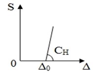
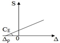
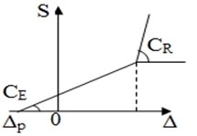
Key parameters of elastic side bearings of constant contact are vertical and longitudinal rigidity of an elastic element [1]. Nowadays on the railroads of Russia and the CIS countries three main types of side bearing of a carriage body differing in the characteristic of an elastic component in the vertical have gained distribution:
1) Standard rigid with a gap (bogies of model 18-100) – (Fig. 1(a));
2) Elastic with a preliminary inhaling (bogies of model 18-194, 26V.502, etc.) – (Fig. 1(b));
3) Elastic rolling with a preliminary inhaling (bogies of model 18-578, etc.) - (Fig. 1(c)).
wherein – power; – deformation; – preload; – gap; , , – rigidity of standard bearer of the elastic element and roller of elastic bearer relevantly.
The simulation techniques used in this article have been prepared by the “Universal Mechanism” program complex [2]. The elastic component of a damper of a side bearing is carried out in the form of the nonlinear power characteristic with preliminary loading (Fig. 2).
Fig. 1Specifications of elastic components of side bearings in vertical
a)
b)
c)
Fig. 2Description of elastic component of the bearer
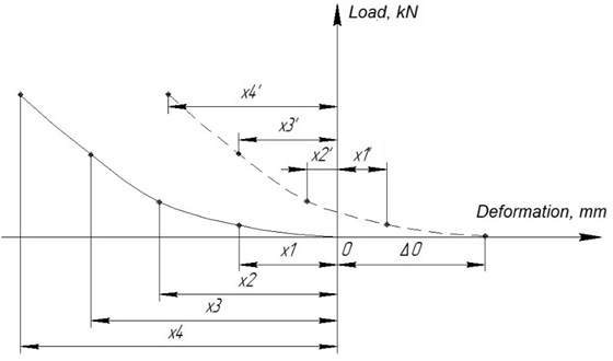
In Fig. 2 the following legends are adopted: – preload pressure deformation; – point’s value on abscissa; . The element works only when 0 < < < < .
The abscissa characteristic difference, indicated in Fig. 1 and in Fig. 2 appeared due to power component work direction.
In this paper the power characteristic of a damper of carriage body side bearing of model 18-578 described in [3] is accepted.
The dissipative component of a power element is set in the form of expression:
where – the element length on timepoint; – speed of change of element length; – deformation of preliminary loading; – element length by the beginning of modeling; – dissipation coefficient; heavi – Hevisayd’s function which is given below:
For example, if 94 of mm and 22 mm, then at ≤ 116 of mm of fluctuation fade, otherwise expression Eq. (1) will be equal to zero, that is the element works only for compression. Also, it should be noted that expressions in brackets in Eq. (1) are dimensionless and are intended for control of work of dissipative element.
Along with vertical rigidity of an elastic element the behavior of the car has significant effect on dynamic longitudinal rigidity of a side bearing of a body of constant contact [4].
We will consider the settlement scheme of definition of the resistance moment to turn arising in a thrust bearing and side bearing in the course of turn of the bogie relatively to carriage body (Fig. 3).
Fig. 3Design circuit of definition of the resistance moment to turn arising in mounting center of the body on the bogie
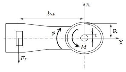
The total moment of resistance arising between basic surfaces of a body and the bogie in the course of turn of a truck bolster relevantly to the body, in the absence of transfer of a body, identical deformation of elastic elements of side bearing and lack of longitudinal gaps between a cap and the case of a support, can be determined by expression:
where – friction coefficient between center block and a thrust bearing; – internal radius of a thrust bearing basic surface, ; R – external radius of a thrust bearing basic surface, ; – vertical rigidity of an elastic element of a side bearing, H/m; – vertical deformation of an elastic element of the support, m; – sliding friction coefficient between a cap of a side bearing and a side bearer of the body; – weight of a body, ; – distance from the center of a thrust bearing to a side bearing, .
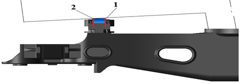
We will consider the scheme of emergence of friction forces between a cap of bearer and reciprocal part of bearer on a body in the presence of a gap between a cap and the case of a support (Fig. 4).
Fig. 4Design of power influencing on the cap of side bearing; 1 – cap of side bearing; 2 – body of supports; 3 – elastic element
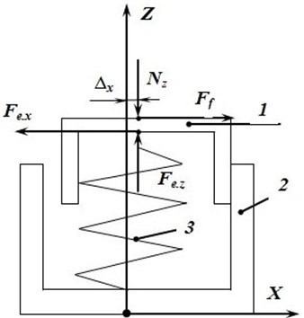
From the Fig. 4 it is obvious that in order of joint movement of the cap of support and the body (at 0 < ), it is necessary to execute the following:
where – coefficient of friction of coupling between a cap of a side bearing and a side bearer of a body; – horizontal rigidity of an elastic element of a side bearing, H/m; – horizontal deformation of an elastic element of the support, m.
If conditions Eq. (4) aren’t satisfied, then support cap shift concerning the bearer of body doesn't occur. At the same time, instead of friction forces between a cap of a support and bearer body, resistance to turn is shown by the elastic force caused by horizontal deformation of an elastic element of the side bearing [5]. In this case, the total moment of resistance arising in the course of turn of a truck bolster is defined by expression:
From comparison of the Eq. (3) and Eq. (5) it is obvious that in case of non-satisfaction of conditions, Eq. (4), the total moment of resistance to rotation shall diminish to value:
At the same time, it is obvious that to turn of expression Eq. (6) to zero it is needed zero expression equality in brackets that allows receiving expression for the minimum horizontal rigidity of an elastic element of a side bearing:
It is obvious from formula analysis Eq. (7) that the exception of change of the moment of resistance to turn of truck bolster within enough small values requires rather great value of horizontal rigidity [6].
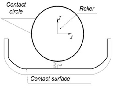
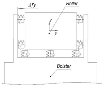
Contact interaction of a roller with insert and the corpus is realized by means of contact elements a circle surface which imitates swings of one body on the second and a point plane (Fig. 5(a)). The gap is provided in the cross plane between the body of the bearer and a roller (Fig. 5(b)).
Fig. 5The scheme of contact interaction of the roller with an insert and the bearer body
a)
b)
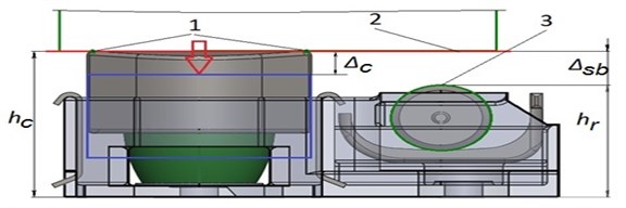
The distance in a free state from the level of reciprocal part of bearer to the basic plane of the bearer body is equal to 146 mm, and the distance of is equal to 116 mm. In position under the body the elastic element is deformed and sinks at a size which in size is equal to a pretightness Eq. (1). When ≥ 30 mm, the gap between a roller and reciprocal part of a cap becomes isolated and occurs contact interaction (Fig. 6). This power interaction has been simulated by two separate contact planes for each body (a cap and a roller) modeling communication of a roller and a cap with a body. These planes are independent from each other [7, 8]. To support these two planes at one level in mathematical model identifiers and are used. The gap between a roller and bearer reciprocal part of cab underframe depends on the size of abrading of the bearer of cab underframe. As 30 mm in a free state, the gap under loading is equal . For example, if 22 mm, then deformation of a damper makes 22 mm and therefore 8 mm.
Fig. 6The scheme of contact interaction of bearer elements and body in the vertical plane, where 1 – contact points on a cap; 2 – the contact plane on the bearer of cab underframe; 3 – contact circle
3. Simulation results
Modeling consisted of two stages:
– modeling of angular fluctuations of the body on truck bolster for the purpose of an assessment of forces, the arising places of body contact and truck bolster;
– modeling the movement of the freight car on sites of a way with direct and curve macrogeometry.
Static fluctuations were set by angular fluctuations of a half of a body as solid body, in the form of harmonic functions of angular movements around axes of coordinates of and (Fig. 7):
Fig. 7Scheme of annexing of angular fluctuations to the body
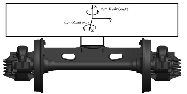
It should be noted that the vertical axis passing through the body center of gravity – a body, when modeling coincided with an axis of center pivot and the truck bolster has been rigidly fixed, that is we ignore fluctuations of truck bolster on springs [9, 10].
When modeling to the analysis the following dependences were plunged:
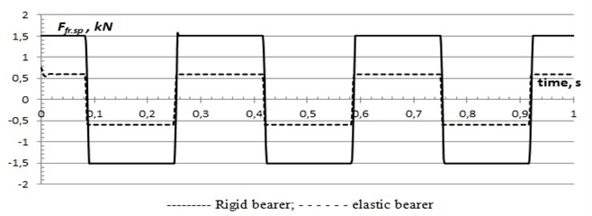
– friction forces on center bowl from time (separately for rigid (standard) and elastic bearer);
– vertical reactions of in contact of a cap of bearer of constant contact, a standard bearer and roller with a body from vertical movement of a cap and in time [11-12].
The parameters of bearer of constant contact used in the course of modeling are presented in Table 1.
Table 1Parameters of constant contact bearer
No. | Parameter | Measurement unit | Meaning |
1 | Compressive stiffness of the elastic element (in vertical) | МN/m | 0.91 |
2 | Static deflection of elastic element at positioning under the carriage body (deformation of preload pressure) | mm | 22 |
3 | Preliminary loading (starting stitch) | kN | 20 |
4 | Fraction coefficient between bearer points (steel on steel) | – | 0.3 |
5 | Gap between roller and cap at positioning under the carriage body | mm | 8 |
6 | Lateral rigidity of elastic element | МN/m | 5.00 |
From Fig. 8 it is visible that friction forces in contact points on a thrust bearing for bearer of constant contact are about 67 % lower, than for rigid bearer. It proves the fact that use of bearer of constant contact leads to reduction of the friction forces moments in knot a center pivot-thrust bearing, therefore, to reduction of their abrading due to transfer of part of the moment on the bearer [13].
Fig. 8Friction forces in contact points on thrust bearing in time
The size of normal reaction in rigid bearer also much more, than at elastic bearer of constant contact. It, first of all, is caused by existence of a gap in rigid bearer that leads to emergence of blow between them (see Fig. 9).
Fig. 9Normal reactions in contact of bearers of the bogie and carriage body (ωrx= 9.42 rad/sec, Rz= 0.01 rad)

Also, it is necessary to pay attention that normal reaction to surfaces of a cap of the bearer without gaps begins with the size of preliminary loading.
As it was already noted above, this mathematical model allows to model rollers the elastic rolly bearer. To estimate influence of a roller on forces arising between a body and a truck bolster modeling at fluctuations of a body of rather vertical and longitudinal axes at the same time was made, at 18.84 rad/sec; 0.02 rad.
From Fig. 9. it is visible that force of reaction to circles 2 arises owing to short circuit of a gap between a roller and a cap and it is more, than on a circle 1 as at turn of a body of rather longitudinal axis after the choice of a gap in 8 mm, the bearer on the carriage body will adjoin to a circle 2 in the beginning, and then already to a circle of 1 (Fig. 10, 11).
Fig. 10Dependence of the reaction on the roller from the turn angle ωrx=ωrz= 18.84 rad/sec, Rx=Rz= 0.02 rad

Fig. 11Arrangement of contact circles
Simulating of the movement of the freight car with rigid bearer and bearer of constant contact on direct and curve sites of a way was the following stage.
As the estimated indicators angles of rotation of a truck bolster of the first in the direction of the bogie and the moment of friction forces between a cap of a bearer of constant contact and bearers on the carriage body have been accepted. If angles of rotation of a truck bolster show intensity of wagging of bogies of empty cars in direct sites of a way, then the friction moments between a cap of an elastic bearer and bearers on a body exert impact on the efforts arising between a wheel and a rail at the movement of the loaded car on a curve [14].
As the twisting movement is most actively shown at high speeds of the movement, modeling was carried out at a speed of 120 km/h. The results of modeling are presented in the form of angles of rotation of truck bolster of the bogie in Fig. 12-14:
Fig. 12Turning angles of truck bolster of the bogie with standard bearer
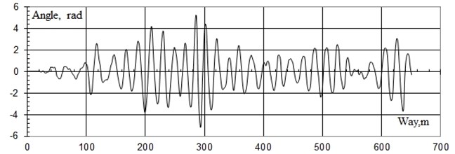
Fig. 13Turning angles of truck bolster of bogies with elastic bearers
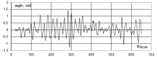
Fig. 14Turning angles of truck bolster of the bogie with elastic and rolling bearers
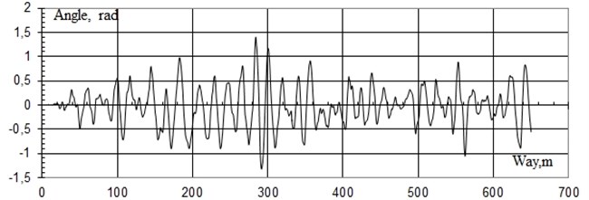
Apparently from oscillograms the angles of wagging of truck bolsters of bogies from bearer of constant contact at a speed of 120 km/h is 3.5 times less than bogies with standard bearer.
4. Conclusions
It, first of all, is caused by the fact that in mathematical models longitudinal degree of freedom and longitudinal rigidity of an elastic element of a bearer are considered. It is defining in decrease in angles of bogies wagging under an empty body. For the purpose of an assessment of influence of existence of a roller for the friction moments between a cap of an elastic bearer and bearer on a body computer modeling of the movement of the loaded car on curve 350 m with an eminence of 130 mm has been carried out [15].
So, in Fig. 15-16 oscillograms of the moments of friction forces arising between caps of external bearer and a body in the longitudinal direction which interfere with turn of bogies under a body are shown.
Fig. 15Oscillogram of the friction power moment on the left cap of the bearer the first on bogie movement
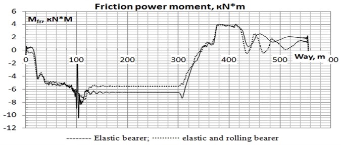
Fig. 16Oscillogram of the friction power moment on the left cap of the bearer the second on bogie movement
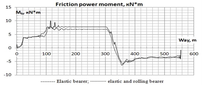
From oscillograms of the moments of friction forces arising between a body and caps of bolster in the longitudinal direction for a site without roughness’s it is visible that existence of the roller mechanism promotes reduction of the moments of friction forces interfering turn of bogies under a body and by that reduce probability of a running on of wheels on rails. As a result of simulation modeling it is revealed that elastic bearer of constant contact promotes reduction of the twisting movement of freight cars in the empty mode, due to longitudinal rigidity of an elastic element of a side bearing. Existence of the roller established parallel to an elastic bearer allows reducing the moment of friction forces between a body and caps of the bearer interfering turn of bogies under a body and by that reduce probability of a descent of wheel couples from rails in transitional curves. The imitating model developed by authors of article elastic and the elastic rolling of bearer of constant contact can be used for an assessment of influence of technical parameters of bearer (vertical and longitudinal rigidity of an elastic element, gaps between the case, a cap and a roller, properties of contact elements, etc.) on dynamics of the car, traffic safety and abrading in system a wheel-rail.
References
-
Musayev J., Zhauyt A., Nurymov Y., Mamatova G., Adilkhanov Y., Alizhan A., Chigambaev T. The influence of operational factors on the contact-fatigue effect of couple of wheel-rail friction in curves of small radius. Vibroengineering Procedia, Vol. 8, 2016, p. 263-268.
-
Musayev J., Zhauyt A., Sagatbek M., Matikhan N., Kaliyev Y., Naurushev B. Seismic resistance of horizontal underground openings in anisotropic rocks. Vibroengineering Procedia, Vol. 8, 2016, p. 231-236.
-
Abilkaiyr Z., Musayev J., Kaiym T., Alpeisov A., Alimbetov A., Zhauyt A. The interaction of the freight car and way taking into account deformation of assembled rails and sleepers. Vibroengineering Procedia, Vol. 8, 2016, p. 269-274.
-
Janat Musayev, Algazy Zhauyt Analysis of disturbing influence of traffic load on soil body. Advances in Materials Science and Engineering, Vol. 2015, 2015, p. 1-7.
-
El-Rashidy R. A., Grant-Muller S. M. An assessment method for highway network vulnerability. Journal of Transport Geography, Vol. 34, 2014, p. 34-43.
-
Erath A., Löchl Axhausen M. K. W. Graph-Theoretical analysis of the swiss road and railway networks over time. Networks and Spatial Economics, Vol. 9, Issue 3, 2009, p. 379-400.
-
Hoshiya M., Yamamoto K. Redundancy index of lifeline systems. Journal of Engineering Mechanics, Vol. 128, Issue 9, 2002, p. 961-968.
-
Hoshiya M., Yamamoto K., Hno H. Redundancy index of lifelines for mitigation measures against seismic risk. Probabilistic Engineering Mechanics, Vol. 19, Issue 3, 2004, p. 205-210.
-
Jenelius E. Network structure and travel patterns: explaining the geographical disparities of road network vulnerability. Journal of Transport Geography, Vol. 17, Issue 3, 2009, p. 234-244.
-
Kanno, Y., Ben-Haim, Y. Redundancy and robustness, or when is redundancy redundant. Journal of Structural Engineering, Vol. 137, Issue 9, 2011, p. 935-945.
-
Koç Y., Warnier M., Kooij R. E., Brazier F. M. T. An entropy-based metric to quantify the robustness of power grids against cascading failures. Safety Science, Vol. 59, 2003, p. 126-134.
-
Lhomme S., Serre D., Diab Y., Laganier R. Analyzing resilience of urban networks: a preliminary step towards more flood resilient cities. Natural Hazards and Earth System Sciences, Vol. 13, Issue 2, 2013, p. 221-230.
-
Miao X., Xi B., Guan M., Tang Y. H. Route entropy based capacity reliability assessment and application in multi-objective satisfactory optimization of logistics network. Scientific Research and Essays, Vol. 6, Issue 16, 2011, p. 3335-3343.
-
Vladimir Solonenko, Narzankul Mahmetova, Janat Musayev, Mikhail Kvashnin, Algazy Zhauyt, Toty Buzauova Modeling of dynamic characteristics of freight car with optimized parameters of wedge-type shock absorber. Journal of Vibroengineering, Vol. 19, Issue 2, 2017, p. 1197-1213.
-
Solonenko V., Mahmetova N., Musayev J., Kvashnin M., Alpeisov A., Zhauyt A. Some aspects of the experimental assessment of dynamic behavior of the railway track. Journal of Theoretical and Applied Mechanics, Vol. 55, Issue 2, 2017, p. 421-432.
