Abstract
Pounding and unseating have been repeatedly observed during severe earthquakes. Residual displacement between adjacent components may have already existed after the mainshock and it will get further destroyed with series of aftershocks. The uniform drift cable-sliding modular expansion joints (UDCMEJ) are constructed by connecting the supporting bars and the fuse boxes with elastic cables avoiding the excessive relative displacement between girders. The seismic analysis of bridges with UDCMEJ under the excitation of seismic sequence is conducted on a continuous beam bridge and a probabilistic assessment is introduced in this study. Conclusions are drawn from comparing fragility curves with and without UDCMEJ. It reveals that the UDCMEJ can avoid pounding between girders and the relative displacement is limited to cables’ free movement. With the contribution of the expansion joints, all of the girders work together and get a balance between displacement and force causing decreased damage probability.
1. Introduction
The seismic isolation theory is widely used in recent bridge designs for ductility aseismic methods will introduce damages into bridge systems though this can be repaired after earthquake. The aseismic bearing is one of the most common aseismic devices in bridges and buildings [1, 2]. And some isolate bearings are even used in the isolated nuclear power plants system [3]. The steel bearing, sliding leader bearing, sliding isolated bearing and even the leader rubber bearing are usually used as aseismic devices [4, 5]. The isolated bearing separates the decks from piers causing limited inertia force transferred to the piers. The flexibile bridge system corresponds with relative decreased PGA on the ground motion spectrum along with the changed dynamic characteristic. Then the seismic response of the bridge system is further decreased. However, to get a balance between displacement and force, the isolated bridge usually performs with large relative displacement between girders. Moreover, the large relative displacement would induce pounding damage. And it is well recognized that the out-of-phase vibration of adjacent segments caused either by various dynamic characteristics, such as natural periods, or spatially seismic input variances, will lead to strong collision [6-8]. For instance, in Mexico City earthquake, pounding was observed in damage structures with a percentage of 40 % and 15 % of them collapsed due to the pounding [9].
And in light of recent strong seismic events, several aftershocks were followed by strong main shocks (e.g. the 1994 Northridge earthquake; the 2008 Wenchuan earthquake; the 2012 Emilia earthquake) and the damaged structures were shown to be more vulnerable to severe damage (The Luanhe Bridge collapsed with the excitation of aftershocks 15 hours after the mainshock). The residual displacement between girders may have already existed after the main shock and this would increase the vulnerability of pounding damage when excited by aftershocks. However, pounding and unseating is expected to be avoided. Additionally, almost all seismic specifications for highway bridges including Caltrans, AASHTO and specifications of Japan and China have mentioned to restrict relative displacement between girders by using cable-sliding devices. Therefore, various types of restrainers, dampers and other restraint devices have been provided to mitigate damages caused by excessive relative displacement [10].
SMA restrainers, FRP restrainers, glass, carbon and hybrid restrainers are often used to mitigate the pounding and unseating damages [11, 12]. Recently, investigators have focused on the application of the modular expansion joints to mitigate relative displacement-induced damages at bridge joints caused by seismic movements [13, 14]. However, large expansion clearance would induce relative large component and systematic fragility though with decreased pounding force. Additionally, the traditional restrainers couldn’t limit the relative displacement when the girders get closer. To achieve the ideal restraint effect, the restraint cable must be used by combining with other restrainers. However, the new uniform drift cable-sliding modular expansion joints provided by Yuan could limit the relative displace when adjacent girders get closer or further away [15]. The UDCMEJ is constructed by connecting the supporting bars and fuse boxes with elastic cables at both ends of the support bars. The uniform drift mechanical system is used to adjust the clearance between longitudinal beams of modular expansion joints. Thus, a single elastic cable gets the effect on preventing both pounding and unseating.
Seismic fragility function, which defines the probability of physical damage as a function of ground motion intensity parameter provides a probabilistic assessment method from developing vulnerability information for bridges. This could be used to assess the effect of UDCMEJ in mitigating pounding. Nowadays, seismic fragility has become a critical and integrated part of the performance-based earthquake engineering (PBEE) framework. To integrate aftershocks into risk analysis, DesRoches developed a framework for aftershock fragility assessment of damaged structures that can account for the damage accumulation [16]. In this paper, the fragility analysis of bridges equipped with UDCMEJ under excitation of seismic sequence is conducted on a continuous girder bridge. And the restraint effect on mitigation pounding damage is assessed with the probability method.
2. Uniform drift cable-sliding modular expansion joints (UDCMEJ): structures and restoring force model
The traditional modular expansion joints (MEJ) contain several central beams and two edge beams joined by the bridge girder. Seals cover the gap between the beams and ensure the water tightness of the joints. The traffic load on the center beams is transmitted to the supporting bar via yokes. Sliding spring, bearing yokes and fuse box are also the integral components of the MEJ system.
Fig. 1Basic components of the UDCMEJ

Based on the conventional design, the UDCMEJ is constructed by connecting the supporting bar and fuse box at both ends with an elastic cable as shown in Fig. 1. The cable is designed with free movement length, so that the excessive relative displacement between adjacent girders could be restrained without impacting its functional service. And the limitation effect for different bridge structure design can be realised by adjusting the free movement length. The uniform drift mechanical is used to adjust the clearance between adjacent beams and thus the movement mechanical system and force-transmitting system is separated. The uniform drift mechanical system has great meaning on ensuring the beams moving uniformly while having little effect on the seismic response. Moreover, the expansion joints have little function on limiting the seismic relative displacement [13], therefore, the stiffness of the expansion joints is ignored in this paper.
However, the elastic cables make an important impact on the seismic response of the bridge. Fig. 2 illustrates that when earthquake occurs, the relative displacement between girders is limited through the connective cables whether they get closer or further away. So, the UDCEMJ have the functions of preventing pounding and unseating. The UDCMEJ is the latest design and there isn’t any engineer application case. Additionally, the anchorage of the elastic cable is assumed to be reliable. So, the relationship between displacement and restoring force of the UDCMEJ can be expressed as follows (Fig. 2(d)):
∆d is the relative displacement between adjacent girders, and ∆g is the free movement of the UDCMEJ for which the cable is not work while f is the restore force. Parameter k1 is the stiffness provided by expansion joints and is taken as 0 in this paper. And k is the stiffness provided by the restraint cable. Parameter k is relevant to the cable section and it is calculated by the following equation:
where n is the number of cables, A is the sectional area of per cable, E is the elastic modulus of the cable, and L is the length of each cable.
Fig. 2Working mechanism of UDCMEJ
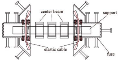
a) Normal state of a UDCMEJ system
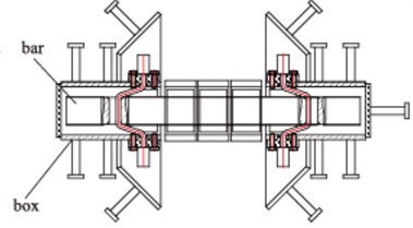
b) When the adjacent girders get close
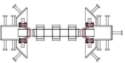
c) When the adjacent girders far away
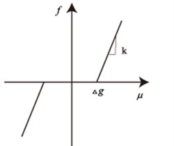
d) Force and displacement relationship of UDCMEJ
3. Bridge system characteristic
A particular triple continuous girder (30 m × 3 + 36 + 50 + 36 + 30 m × 3) bridge is introduced to conduct the nonlinear time history analysis of bridges equipped with UDCMEJ excited by the seismic sequence. The superstructure is standard T-shaped beam segment with depth of 2.3 m and width 11.9 m. All the bridge piers are with hollow rectangular cross section shown in Fig. 3(c). In this paper, the influence of the abutment is not considered. Generally, the expansion joints clearance incorporates the requirements of temperature change and normal operation. In this study, the expansion joints clearance is 12 cm which means that pounding won’t occur for relative displacement within 12 cm. In this paper, the freedom movement of the expansion joints for the isolated bridge is 8 cm indicating that when the relative displacement between girders is larger than 8 cm the cable will work.
Fig. 3Generic geometry of the multi-span continuous girder bridge and force-displacement relationship for the bearings

a) The layout of the continuous frame bridge

b) The distribution diagram of bearings
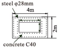
c) Pier
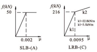
d) Force and displacement relationship of bearings
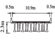
e) Deck
The finite element model is constructed on Opensees platform. Bridge girders are modeled using linear elastic beam-column elements as these components are expected to respond within elastic during earthquakes. The beam-column elements are aligned along the central line of bridge decks. The relative movement between girders and piers is simulated by the bilinear force-displacement relationship shown in Fig. 3(d). Discretized fiber sections applied to beam-column elements are used for the columns, and the pile foundations are modeled with simplified linear translational and rotational springs-the six spring stiff element. The stiffness of the spring is calculated by the “m” method. The UDCMEJ is simulated by composed multi-linear element with the relationship between deformations and restore force shown in Fig. 2(d).
In order to analyze the seismic response of the isolated bridges with UDCMEJ considering the seismic sequence the following cases are established respectively:
Case 1: The Bridge equipped UDCMEJ excited by mainshock only. This is described as UDCMEJ-mainshock.
Case 2: The Bridge equipped with traditional MEJ excited by mainshock only. This is described as As-built -mainshock.
Case 3: The Bridge equipped with UDCMEJ excited by seismic sequence. This is described as UDCMEJ-sequence.
Case 4: The Bridge equipped with traditional MEJ excited by seismic sequence. This is described as As-built -sequence.
3.1. Selection of the seismic sequence
Earthquakes are usually a part of a sequence of ground motions which can be defined as foreshocks, main shocks and aftershocks. The artificial seismic sequence could significantly overestimate median peak and residual drift demands as well as the record-to-record variability [17]. Therefore, in order to study the influence of aftershocks, as-recorded seismic sequences including the mainshock and at least one aftershock are required for performing nonlinear time history dynamic analysis. In this study, seismic sequences are selected according to the following criteria: (a) magnitude of mainshock equals to or greater than 5.5 and major aftershock equals to or greater than 4.0; (b) accelerograms are recorded by stations which are located in free field or low buildings; (c) the ratios between peak ground accelerations of major aftershock and mainshock equal to or greater than 0.7. Under these criteria, 20 as-recorded mainshock–aftershock seismic sequences, which have been recorded during a short period of time, by the same station, in the same direction, and almost at the same fault distance, are selected from the strong motion databases of the COSMOS and PEER.
Each of the aforementioned sequential ground motions has been separated into a single ground motion where 50 s gap is applied between two consecutive seismic events. This duration is deemed to be sufficient for bridges ceasing vibration caused by the mainshock. A particular seismic sequence is shown in Fig. 4. And the corresponding response shows the residual displacement between adjacent girders has already existed after the mainshock. And the restraint effect is clearly shown in Fig. 4.
Fig. 4A particular seismic sequence and corresponding responses

a)

b)
3.2. Methodology
This study aimed to assess the failure modes by fragility curves for the critical bridge components, including the bearing and column. The fragility curves reflect the probability of meeting or exceeding the damage state. Methodology for the case study is stated in details below.
The variability of seismic response under the range of ground motions is assessed by a set of different ground motion records. And the variability of the modeling parameters is not considered. The probabilistic seismic demand models at a certain ground motion intensity (peak ground acceleration, PGA, in this study) is assumed as lognormal distributions. The means and standard deviation for a certain PGA is calculated by the sequence of incremental dynamic analysis. Many equations are used to generate the fragility curves. However, Ivrahim and El-Shami simplified it as follows:
where D – damage, Φ – standard normal cumulative distribution, μ – mean, σ – standard deviation of the PGA natural logarithm.
3.3. Capacity and demand estimate
The structural damage under earthquake is described in terms of a damage index (DI). As a function of the structural responses, the DI for various components requires specific limit state values. Given that the isolated bridge piers would be avoided from damage, the vulnerability of isolated pier is ignored in this study. The bearing displacement and the relative displacement between girders are monitored to measure bridge damage. The suggested limit state are referred to Pang [18]. For the difficulty in defining extensive damage index, only the slight and moderate damage index is defined. The limit states corresponding to HAZUS damage state levels are listed in Table 1.
Table 1definitions of the damage states and corresponding DI criteria
Component | DI | Slight | Moderate |
Displacement of LRB | s (m) | η>0.05 | η>0.15 |
Displacement of SLB | η (m) | η>0.10 | η>0.25 |
Relative displacement between girders | d (m) | η>0.12 |
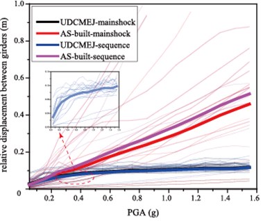
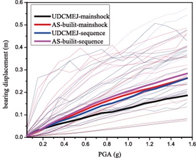
Fig. 5Examples of the IDA cures for: a) relative displacement between girders, b) the displacement of bearing P52-1
a)
b)
Fig. 5 shows the IDA curves of relative displacement between girders and the bearing displacement of P52-1. The mean values for the incremental dynamic analysis is highlighted. It indicates that the aftershock could increase the seismic response. Taking PGA 0.1 g as an example, the relative displacement between girders is about 27 cm with the excitation of mainshock while it arrives at around 32 cm when encounters with seismic sequence. And the UDCMEJ gets great effect on restraining the relative displacement between adjacent girders, more specifically, the relative displacement is limited to the free movement length of the UDCMEJ which is 8 cm in this study. With the increasing of the seismic intensity which is indicated by PGA, the differences in the relative displacement between the two cases change with different seismic intensity. Additionally, the bearing displacement shows the same trend. The bearing displacement decreases when excited by earthquakes after constructed with UDCMEJ.
3.4. Fragility analysis
The fragility curves for a certain damage state can be calculated from Eq. (3). In this paper, it is assumed that once the relative displacement between girders reaches the initial clearance pounding will occur (12 cm in this paper). The pounding catastrophe is assessed using the fragility method in this paper. Fig. 6 shows the probability of pounding which is indicated by relative displacement between adjacent girders. And it shows that the pounding probability increases for the sake of aftershocks.
Fig. 6The probability of pounding between adjacent girders
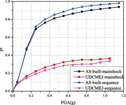
However, the restraint expansion joints could decrease the pounding probability perfectly. As shown in Fig. 6, taking PGA 0.4 g as an example, the probability of pounding is 23 % and 27 % with the excitation of mainshock and seismic sequence respectively when constructed with UDCMEJ, while the probability reaches 80 % and 82 % when equipped with the traditional expansion joints.
Fig. 7 shows the fragility curves of bearing displacement for slight and moderate damage state. It shows that aftershock increase the vulnerability of bridge for a particular damage state and bridge class. It is illustrated that the damage probability of bearing increases with the influence of aftershocks. And it is interesting to find that the bearing vulnerability is decreased with the work of UDCMEJ, specifically, differences between bridges with and without the new expansion joints is apparent within the range from 0.1 g to 0.7 g. The restraint expansion joints connect the adjacent girders when the relative displacement exceeds the freedom movements. The dynamic characteristic will change when the elastic cable works. Therefore, the relative movement of adjacent girders is counteracted or balanced without pounding causing decreased inertial force to the piers.
Fig. 7The fragility curves of bearing
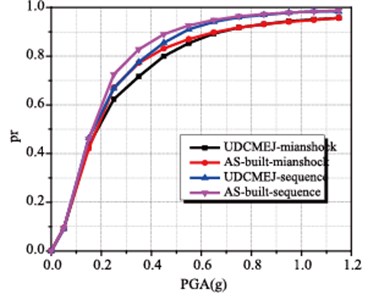
a) The fragility curves of bearing P41-1-slight
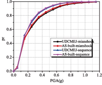
b) The fragility curves of bearing P52-1-slight
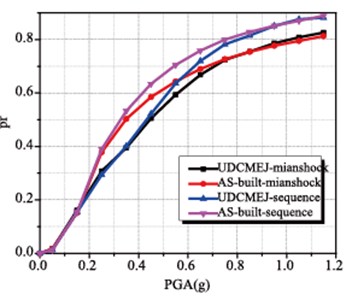
c) The fragility curves of bearing P41-1-moderate
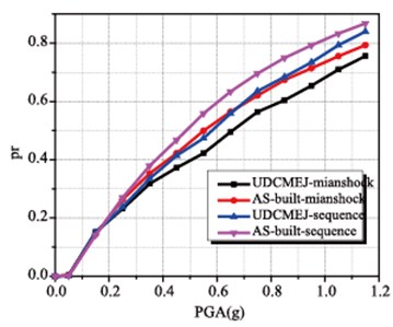
d) The fragility curves of bearing P52-1-moderate
4. Conclusions
This work presents a new pounding and unseating prevention device the uniform drift cable sliding modular expansion joints which is constructed by connecting the supporting bars and fuse boxes with elastic cables. And the seismic sequence is introduced to assess the effect on pounding mitigating and unseating prevention. A case study is conducted on a particular triple continuous girder bridge with the incremental dynamic analysis. The following conclusions are deduced from the analytical results presented herein.
1) It is clear that the residual displacement between girders has already existed after the mainshock.
2) Aftershock could increase the seismic response for both the relative displacement between girders and the bearing displacement.
3) The UDCMEJ could well restraint the relative displacement between adjacent girders decreasing pounding vulnerability.
4) Bearing displacement is decreased with the effect of UDCMEJ which mitigates the probability of unseating in some extent.
References
-
Yuan Wancheng, Binbin Wang, Pakchiu Cheung, et al. Seismic performance of cable-sliding friction bearing system for isolated bridges. Earthquake Engineering and Engineering Vibration, Vol. 11, Issue 2, 2012, p. 173-183.
-
Bin Yan, Du Xiu Li, Han Qiang, et al. Principle of Sliding-Restricting and Its Application in Seismic Design of a Continuous Beam Bridge. ASCE, 2014, p. 481-488.
-
Labbé Pierre EDF experience on design and construction of nuclear power plants on seismic isolation systems. Technical Innovation in Nuclear Civil Engineering, 2013, p. 29-31.
-
Raja Hussain, et al. Incorporation of rubber-steel bearing isolation in multi-storey building. Journal of Civil Engineering and Management, Vol. 22, Issue 4, 2016, p. 584-584.
-
Alam Shahria M., Bhuiyan Rahman M. A., Billah Muntasir A. H. M. Seismic fragility assessment of SMA-bar restrained multi-span continuous highway bridge isolated by different laminated rubber bearings in medium to strong seismic risk zones. Bulletin of Earthquake Engineering, Vol. 10, Issue 6, 2012, p. 1885-1909.
-
Huo Yili, Jian Zhang Effects of pounding and skewness on seismic responses of typical multispan highway bridges using the fragility function method. Journal of Bridge Engineering, Vol. 18, Issue 6, 2012, p. 499-515.
-
Jankowski Robert Non-linear FEM analysis of pounding-involved response of buildings under non-uniform earthquake excitation. Engineering Structures, Vol. 37, 2012, p. 99-105.
-
Luo Zhi, Li Jianzhong, Yan Bo Research on the control of displacement between pier and girder of continuous rigid frame bridge with high pier in mountain area. Engineering Mechanics, Vol. 33, Issue 1, 2016, p. 148-156.
-
Won Jeong Hun, Ho Seong Mha, Sang Hyo Kim Effects of the earthquake-induced pounding upon pier motions in the multi-span simply supported steel girder bridge. Engineering Structures, Vol. 93, 2015, p. 1-12.
-
Bipin Shrestha, Hao Hong, Bi Kaiming Devices for protecting bridge superstructure from pounding and unseating damages: an overview. Structure and Infrastructure Engineering, Vol. 12, Issue 3, 2016, p. 1-18.
-
Rahman Bhuiyan M. A., Alam Shahria M. Seismic vulnerability assessment of a multi-span continuous highway bridge fitted with shape memory alloy bars and laminated rubber bearings. Earthquake Spectra, Vol. 28, Issue 4, 2012, p. 1379-1404.
-
Saiid M., Rita Johnson, Manos Maragakis E. Development, shake table testing, and design of FRP seismic restrainers. Journal of Bridge Engineering, Vol. 11, Issue 4, 2006, p. 499-506.
-
Mccarthy Emily, Wright Timothy, Padgett Jamie E., et al. Development of an experimentally validated analytical model for modular bridge expansion joint behavior. Journal of Bridge Engineering, Vol. 19, Issue 2, 2013, p. 235-244.
-
Chouw Nawawi, Hong Hao Seismic design of bridge structures with allowance for large relative girder movements to avoid pounding. Bulletin of the New Zealand Society for Earthquake Engineering, Vol. 42, Issue 2, 2009, p. 75-85.
-
Gao Kang, Wancheng Yuan, Sasa Cao, et al. Seismic performance of cable-sliding modular expansion joints subject to near-fault ground motion. Latin American Journal of Solids and Structures, Vol. 12, Issue 7, 2015, p. 1397-1414.
-
Han R., Li Y. J., Van De Lindt Loss estimation of reinforced concrete buildings considering aftershock hazards. Structures Congress, 2015.
-
García Ruiz Jorge, Negrete Manriquez Juan C. Evaluation of drift demands in existing steel frames under as-recorded far-field and near-fault mainshock–aftershock seismic sequences. Engineering Structures, Vol. 33, Issue 2, 2011, p. 621-634.
-
Pang Y. T., Kai W., Yuan W. C., et al. Effects of dynamic fluid-structure interaction on seismic response of multi-span deep water bridges using fragility function method. Advances in Structural Engineering, Vol. 18, Issue 4, 2015, p. 525-541.
About this article
This research was supported by the National Key Technology Research and Development of the Ministry of Science and Technology of China under Grant No. 2015BAK17B04; the Ministry of Science and Technology of China under Grant No. SLDRCE14-B-14; the National Natural Science Foundation of China under Grant Nos. 51478339 and 51778471; and the Science Technology Plan of JiangXi Province under Grant No. 20151BBG70064.
