Abstract
In this paper, the Isogeometric Analysis (IGA) is applied to make the modal analysis for 3D gun barrel. The geometry of IGA is modeled by None-Uniform Rational B-Splines (NURBS) which is exact and smooth even at the coarsest mesh level. The first 9 natural frequencies were calculated respectively by IGA and traditional finite element method (ABAQUS), and compared with the test results. The maximum relative error between numerical value and experimental value is less than 3.6 % which verifies the feasibility of numerical model. Six different refinement schemes were analyzed to compare the computational accuracy and efficiency of IGA and ABAQUS. To achieve the credible results, the CPU time of ABAQUS is more than twice of IGA. On this basis, the IGA method is used for the structural shape optimization of gun barrel. The first natural frequency is increased by 6.96 % and the barrel mass is reduced by 4.9 %.
1. Introduction
During the launching process of artillery, the barrel will vibrate violently under a series of complex load excitations including the powder gas pressure, the contact force of projectile and the recoil resistance, etc. The vibration directly affects the firing dispersion extent and even results in devastating consequences. Therefore, it is very necessary to study the vibration characteristics of barrel. The modal analysis is used to determine the vibration characteristics, natural frequencies and mode shapes, and it is also the basis of further dynamic analysis. The common method to get the modal parameters of barrel includes the experiment modal analysis and finite element modal analysis. However, it is difficult to conduct the experiment modal analysis restricted by the experimental conditions. Hence, the virtual modal analysis becomes the most commonly used method in the design and optimization process.
At present, most of the virtual modal analysis is based on the traditional FEA whose application platform is very mature (such as ABAQUS, ANSYS, etc.). Su Z. [1] updated the finite element model of a gun barrel based on modal test which significantly improved the accuracy of model. The structural characteristics of barrel was reflected more precisely, and it provided a more realistic model for the analysis of firing accuracy. Dou Z. [2] studied the tube dynamics feature based on FEM. The first 50 modes were calculated by finite element method and compared with the experimental results. In the aspect of barrel optimization, Liu Q. [3] optimized the barrel of a mortar based on ANSYS, the barrel weight is reduced by 13 % after simulation optimization and the light weight design of the barrel is effective and reliable. Fang J. [4] present a multi-objective optimization of barrel combining Neural Networks and the genetic algorithms based on ANSYS. It provided an improved optimization effect and a higher efficiency.
The above work is generally based on the traditional finite element method which has two insurmountable defects: the finite element mesh is the approximation of geometry, the design model (CAD) and analysis model (CAE) are separate. To get a relatively accurate barrel model, we have to refine the FE mesh by very small size which greatly increases the system DOF. Correspondingly, it will cost more computation. On the other hand, the separation between CAD and CAE distinctly results in difficulties in structural optimization. The interactive process of design model and analysis model will occur several times and even a dozen times. The re-meshing process which turns the design model to analysis model will take a lot of time and effort.
In order to obtain a more accurate model and higher computational efficiency, the IGA [5-7] method is introduced to the modal analysis of barrel. NURBS can exactly describe the circular geometry even at coarse mesh level [8], and it takes obvious advantage in building the model because the barrel is constituted by a series of cylinders. The DOF of NURBS model is much less than that of FE model, thus, the computation scale of IGA will be much smaller than traditional FEA. Furthermore, the uniform of design model and analysis model in IGA will provide many advantages in the optimization process [9-17].
This paper is organized as follows. Section 2 introduces the modeling process of gun barrel. Section 3 presents the modal analysis based on IGA, the results of modal analysis are compared between IGA, ABAQUS and experiment and the computing time are compared then. Section 4 shows the structural optimization based on genetic algorithm and Section 5 concludes the work.
2. NURBS model of barrel
For the details and extensive references about NURBS, the reader is referred to Piegl and Tiller and Cottrell et al. [18-22]. Here we present the modeling process of the three-dimension barrel based on NURBS.
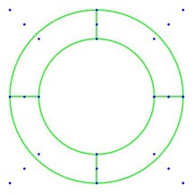
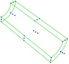
Fig. 1Diagram of circle and a quarter of cylinder
a)
b)
As the barrel is composed by several cylinders and the cylinder is stretched by circle, we should build a circle first of all. Fig. 1(a) shows a two-dimension NURBS circle, the blue points are the control points and the green lines are the control mesh (all the orders of NURBS geometry in this paper is 2). If we stretch the circle along a certain direction by a certain length, a cylinder is formed. For the sake of intuition, Fig. 1(b) gives a quarter of the cylinder.
The gun barrel is reduced to five parts, Fig. 2 shows the diagram of barrel size and the different section line represents the different NURBS patch. The NURBS control mesh (drawn by Tecplot) of barrel is shown as Fig. 3 and the detailed parameters are present in Table 1.
Fig. 2Diagram of barrel size

Fig. 3Diagram of barrel control mesh
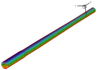
Table 1Parameters of barrel
Parameter | Value | Parameter | Value |
L2 | 170 mm | D4 | 282 mm |
L3 | 1680 mm | D5 | 259 mm |
L5 | 1625 mm | Young’s modules (E) | 2.1E5 MPa |
D2 | 335 mm | Poisson’s ratio (υ) | 0.3 |
D3 | 322 mm | Density (ρ) | 7.85E-9 Ton/mm3 |
3. The modal analysis of barrel based on IGA
The Isogeometric modal analysis of 2D problem is present in my previous work [23] and the 3D problem is given in this section. The computation efficiency and accuracy are verified by comparing with standard FEA (ABAQUS).
3.1. Isogeometric modal analysis
The differential equation for free vibration can be written by:
where M is the global mass matrix, K is the global stiffness matrix and U is the global displacement vector.
By assuming U=eiωtˉU, Eq. (1) can be rewritten as:
To solve the equation, it becomes the eigenvalue problem:
where ˉU is the associated displacement vector and the solution of Eq. (3) are the natural frequencies.
By using the NURBS basis functions, the approximated displacement functions for volume can be present as:
where Ni,p(u1), Nj,q(u2) and Nk,r(u3) are the normalized B-Splines basis functions whose degree are p1, p2 and p3, wi,j,k are the associated weights of control points, ncp is the number of control points, RA and uA are the NURBS basis function and displacement corresponding to the control point A respectively.
As the discretization of displacement is given above, we can start from the following fundamental equation:
where ε is the element strain, L is the differential operation, B is the strain-displacement matrix, ue is the element displacement vector.
According to the principle of isoparametric transformation, the matrix B gives:
where J is the Jacobian mapping physical and parametric domains, (xi, yi, zi) are the coordinates of control points.
By implementing the virtual displacement method with the existence of body forces b and traction forces T, we can write:
Substituting the Eq. (6) and the constitutive equation, σ=Dε, in Eq. (9), the stiffness matrix can be obtained as:
as well as the mass matrix:
where D is the elastic matrix, ρ is the material density.
3.2. Numerical example
To demonstrate the performance of modal analysis based on IGA, ABAQUS is selected to compare the simulation results between IGA and FEA. The analysis model is built in Section 2 and the first 9 natural frequencies are calculated. In the finite element method, the calculation begins to converge after the mesh refinement increase to a certain level. We assume that the results which achieve the convergence are the receivable simulation values. Table 2 and Table 3 shows the simulation results with six different refinement level, respectively (the unit of all the frequencies is Hz).
Table 2The first 9 natural frequencies using IGA
Mode | DOF | |||||
1620 | 5760 | 17280 | 31104 | 58752 | 72567 | |
1 | 20.21 | 20.79 | 21.12 | 21.13 | 21.13 | 21.13 |
2 | 20.21 | 20.79 | 21.12 | 21.13 | 21.13 | 21.13 |
3 | 54.56 | 55.85 | 58.17 | 58.17 | 58.18 | 58.19 |
4 | 54.56 | 55.85 | 58.17 | 58.17 | 58.18 | 58.19 |
5 | 100.67 | 105.03 | 112.09 | 112.11 | 112.14 | 112.15 |
6 | 100.67 | 105.03 | 112.09 | 112.11 | 112.14 | 112.15 |
7 | 155.17 | 168.02 | 183.81 | 183.85 | 183.86 | 183.88 |
8 | 155.17 | 168.02 | 183.81 | 183.85 | 183.86 | 183.88 |
9 | 174.04 | 185.05 | 206.82 | 206.97 | 207.01 | 207.2 |
Table 3The first 9 natural frequencies using ABAQUS
Mode | DOF | |||||
21708 | 28944 | 123264 | 308988 | 412128 | 837648 | |
1 | 20.626 | 21.039 | 21.198 | 21.31 | 21.345 | 21.353 |
2 | 20.626 | 21.039 | 21.198 | 21.31 | 21.345 | 21.353 |
3 | 56.545 | 57.840 | 58.122 | 58.436 | 58.532 | 58.55 |
4 | 56.545 | 57.840 | 58.122 | 58.436 | 58.532 | 58.55 |
5 | 108.67 | 111.04 | 111.65 | 112.23 | 112.42 | 112.45 |
6 | 108.67 | 111.04 | 111.65 | 112.23 | 112.42 | 112.45 |
7 | 178.14 | 181.62 | 182.82 | 183.77 | 184.06 | 184.12 |
8 | 178.14 | 181.62 | 182.82 | 183.77 | 184.06 | 184.12 |
9 | 200.2 | 203.24 | 205.81 | 207.17 | 207.51 | 207.70 |
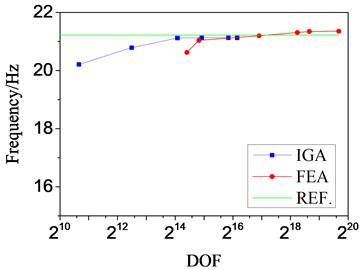
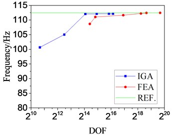
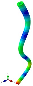
Both results confirm the inference: the calculations approach the reference value along with the increasing of DOF. For better comparison, we choose the 1st natural frequency and 5th natural frequency to illustrate the tendency, as shown in Fig. 4. Because of the large span of the abscissa, we use exponential index for x axis. The mode shapes of 5th are compared in Fig. 5.
Fig. 4Curves of frequency-DOF
a) Mode 1
b) Mode 5
For the 1st natural frequency, IGA reach the reference value when the DOF achieve about 214 and FEA comes near the reference value when the DOF achieve a little less than 216. The convergence gap is more obvious for the 5th natural frequency, it differs by more than four orders of magnitude. Thus, we can give a conclusion that the DOF needed in traditional FEA is at least two orders of magnitude more than that in IGA to reach the credible result.
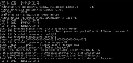
Table 5 gives the computing parameters and Table 6 compares the CPU time of modal analysis. We can find that the CPU time used in IGA is more than twice less than that of FEA which verifies the calculation efficiency of IGA. Fig. 6 gives the running process of IGA using FORTRAN language.
Table 5The computing parameters of FEA and IGA
Parameters | FEA | IGA |
CPU | Intel(R) Core(TM) i7-4700HQ @ 2.40GHz 2.40 GHz | |
RAM | 8.00 GB | |
Operating system | Windows 10 Professional Edition | |
Modes | First 20 | |
Model DOF | 308988 | 16848 |
Computing platform | ABAQUS | IVF (Intel Visual Fortran) |
Solver | Solver in ABAQUS | MKL (DFEAST_SCSRGV) |
Table 6The CPU time of different element type
Element type | CPU Time/s | |
1 | 2 | |
C3D8 | 55.92 | 56.62 |
C3D8R | 52.83 | 53.57 |
NURBS | 17.97 | 18.12 |
Fig. 5Comparisons of mode shapes

a) 5th mode shape of IGA
b) 5th mode shape of FEA
Fig. 6The running process of FORTRAN
3.3. Experimental results
Fig. 7 gives the physical map of barrel and Fig. 8 shows the test platform. The modal test software is PULSE 7753 of B&K, the data acquisition system is 3050-A-060 of B&K, the acceleration sensor is 8702B50 of KISTLER, the force harmer is 9728A20000 of KISTLER, the modal parameter identification software is PULSE Reflex of B&K.
Fig. 7The physical map of barrel

Table 7 gives the comparison of numerical results and experimental results. We can find that the the maximum relative error between numerical value and experimental value is less than 3.6 % which verifies the feasibility of numerical model.
Fig. 8The test platform
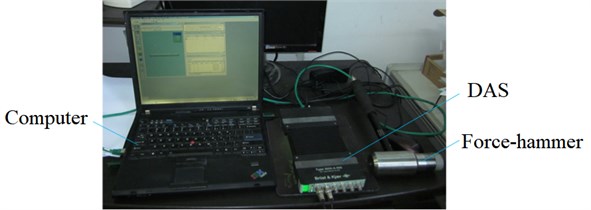
Table 7The comparison of numerical results and experimental results
Mode | Experimental results | ABAQUS | IGA |
1 | 20.59 | 21.345 | 21.13 |
2 | 20.59 | 21.345 | 21.13 |
3 | 57.26 | 58.532 | 58.18 |
4 | 57.26 | 58.532 | 58.18 |
5 | 110.37 | 112.42 | 112.14 |
6 | 110.37 | 112.42 | 112.14 |
7 | 183.57 | 184.06 | 183.86 |
8 | 183.57 | 184.06 | 183.86 |
9 | 206.89 | 207.51 | 207.01 |
4. The structural optimization based on genetic algorithm
4.1. Optimization model
There are three elements in the optimization design: design variable, constraint condition and objective function. Referring to the model built in Section 2, the design variables are given as follow:
where xi are corresponding to the following equation:
The optimization objective in this work is improving the 1th natural frequency and decrease the barrel mass. The objective function is:
where f1(X) is the 1st natural frequency of barrel, f2(X) is the mass of barrel, wi are the weight coefficents.
We set the seven design variables which are allowed to float up and down by ten percent as the constrain conditions. The boundary of the design variables are shown in Table 8. Meanwhile, the barrel should meet the strength requirements at the most dangerous section:
and the geometric dimension should satisfy the following relationships:
In order to ensure the closure of the barrel structure size, the total length L and the length of small slope L4 and L6 remain unchanged. The L7 gives:
By integrating the above three elements, the mathematical model of this problem can be obtained by:
where X are the design variables, x_i is the minimum design dimension, ˉxi is the maximum design dimension, σm is the stress of the most dangerous section, [σ] is the yield stress of material, ˉf1(X) and ˉf2(X) are the 1st natural frequency and the mass before optimization.
The optimization algorithm selected in this paper is genetic algorithm. There are many advantages such as: rapid random search capability, robustness, potential parallelism and expandability etc. It is widely used in various fields and the algorithm process is very mature [24-27]. Here we don’t need to introduce the algorithm but give the parameters shown in Table 9.
Table 8The space of design variables
Design variable | Initial value | Lower bound | Upper bound |
x1 / mm | 335 | 318 | 350 |
x2 / mm | 322 | 306 | 342 |
x3 / mm | 282 | 268 | 308 |
x4 / mm | 259 | 246 | 270 |
x5 / mm | 170 | 153 | 187 |
x6 / mm | 1680 | 1596 | 1800 |
x7 / mm | 1625 | 1462 | 1745 |
Table 9Parameters of genetic algorithm
Parameter | Value |
Population size | 50 |
Maximum generation | 80 |
Crossover rate | 0.8 |
Mutation rate | 0.1 |
4.2. Optimization results and analysis
The dimension parameters and optimization objectives before/after optimization are shown in Table 10. We find that the thickness at D2 and D3 should be increased and the other two radiuses can be appropriately reduced. For the length, L2, L3 and L4 have increased in varying degrees and the length near the muzzle, L7, whose thickness is smaller has been cut down a lot. It means that the thick parts are beneficial to strengthen the barrel stiffness.
The 1st natural frequency is enhanced from 21.345 Hz to 22.83 Hz which increased by 6.96 % and the mass of barrel is changed from 2.465 tons to 2.343 tone which reduced by 4.9 %. The results meet the optimization objective and prove the feasibility of the proposed method.
Fig. 9 shows the interactive process between CAD and CAE of traditional FEA. As the CAD model and FE mesh are separate, we have to transform the model in every optimization step. The design model and analysis model in IGA are both NURBS which unifies the interactive process as shown in Fig. 10. It brings great convenience and makes the optimization process very concise.
Table 10Dimension parameters and optimization objectives before/after optimization
Parameters | Initial | Optimization results |
x1 / mm | 335 | 339.7 |
x2 / mm | 322 | 329.1 |
x3 / mm | 282 | 279.4 |
x4 / mm | 259 | 249.0 |
x5 / mm | 170 | 180.6 |
x6 / mm | 1680 | 1707.7 |
x7 / mm | 1625 | 1672.3 |
1st natural frequency / Hz | 21.345 | 22.83 |
Mass / ton | 2.465 | 2.343 |
Fig. 9The interactive process between CAD and CAE of traditional FEA
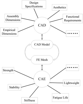
Fig. 10The interactive process between CAD and CAE of IGA

5. Conclusions
In this paper, we have applied the Isogeometric analysis method to the modal analysis and optimization of gun barrel. The motivation of this research is based on two facts:
1) The barrel is consisting of circle structure which is perfectly fit for NURBS. It not only provides smooth boundary, but also gives accuracy description even at the coarse mesh level. The model based on NURBS lead to a smaller scale of DOF and the computation efficiency can be improved accordingly.
2) The separation between CAD and CAE in traditional FEA has seriously affected the computation efficiency of optimization work. However, the uniformity of design model and analysis model in IGA provides a good solution for this problem.
The modeling process of three-dimension barrel based on NURBS is present. The modal analysis with six different level of mesh refinements are compared between IGA and traditional FEA (ABAQUS). The accuracy of the numerical model is verified by comparing with the experimental results. The CPU time of the numerical analysis proves the efficiency of Isogeometric Analysis. The optimization based on genetic algorithm is investigated and the obtained results showed the feasibility of the proposed method. The further work would extend this approach to the muzzle disturbance optimization.
References
-
Su Z., Xu D., Xue J., et al. Finite-element updating for a gun barrel based on modal test. Journal of Vibration and Shock, Vol. 31, Issue 24, 2012, p. 54-59.
-
Dou Z., Chen Y., Li Y. Research of tube dynamics feature based on FEM. Machine Design and Research, Vol. 29, Issue 3, 2013, p. 126-130.
-
Liu Q., Zhso H., Xie J. Analysis of barrel structural optimization for a mortar. Journal of Measurement Science and Instrumentation, Vol. 3, 2015, p. 258-263.
-
Zhou W., Fang J. Application of the modified response surface method to reliability optimization design of gun barrel. Mechanical Science and Technology for Aerospace Engineering, Vol. 2, 2016, p. 176-181.
-
Hughes T. J. R., Cottrell J. A., Bazilevs Y. Isogeometric analysis: CAD, finite elements, NURBS, exact geometry and mesh refinement. Computer Methods in Applied Mechanics and Engineering, Vol. 194, Issue 39, 2005, p. 4135-4195.
-
Bazilevs Y., Calo V. M., Cottrell J. A., et al. Isogeometric analysis using T-spline. Computer Methods in Applied Mechanics and Engineering, Vol. 199, Issue 5, 2010, p. 229-263.
-
Hughes T. J. R., Reali A., Sangalli G. Efficient quadrature for NURBS-based isogeometric analysis. Computer Methods in Applied Mechanics and Engineering, Vol. 199, 2010, p. 301-313.
-
Cottrell J. A., Hughes T. J. R., Bazilevs Y. Isogeometric Analysis: Toward Integration of CAD and FEA. Wiley Publishing, 2009.
-
Wall W. A., Frenzel M. A., Cyron C. Isogeometric structural shape optimization. Computer Methods in Applied Mechanics and Engineering, Vol. 197, Issues 33-40, 2008, p. 2976-2988.
-
Qian X. Full analytical sensitivities in NURBS based isogeometric shape optimization. Computer Methods in Applied Mechanics and Engineering, Vol. 199, Issues 29-32, 2010, p. 2059-2071.
-
Cho S., Ha S. H. Isogeometric shape design optimization: exact geometry and enhanced sensitivity. Structural and Multidisciplinary Optimization, Vol. 38, Issue 1, 2009, p. 53-70.
-
Nagy A. P., Abdalla M. M., Gürdal Z. Isogeometric sizing and shape optimisation of beam structures. Computer Methods in Applied Mechanics and Engineering, Vol. 199, Issues 17-20, 2010, p. 1216-1230.
-
Wang Z. P., Turteltaub S., Abdalla M. Shape optimization and optimal control for transient heat conduction problems using an isogeometric approach. Computers and Structures, Vol. 185, 2017, p. 59-74.
-
Lieu Q. X., Lee J. A multi-resolution approach for multi-material topology optimization based on isogeometric analysis. Computer Methods in Applied Mechanics and Engineering, Vol. 323, 2017, p. 272-302.
-
Li K., Qian X. Isogeometric analysis and shape optimization via boundary integral. Computer-Aided Design, Vol. 43, Issue 11, 2011, p. 1427-1437.
-
Hassani B., Tavakkoli S. M., Moghadam N. Z. Application of isogeometric analysis in structural shape optimization. Scientia Iranica, Vol. 18, Issue 4, 2011, p. 846-852.
-
Manh N. D., Evgrafov A., Gersborg A. R., et al. Isogeometric shape optimization of vibrating membranes. Computer Methods in Applied Mechanics and Engineering, Vol. 200, Issue 13, 2011, p. 1343-1353.
-
Ha S. H., Choi K. K., Cho S. Numerical method for shape optimization using T-spline based isogeometric method. Structural and Multidisciplinary Optimization, Vol. 42, Issue 3, 2010, p. 417-428.
-
Piegl L., Tiller W. The NURBS, Book. Springer Berlin Heidelberg, 1997.
-
Elguedj T., Bazilevs Y., Calo V., et al. B– and F– projection methods for nearly incompressible linear and non-linear elasticity and plasticity using higher-order NURBS elements. Computer Methods in Applied Mechanics and Engineering, Vol. 197, Issue 33, 2008, p. 2732-2762.
-
Cottrell J. A., Hughes T. J. R., Reali A. Studies of refinement and continuity in isogeometric structural analysis. Computer Methods in Applied Mechanics and Engineering, Vol. 196, Issue 41, 2007, p. 4160-4183.
-
Rogers D. F. An Introduction to NURBS: With Historical Perspective. Morgan Kaufmann Publishers Inc. 2001.
-
Sederberg T. W., Cardon D. L., Finnigan G. T., et al. T-spline simplification and local refinement. ACM Transactions on Graphics, Vol. 23, Issue 3, 2004, p. 276-283.
-
Cheng Q., Yang G., Lin C., et al. The modal analysis of disc resonator gyroscope using isogeometric analysis. Journal of Vibroengineering, Vol. 19, Issue 1, 2017, p. 468-476.
-
Goldberg D. E. Genetic algorithms in search, optimization and machine learning. Addison-Wesley Publishing Company, 1990.
-
Davis L. Handbook of Genetic Algorithms. Handbook of Genetic Algorithms, 1991.
-
Austin S. An introduction to genetic algorithms. Artificial Life, Vol. 3, Issue 1, 1996, p. 63-65.
-
Deb K., Pratap A., Agarwal S., et al. A fast and elitist multiobjective genetic algorithm: NSGA-II. IEEE Transactions on Evolutionary Computation, Vol. 6, Issue 2, 2002, p. 182-197.
Cited by
About this article
This work is supported by the program of Natural Science Foundation of China (Grant No. 11172139).

