Abstract
The article describes the mathematical model and the method and results of simulation modeling of the drive of lifting of the downhole motor from the well. The system of differential equations takes into account the elastic properties of a long mechanical line (tubing string), as well as non-linearity: friction, variable elasticity, pressure limitation. Transient and frequency characteristics are obtained.
1. Introduction
In the industry’ drives with a long connecting link highway are widely used.
Such a method of power transfer is used in the processing of deep holes, in the manufacture of power generating systems, as well as in the oil and gas industry (production of downhole motors, well wiring).
Operation of the drive with the long mechanical connecting link is followed by different dynamic phenomena.
These phenomena are largely due to the contact interaction of the executive body (tool) with the object, the length of the connecting line (rod) from the entrance to the output link and their various rotating speeds. It leads to unstable operation of the tool or its breakage and significantly influences quality of the performed works. Generally, the structure of operation of such engine can be explained to Fig. 1.
Fig. 1Scheme of operation of the drive with the long rod: 1 – entrance link; 2 – output link (tool); 3 – long connecting link (rod); 4 – technological object; 5 – surface of contact

In studies [1-3] the features of dynamic phenomena in the processing of internal surfaces of objects by a rotating tool were studied. Further development of the proposed approaches requires the systematization of the analysis of dynamic phenomena using the simulation model and its behavioral algorithm. Such principles fully satisfy the process of simulation based on the development of a system, which includes a mathematical model, the formalization of processes in the given system, the conditions for its functioning, and the formulation of the problem for obtaining the desired solution [4]. The following approach in the solution of this problem is offered.
2. Problem definition
In studies [1-3] the new way of a research of operation of the mechanical drive with the long connecting link is shown. The essence of a method consists in use of system of the equations:
where Ω – speed of movements of bar cross-section, Ω=∂φ/∂t; r – rod radius; G – shear modulus; τ – maximum tangent stress in bar cross-section.
Such an approach makes it possible to establish the relationship between the shear rates of the cross sections of the elementary volume of a straight cylindrical rod and the variation of tangential stresses [3].
Let us formulate the problem of constructing the simulation model as follows. On the basis of the proposed approach, we will investigate the features of the functioning of the leading and output members taking into account:
– contact interaction of an output link with an object;
– remoteness of an object from an entrance (driving) member;
– uneven rotation of members;
– unstable elasticity of the line;
– precession fluctuation of an axis of rotation of a rod of big extent;
– longitudinal fluctuation of a surface of contact of an output member (executive body).
3. Mathematical model of an imitating task
The system of the Eq. (1) allows to connect in an explicit form of speed of the movement and stress in highways. After one-dimensional transformation of Laplace [5] of the Eq. (1) for the matched load the equations have been received [1]:
where θk – operator coefficient of distribution of waves; Mc – resistance moment on the output end of a rod l; Ω1, Ω2 – angular speeds of rotation of entrance (driving) and the output (conducted) end of a rod; τ1, τ2 – the maximum tangent tension in the entrance and output ends of a rod; hk – coefficient of losses on the friction proportional to Ω2; Wp – geometrical polar moment of resistance of bar cross-section; J – flywheel moment of inertia, which is brought to the driven end of the rod; Zk(s) – function characterizing degree of distribution of parameters.
The Eqs. (2), (3) give the chance to calculate frequency characteristics of the drive, i.e. to define reaction of the drive to harmonious change of speed of the movement of the leading link or the moment of resistance.
The function Zk(jω) becomes real for Ω1≡ 0 and the laplacian s=jω, i.e.:
Knowledge of frequency properties, for design engineers, technologists and other specialists is very important. However, it is often necessary to correctly estimate the regularities of the change in the speed of motion and the stresses in time in a real drive that experiences simultaneous sporadic and periodic changes in the resistance force during operation.
Algebraically, we expand the Eq. (2). We obtain:
Fidelity of decomposition is easily checked by the return decision. If, passing to originals of the Eqs. (6), (7) and considering Eq. (5), to execute the return transformation of Laplace of functions:
We will receive that:
Then originals Eqs. (6), (7) it is possible to write down in shape:
With respect to longitudinal oscillations, we write Eqs. (6) and (7) in the form [1]:
where f2 – cross-sectional area of rod near the body of the mass m; c, hn,– coefficients of losses on friction; F – resistance force influencing executive body; l – line length.
Systems of Eqs. (10-13) are similar to the systems describing movement of the drive with the short rod [1]. The difference lies in the presence of the multipliers that depend on the frequency of the disturbing oscillations.
Similar equations describe longitudinal oscillations in mechanical drives [1].
4. Imitating model of the mechanical drive
The imitating model of the mechanical drive developed on the basis of the given equations allows to calculate amplitude-frequency characteristics of the mechanical drive, to determine levels of stress in an output link caused by contact interaction and to reveal zones of steady and unstable operation of the tool.
However, due to the peculiarities of any technological process, it is advisable to develop a simulation model for a specific mechanism. Consider a device for lifting a drilling tool from a well, the scheme of which is shown in Fig. 2(a), 2(b).
This drive contains a screw downhole motor 1 with a bit 2 connected to the output shaft. Above the motor there are heavy-weight drill pipes 3 performing various functions, one of which is to increase the load on the bit.
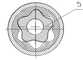
With the drilling rig hook, said parts are connected by means of drill pipes 4. The engine 1 is a gerotor mechanism, the rotor 5 of which is made of steel and has external teeth, and the stator is made with a rubber lining and has internal teeth, and their number is one tooth larger than to the rotor.
Studies of the dynamic features of the operation of the mechanical drive were carried out according to the developed program for a PC.
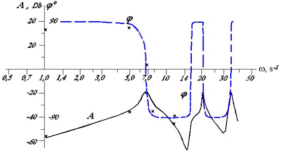
Fig. 2Mechanical drive for lifting the downhole motor from the well: a) – drive layout; b) – cross-section of the engine; c) – logarithmic frequency characteristics: A – amplitude; φ – phase

а)

b)

c)
Initial data: model of bottom-hole engine D1-195; bit (D1-215.9 mm); heavy-weight drill pipes (⌀203×60 mm, L= 20 m); drill string (⌀114×10, LΣ= 1000 m) with drive parameters: m= 34 Ns2/cm; modulus of elasticity – E= 2×10⁵ MPa; coefficient of friction loss – hn= 10 Ns/m.
During modeling, the nonlinear dependence of stresses and deformations of metal pipes (the flow zone in the stress diagram) was taken into account; nonlinear dependence of the coefficient of friction on the speed of the relative motion of friction parts; pressure limitation, etc.
We give the initial system of differential equations used in the numerical solution of the problem and obtained from Eqs. (12-14), in the following form:
The solution was carried out using the Runge-Kutta method [6, 7], the choice of the count step did not exceed the value of the rational error (up to 10 %). The algorithm for the solution is given in [1].
During the numerical simulation of the example under consideration, after a jump in the velocity to υ1= 0.2 m/s at ω= 0, a pause was. At this time, the movement of the lower part of the column of pipes stabilized.
Then, every 10 seconds at υ1= const, different oscillation frequencies of the specified force F were set abruptly step-wise. The results indicated in Fig. 2(c) with the “×” sign, were determined at the stabilization site and were found to be close to the calculation of the frequency characteristics by the Eq. (2).
Thus, cross-checking the method in different ways showed that the described numerical simulation accurately reflects the processes in the real system, and such a mathematical model can be adopted as an imitation model.
In the course of the simulation it was found out that for Z<0 the solution becomes unstable. In the drive with the above mentioned parameters, this occurs in the zones ω= 7.87 – 15.7; 23.6 – 31.5; 39.3 – 47.2 s-1, i.e. stability is lost at frequencies slightly higher than their resonant values.
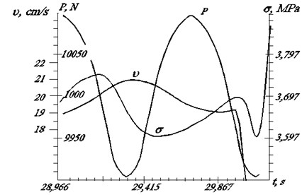
This is probably due to a change in the shape of the oscillations. The stress oscillations σ(t) and the traveling speed υ(t) at such instants of time are shown on the calculated oscillogram (Fig. 3).
Fig. 3Loss of stable operation in the mechanical drive of longitudinal displacement: P – longitudinal force; σ – normal stress in pipes; υ – speed of lifting

It is seen from the graphs that the speed of movement after the change in the value of ω is sharply inhibited, and the stress with a certain delay Δt≈0.1c increases very rapidly.
In the system under consideration, when lifting, the clay solution in the column merges and can rotate the rotor of the screw downhole motor. The frequency of rotation of the latter is Ωp≈zυ2fD/w, where w is the volumetric constant of the motor; Z – number of rotor teeth; fD=πD2D/4 – cross-section of the bit.
Since the rotor is located eccentrically, depending on the lift speed, the value of Ωp, changes, which leads to oscillations of the frictional force. Therefore, the parameter:
where α=lω(ρE-1)0,5=kωl(ρE-1)0,5ν2, changes.
This circumstance gives grounds to believe that at certain lifting speeds a phenomenon equivalent to tacking a tool is possible. For example, if the bit with a downhole motor D1-54 rises from a depth of 1 km, the minimum value of this speed is approximately 1.14 cm/s.
5. Conclusions
With loss of stability in the elastic system, in addition to the described changes, other oscillations arise, for example, torsional and hydraulic, in combination leading to a complicated little studied dynamic processes. The proposed method makes it possible to investigate similar processes in time. In this case, it becomes possible to take into account various nonlinearities. So far, such problems have been solved in the frsequency domain.
References
-
Kondratenko L. A. Calculation of Movement Speed Variations and Stresses in Machine Assemblies and Components. Sputnik, Moscow, 2008.
-
Terechov V. M., Kondratenko L. A., Mironova L. I. Some dynamic features of interaction the cutting part of the gun drill with the detail. Journal of Engineering and Automation Problems, Vol. 4, 2016, p. 78-84.
-
Kondratenko L. A., Terekhov V. M., Mironova L. I. About one method of research torsional vibrations of the core and his application in technologies of mechanical engineering. Journal of Engineering and Automation Problems, Vol. 1, 2017, p. 133-137.
-
Mironova L. I. Computer Technologies in Solving Problems in the Theory of Elasticity. Monograph, Palmarium Academic Publishing, Germany, 2017, p. 188.
-
Ivanov V. A., Chemodanov B. K., Medvedev V. S. Mathematical Foundations of the Theory of Automatic Regulation. High School, Moscow, 1971.
-
Butcher J. C. Numerical Methods for Ordinary Differential Equations. John Wiley and Sons, New York, 2008.
-
Iserles A. A First Course in the Numerical Analysis of Differential Equations. Cambridge University Press, Cambridge, 1996.
