Abstract
The effects on deployment accuracy of joint clearances and forces acting on the deployable mechanism are investigated. “A virtual massless link” is used to describe the joint clearance of the mechanism in the free state. Aiming at the following problems of multi-loop linkages mechanical system such as loop constraints coupling and complicated topology structure, the geometric relationships and the deploying error equations of deployable mechanism are provided based on Denavit-Hartenberg matrix by splitting multi-loop linkage into 3 single-loop linkages. In addition, with consideration of forces, “a virtual massless rope” is used instead of “virtual massless link” to describe the joint clearance for avoiding the extra singularities. And the criterion of mechanism in stable configuration is obtained by weighting coefficient method on the basis of minimum potential principle. The solving procedure of deploying error equations in the state of forces constrained is presented by combining Monte-Carlo method with genetic algorithm, it is an effective solution for the nonlinear objective function with multiple constraints and strong coupling. The results indicate that the appropriate forces acting on mechanism produce a significant effect on improving repeat accuracy, and the absolute accuracy can be improved with the future error compensation.
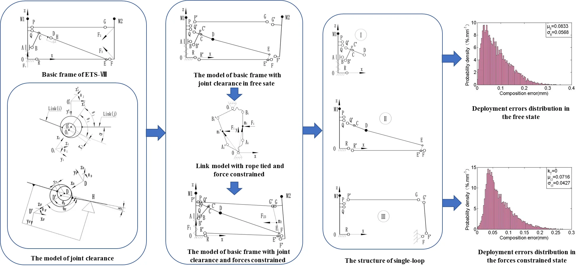
Highlights
- The effects on deployment accuracy of joint clearances and force are investigated.
- A virtual massless rope is used to describe the joint clearance for avoiding the singularities.
- The criterion of mechanism in stable configuration is obtained.
- The Monte-Carlo method and genetic algorithm are combined for solving and analyzing the deployment error.
1. Introduction
Deployable mechanism has been widely applied in the supporting device of space equipment such as flexible solar panels, satellite antenna or space telescope for the characteristics of big stowed volume ratio, light weight, high structural accuracy, etc. And the deployment accuracy is the key to ensure the normal operation [1-4]. Common deployable mechanisms are constructed with hinged bars as well as with the tightrope connected for enhancing stability [5-8]. In practice, the joint clearance is inevitable due to manufacture errors and the need for superior rotation capability. It performs a kinematic uncertainty on mechanism, and affects the deployment accuracy [9-14].
Plenty of researchers have been devoted to studying the influence of joint clearance. Most of the studies concentrated on single-loop linkage [15-20], but the common deployable mechanisms are multi-loop linkages that have loop constraints coupling and complicated topology structure [21, 22]. The analytical method used in single-loop linkage may not be applicable to it on account of challenges of highly nonlinear and strong coupling. Few achievements have been obtained on accuracy analysis of multi-loop linkage with joint clearances to be considered, Yang Y et al. [22] have analysed the relationships between distortion of whole mechanism and deviation of each rod based on the minimum of elastic deformation energy and Lagrange multiplier method, but the influence of joint clearance has not been considered. Ding J. and Wang C. [23] have decoupled the multi-loop mechanism with joint clearances based on matrix method and particle swarm optimization, but they only have investigated the maximum deployment error. Tsai M. J and Lai T. H. [24] provided a generalized method for error analysis of multi-loop mechanism with joint clearance on the base of screw theory, however, the effort to diminish the influence of joint clearance on the mechanism accuracy has not involved. Zhang X. and Zhang X. [25] have minimized the influence of joint clearance by controlling the redundant actuations of mechanism of which the redundant degree of freedoms and actuations are needed, and result in complex controlling and configuration change of mechanism.
Furthermore, the solution procedure of error involves an optimization problem of the nonlinear objective function with multiple constraints and strong coupling. So, it is difficult to be solved by traditional solutions. Heuristic algorithm is an important means to solve this problem, but it is still in the research phase. The classical algorithms have a lot of probability with the deficiencies of solving inefficiency, poor robustness and easy to fall into local optimal solution. It is usually necessary to improve the algorithm according to the actual tasks, or even a need of several algorithms collaboration to handle complex tasks. For instance, to improve the efficiency, Liu Q. et al. [26] proposed a speculative approach to spatial-temporal efficiency with multi-objective optimization by using Kernel-based Extreme Learning Machine algorithm and TS-NSGA-Ⅱ. Kong Y. et al. [27] proposed a belief propagation-based method. Deng W et al. [28] investigated an improved adaptive particle swarm optimization(DOADAPO) algorithm based on making full use of the advantages of Alpha-stable distribution and dynamic fractional calculus. Rong H. et al. [29] proposed a novel K+-isomorphism method and an improved MPD-V method. In addition, in order to accomplish the complex tasks, some current techniques are combined with the K+-isomorphism method. And in order to avoid the algorithm to get into the local optimal solution as well as to improve the robustness and the solution accuracy of the algorithm, Gu B. and Sheng V. S. [30] proposed a robust regularization path algorithm based on a new equivalent dual formulation for ν-SVC and a robust ν-SvcPath. Yu Xue et al. [31] introduced a self-adaptive mechanism of the artificial bee colony algorithm. Deng W. et al. [32] proposed a genetic and ant colony adaptive collaborative optimization (MGACACO) algorithm by introducing the chaotic optimization method, multi-population collaborative strategy and adaptive control parameters into the GA and ACO algorithm.
The object of this study is to propose an accuracy analysis method for multi-loop mechanism with joint clearance and to provide an approach for improving the deployment accuracy without any redundant actuation added. First, the equivalent model of deployable mechanism with joint clearance is obtained by converting the joint clearance into “a virtual massless link”. And in order to decouple the multi-loop, the geometrical relationship is expressed based on Denavit-Hartenberg (D-H) theory, while to split the multi-loop linkage into some single-loop linkages that subject to the same constraints. Besides, the deployment error is analysed by simulating the manufacture errors and the state of joint clearance without any constraint on deployable mechanism (the free state) with the use of Monte-Carlo method. In addition, the influence of the forces acting on the deployable mechanism is researched for diminishing the deployment error. “A virtual massless rope” is used instead of “a virtual massless link” for modelling the deployable mechanism with joint clearance and forces constrained. The criterion of mechanism in stable configuration is obtained by weighting coefficient method on the basis of minimum potential principle. And according to the characteristics of deployment error model, the Monte-Carlo method and genetic algorithm are combined to solve and analyse the deployment error with forces constraint. Furthermore, this research provides a reference for error correction and system reliability analysis of mechanism.
2. Configurations of cable-strut deployable mechanism
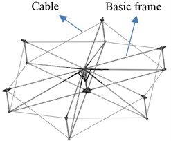
This study is based on the antenna supporting mechanism of the Engineering Test Satellite Ⅷ(ETS-Ⅷ) for the research [33]. The supporting mechanism consists of 14 basic modules, and every basic module contains 6 basic frames. In addition, the adjacent basic frames are connected by cables for improving the rigidity and stability, as shown in Fig. 1.
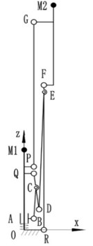
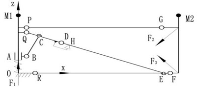
The basic frame is the bases of the antenna supporting mechanism to get the capabilities of deployment and keeping deployment accuracy. Fig. 2 shows the working principle. The slider A moves along the y direction under the action of spring, and drives the hinged bars to motion until the link DE reached the mechanical limit point H where the link DE and QD are collinear and cables are tight. So, the mechanism is self-locked and subjected to tension and spring load while in deployed state. M1 and M2 in Fig. 2 are the fixed positions of support cables [33] that the positional accuracy in deployed state operating a directly effect on surface accuracy of antenna.
Fig. 1Basic module of ETS-Ⅷ
a) Deployed state

b) Folded state
Fig. 2Basic frame of ETS-Ⅷ
a) Folded state
b) Deployed state
3. Model of cable-strut deployable mechanism with joint clearances
The basic frame of ETS-Ⅷ is a single degree of freedom mechanism that contains one sliding pair and 9 revolute joints. The clearance exists in any motion pair for motion needed and manufacturing error. In order to improve reliability, the linear bearing is used for precisely fitting together with axis in sliding pair, the clearance is minimal and can be neglected. So, the model of basic frame can be simplified into a mechanism only with joint pairs.
3.1. Equivalent model of joint clearance
The basic frame pose of ETS-Ⅷ will no longer change as it reached the limit position where every link is in the stable state of force balance, so the revolute joints are met to the contact hypothesis that the hole and shaft can be regarded as always stay in touch. And the basic frame can be treated as a multi-rigid-body system for the less stress and shock. Therefor the joint clearance can be modelled as “a virtual massless link” [34], as shown in Fig. 3, the eccentricity of the hole and shaft ri is described as “a virtual massless link” that both ends are respectively hinged with the centres of the hole and shaft.
Fig. 3The model of joint clearance
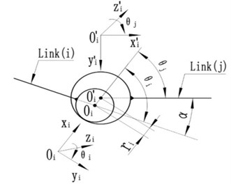
ri is a normal-distributed random variable which determined by the tolerance of hole and shaft. According to the 3 σ principles, almost all values of ri can be obtained in the interval (μ-3σ, μ+3σ), the mean value μi and standard deviation σi of ri are known by Eq. (1):
where max(ri) and min(ri) denote respectively the maximum and minimum of clearance.
Building the reference frames and orienting the positive direction of azimuth angles θi, θj of links based on D-H theory. Where θi is the azimuth angle of “virtual massless link” OiOi' relative to link i, θj is the azimuth angle of link j relative to “virtual massless link” OiOi', and meet the relationship of Eq. (2):
where α is the azimuth angle of link j relative to link i which are linked by revolute pair with joint clearance.
3.2. Deployment error model in the free state
While regardless the influence of forces such as cable-tension, spring force, etc., the relative position between the hole and shaft of the revolute pair is conform to random, i.e., while the “virtual massless link” in a free state, its azimuth angle θi obey the uniform random distribution in [-π, π), and the θi is a constant value at any certain moment. Fig. 4 shows the model of basic frame with joint clearance that based on the “virtual massless link”, and it only has one degree of freedom for the “virtual massless links” are stationary at any certain moment. For the joint clearance at D point, there is an angle β between link DE and link Q'D after basic frame into the deployed state, as shown in Fig. 5.
According to sine theorem, the relationship can be expressed as follow:
By Eq. (3):
According to the definition of D-H theory:
where θD and θD' are the azimuth angles of link DD' relative to link Q'D and link D'H relative to link DD', respectively; rD is the eccentricity of the hole and shaft at hinged point D, lDH is the distance of point D and H.
Fig. 4The model of basic frame with joint clearance in free sate
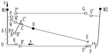
Fig. 5The model of revolute joint D with clearance
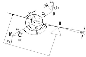
For easy to analysis, splitting the basic frame model (Fig. 4) into three single-loop models of Ⅰ, Ⅱ, Ⅲ, as shown in Fig. 6 which subject to the same constraints to model in Fig. 4.
Fig. 6The structure of single-loop
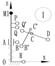
a) Loop Ⅰ
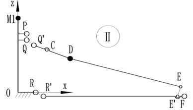
b) Loop Ⅱ
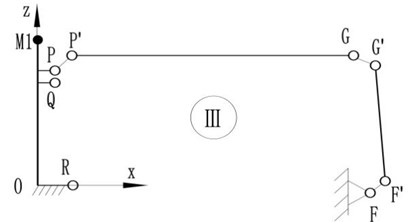
c) Loop Ⅲ
Let i,j∈{O,P,P',Q,Q',R,R',B,B',C,C',D,D',E,E',F,F',G,G',M2}, and Tji be the conversion matrix of reference frame oj-xjyjzj to oi-xiyizi. Attaching moving frame oi-xiyizi to the revolute joints of loop Ⅰ, Ⅱ, Ⅲ based on D-H theory, so the general conversion matrix between two reference frames can be given as follow:
where:
lj is the measured distance from oj to oi along xj, ωj is the rotation angle from zj to zi around xj, di is the measured distance from xj to xi along zi, θi is the rotation angle from xj to xi around zi.
Therefore, the relationships in the fixed reference frame o-xyz of points on basic frame can be expressed as follows:
Loop Ⅰ:
Loop Ⅱ:
Loop Ⅲ:
The basic frame is a multi-closed loop, and the clearance in slider A is ignored, so the following constraints should be met:
Besides, for the clearance of revolute joint, the azimuth angle of link j relative to link i has an additional angle αr relative to the theoretical angle α0, so Eq. (2) can also be written as follow:
where α0 is a constant value and αr is a uniform random variable in a small limited range that decide by the clearance of each joint.
So, the clearances caused deployment error in the free state can be obtained:
where [xi,yi,zi]T is the theoretical coordinate value in fixed reference frame o-xyz of point i.
3.3. Deployment error model with considering forces influence
As shown in Fig. 4, the “virtual massless link” can both bear the tension and stress. It provides an extra support for the basic frame which is non-existent in the actual stressing state of the joint with clearance and may fall into the extra singularities. Therefore, “a virtual massless rope” which is inelastic and can only bear tension is appropriate instead of “virtual massless link” to describe the clearance of joint. The basic frame is a multiple-degree-of-freedom system while in the forces constrained state, the azimuth angles of “virtual massless rope” and links can be expressed as follows:
where Fi, i= 1, 2,…, n denotes the force vector that acting on basic frame.
Take the infinite point along the Fi direction as the zero potential energy point, so the location of minimum potential energy can be achieved at the extreme position of the motion rang along the Fi direction:
where αi is a variable of θi that denotes the angle between mi and Fi, lOAi and lOiBi denote the lengths of the tethers at both ends of link AiBi, respectively.
Fig. 7Link model with rope tied and force constrained
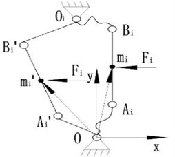
For the microgravity conditions and the slowly deploy speed of satellite antenna, the gravity and inertial forces can be ignored, so the basic module can be approximated as a system only bearing spring force and cable-tension. The cable-tension can be equivalent to the forces that point to the centre of the basic module, as shown in Fig. 8.
Fig. 8The model of basic frame with joint clearance and forces constrained
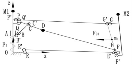
The spring force F1 acts on slider A along the positive direction of z axis. The resultant force of cable-tension F23 directly acts on link FG along the negative direction of x axis. So, the basic fame with these forces constrained should not only meet the geometrical relationships as described in the free state, but also need to meet the following equilibrium criterion:
where m1 and m2 are the position vectors in fixed reference frame o-xyz of the middle points of revolute joint B and link F'G', respectively. The weights kT and kz are for the spring force and cable-tension, where kT+kz= 1. By choosing kT= 1 an equilibrium criterion of the system only with spring force constrained is found, while setting kz= 1 enables one to obtain an equilibrium criterion of the system only with cable-tension constrained. The values of the weights kT and kz can be chosen in order to obtain the equilibrium criterion of the system with various spring forces and cable-tensions constrained.
The deployment error with considering forces influence δc can be obtained from Eq. (19) by subjecting to the equilibrium criterion as described in Eq. (22).
4. Deployment error solutions
4.1. geometric parameters
According to the selected fit tolerances, all joint clearances ri are within the range of 0.01-0.04 mm. Table 1 gives the theory coordinates of joints in the fixed reference frame o-xyz.
Table 1Theory coordinates of joints
Joint | Theory coordinate (mm) |
P | (30.00, 0, 500.00) |
Q | (30.00, 0, 480.00) |
R | (85.00, 0, 0) |
B | (30.00, 0, 231.59) |
C | (130.91, 0, 454.85) |
D | (309.67, 0, 410.29) |
E | (1496.36, 0, 114.49) |
F | (1516.30, 0, 116.11) |
G | (1418.53, 0, 563.89) |
H | (324.23, 0, 406.66) |
M2 | (1489.00, 0, 721.24) |
4.2. Solution of the deployment error in free state
Using the Monte-Carlo method to simulate the values of joint clearances and azimuth angles, i.e. it provides various kinds (the number is 104 in this study) of the deployment configurations of basic frame. Then calculate the deployment errors δf of the obtained configurations. Fig. 9 shows the results. The mean errors in the x axis and z axis direction are μfx= –0.0056 mm and μfz= 0.0242 mm, respectively. And the standard deviations are σfx= 0.0344 mm and σfz= 0.0915 mm, the maximum errors are δfx= 0.1111 mm and δfz= 0.3393 mm. The mean, standard deviation and maximum value of composition errors (the distance between actual location and theoretical location) of the fixed position of support cables M2 are μfl= 0.0833 mm, σfl= 0.0568 mm and δfl= 0.3537 mm, respectively. This shows that, the joint clearances have a great effect on the deployment error in the z axis direction.
Fig. 9Deployment errors distribution in the free state
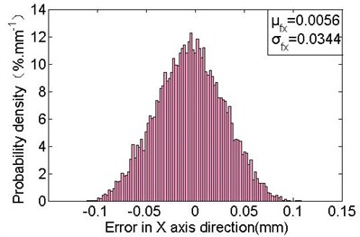
a) Deployment errors distribution in the x axis direction
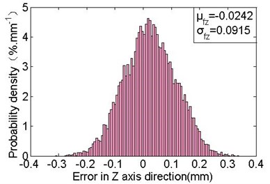
b) Deployment errors distribution in the z axis direction
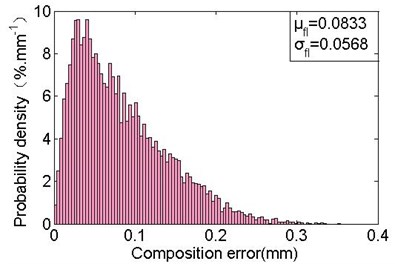
c) Composition deployment errors distribution
4.3. Solution of the deployment error with considering forces influence
The deployment configuration of basic frame with forces constrained should subject the constraint as defined in Eq. 22. Therefore, the solution procedure of error δc involves an optimization problem of the nonlinear objective function with multiple constraints and strong coupling. So, the Monte-Carlo method and genetic algorithm are combined (as shown in Fig. 10) for solving the deployment error δc.
Constructing the fitness function by objective function f(fθi), as shown in Eq. (23) and Eq. (24):
where c is the conservative value of the maximum value of f(fθi) that can be obtained from formula c=kTzQ-kzxG, k is the control parameter of fitness, and f'max, f'min, f'avg denote respectively the maximum, minimum and average values of fitness, which are solutions from Eq. (23) within contemporary populations. When f'max-f'avg<f'avg-f'min, indicating that the fewer optimal individuals, so should make the optimal one has the distance of maximum to k+ 1 times from the worst one by Eq. (24). And as a result, to enhance the ability of superior individuals.
In the solution procedure, set the population size to 50, the maximum number of generation to 100, and the simulation number of Monte-Carlo method to 104. The mean μc and the standard deviation σc of the obtained deployment errors obey the variation laws versus kT, as shown in Fig. 11. The standard deviations σcx and σcz respectively of the deployment errors in the x axis and z axis direction are monotone increasing with the increasing of kT. The standard deviation σcl of composition errors is monotone increasing while kT≤ 0.5, and it tend to be stable with a slightly reduction as kT> 0.5. While kT= 1,σcx= 0.0302 mm, σcz= 0.0788 mm, σcl= 0.0489 mm, which are slightly less than the standard deviations of the errors in free state. It suggests that the spring force operating a micro effect on reducing the range of deployment errors, i.e. it has a slightly effect on repeat deployment accuracy.
Fig. 10Solution procedure of deployment error with considering forces influence
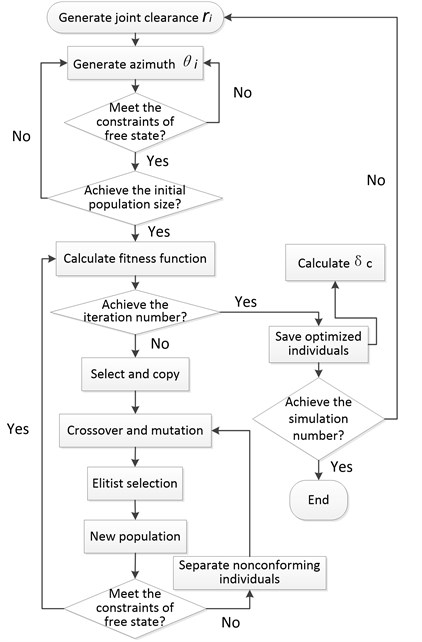
Fig. 11The variation laws of error characteristics
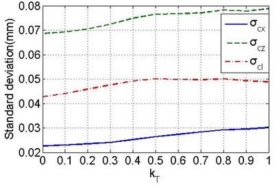
a) The variation laws of standard deviations
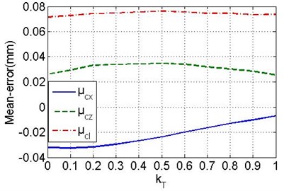
b) The variation laws of mean errors
Also, it can be found that the deployment error fluctuates in a smaller scope with the increasing of cable-tension, especially when kT< 0.2, the standard deviation is gradually stabilising. So, it is effectively in improving the repeat accuracy by increasing cable-tension. Actually, the designed cable-tension |F23| and spring force |F1| optimal to have the difference of at least four times, and the spring force should not be enhanced while other requirements of basic frame are satisfied for decreasing the required cable-tension. The minimum standard deviations with the values of σcx= 0.0227 mm, σcz= 0.0687 mm and σcl= 0.0427 mm are obtained while kT= 0, which are decreased respectively by 34 %, 25 % and 25 % as comparing with the values in free state. The corresponding mean errors are μcx= –0.0321 mm (5.7 times than the free state), μcz= 0.0261 mm, μcl= 0.0716 mm, respectively. Fig. 12 shows the probability density distribution, obviously, the errors are more centralized, and the mean error in the x axis direction is much larger compared with the free state (as shown in Fig. 9). It indicates that the cable-tension offsets the links along the force direction. In addition, the actual deployment accuracy can be improved by optimizing the deployment position of point M2 to the new M2 (1489.0321, 0, 721.2139), which has the offsets of -μcx and -μcz.
Fig. 12Deployment errors distribution with only considering cable-tension influence
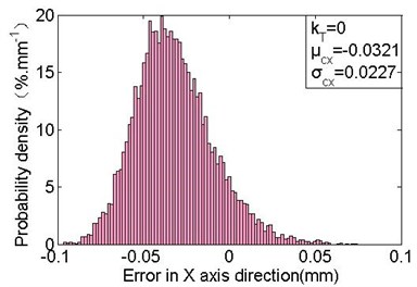
a) Deployment errors distribution in the x axis direction
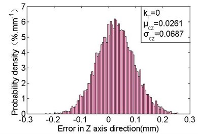
b) Deployment errors distribution in the z axis direction
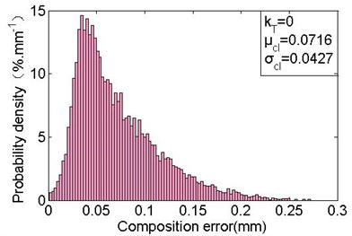
c) Composition deployment errors distribution
5. Conclusions
In this study, the “virtual massless links” are used to replace the joint clearances of deployable mechanism which is in the free state. Based on the same constraints, the deployable mechanism with multi-loop structure is decomposed into some single-loop structures, and the relationship of them is obtained by D-H theory. Furthermore, the deployment error distribution regularities are revealed benefit from the applying of Monte-Carlo method. Besides, the forces effect on deployment error is investigated. First, the equivalent model that without any extra singular configuration of the deployable mechanism with joint clearances and forces constrained is obtained by using “virtual massless rope” instead of “virtual massless link”. Then, the stable configuration criterion of mechanism with forces constrained is presented. Finally, the deployment error with forces influence is solved by combining the Monte-Carlo method and genetic algorithm. And a comparative analysis between this result and the deployment error in free state is provided. It indicates that the acting forces are effective in improving the repetitive deployment accuracy of mechanism with joint clearance. In addition, an error correction approach is introduced for further improving the deployment accuracy.
References
-
Tibert G. Deployable Tensegrity Structures for Space Applications. Royal Institute of Technology Department of Mechanics, 2002.
-
Datashvili L. Foldability of hinged-rod systems applicable to deployable space structures. CEAS Space Journal, Vol. 5, Issue 3, 2013, p. 157-168.
-
Wang Y., Liu R., Yang H., et al. Design and deployment analysis of modular deployable structure for large antennas. Journal of Spacecraft and Rockets, Vol. 52, Issue 4, 2015, p. 1-11.
-
Guo H. W., Deng Z. Q., Liu R. Q. Parameter design and precision measurement of space cable-strut deployable articulated mast. Optics and Precision Engineering, Vol. 18, Issue 5, 2010, p. 1105-1111.
-
You Z., Pellegrino S. Cable-stiffened pantographic deployable structures. Part 1: Triangular mast. AIAA Journal, Vol. 34, Issue 4, 1996, p. 813-820.
-
You Z., Pellegrino S., You Z., et al. Cable-stiffened pantographic deployable structures part 2: mesh reflector. AIAA Journal, Vol. 35, Issue 8, 1997, p. 813-820.
-
You G., Yang P. Multiobjective shape optimization for deployment and adjustment properties of cable-net of deployable antenna. Mathematical Problems in Engineering, 2015, https://doi.org/10.1155/2015/384659.
-
Zhang J., Guo H. W., Liu R. Q., et al. Nonlinear dynamic characteristic analysis of jointed beam with clearance. Acta Astronautica, Vol. 129, 2016, p. 135-146.
-
Tsai M. J., Lai T. H. Kinematic sensitivity analysis of linkage with joint clearance based on transmission quality. Mechanism and Machine Theory, Vol. 39, Issue 39, 2004, p. 1189-1206.
-
Sun D., Chen G. Kinematic accuracy analysis of planar mechanisms with clearance involving random and epistemic uncertainty. European Journal of Mechanics – A/Solids, Vol. 58, 2016, p. 256-261.
-
Li J., Huang H., Yan S., et al. Kinematic accuracy and dynamic performance of a simple planar space deployable mechanism with joint clearance considering parameter uncertainty. Acta Astronautica, Vol. 136, 2017, p. 34-45.
-
Geng X., Wang X., Wang L., et al. Non-probabilistic time-dependent kinematic reliability assessment for function generation mechanisms with joint clearances. Mechanism and Machine Theory, Vol. 104, 2016, p. 202-221.
-
Erkaya S., İbrahim Uzmay Optimization of transmission angle for slider-crank mechanism with joint clearances. Structural and Multidisciplinary Optimization, Vol. 37, Issue 5, 2008, p. 493-508.
-
Erkaya S., İbrahim Uzmay Investigation on effect of joint clearance on dynamics of four-bar mechanism. Nonlinear Dynamics, Vol. 58, Issue 1, 2009, p. 179-198.
-
Bauchau O. A., Rodriguez J. Modeling of joints with clearance in flexible multibody systems. International Journal of Solids and Structures, Vol. 39, Issue 1, 2002, p. 41-63.
-
Erkaya S., İbrahim Uzmay Determining link parameters using genetic algorithm in mechanisms with joint clearance. Mechanism and Machine Theory, Vol. 44, Issue 1, 2009, p. 222-234.
-
Jawale H. P., Thorat H. T. Investigation of positional error in two degree of freedom mechanism with joint clearance. Journal of Mechanisms and Robotics, Vol. 4, Issue 1, 2012, p. 11002-1.
-
Daniali H. M., Varedi S. M., Dardel M., et al. A novel algorithm for kinematic and dynamic optimal synthesis of planar four-bar mechanisms with joint clearance. Journal of Mechanical Science and Technology, Vol. 29, Issue 5, 2015, p. 2059-2065.
-
Yan S., Guo P. Kinematic accuracy analysis of flexible mechanisms with uncertain link lengths and joint clearances. Proceedings of the Institution of Mechanical Engineers Part C Journal of Mechanical Engineering Science, Vol. 225, Issue 8, 2011, p. 1973-1983.
-
Erkaya S., İbrahim Uzmay Modeling and simulation of joint clearance effects on mechanisms having rigid and flexible links. Journal of Mechanical Science and Technology, Vol. 28, Issue 8, 2014, p. 2979-2986.
-
Yang Y., Xie S., Zhang W., et al. Accuracy model, analysis, and adjustment in the context of multi-closed-loop planar deployable mechanisms. Advances in Mechanical Engineering, Vol. 8, Issue 3, 2016, p. 1-15.
-
Yang Y., Luo J., Zhang W., et al. Accuracy analysis of a multi-closed-loop deployable mechanism. Proceedings of the Institution of Mechanical Engineers Part C Journal of Mechanical Engineering Science, Vol. 230, Issue 4, 2014, p. 611-621.
-
Ding J., Wang C. Deployment accuracy analysis of planar satellite antenna with joint clearances. Journal of Beijing University of Aeronautics and Astronautics, Vol. 42, Issue 12, 2016, p. 2625-2631.
-
Tsai M. J., Lai T. H. Accuracy analysis of a multi-loop linkage with joint clearances. Mechanism and Machine Theory, Vol. 43, Issue 9, 2008, p. 1141-1157.
-
Zhang X., Zhang X. Minimizing the influence of revolute joint clearance using the planar redundantly actuated mechanism. Robotics and Computer-Integrated Manufacturing, Vol. 46, 2017, p. 104-113.
-
Liu Q., Cai W., Shen J., et al. A speculative approach to spatial‐temporal efficiency with multi-objective optimization in a heterogeneous cloud environment. Security and Communication Networks, Vol. 9, Issue 17, 2016, p. 4002-4012.
-
Kong Y., Zhang M., Ye D. A belief propagation-based method for task allocation in open and dynamic cloud environments. Knowledge-Based Systems, Vol. 115, 2016, p. 123-132.
-
Deng W., Zhao H., Yang X., et al. Study on an improved adaptive PSO algorithm for solving multi-objective gate assignment. Applied Soft Computing, Vol. 59, 2017, p. 288-302.
-
Rong H., Ma T., Tang M., et al. A novel subgraph K+-isomorphism method in social network based on graph similarity detection. Soft Computing, 2017, https://doi.org/10.1007/s00500-017-2513-y.
-
Gu B., Sheng V. S. A robust regularization path algorithm for ν-support vector classification. IEEE Transactions on Neural Networks and Learning Systems, Vol. 28, 2017, p. 5-1241.
-
Yu Xue, Jiongming Jiang, Binping Zhao, et al. A self-adaptive artificial bee colony algorithm based on global best for global optimization. Soft Computing, Vol. 8, 2017, p. 1-18.
-
Deng W., Zhao H., Zou L., et al. A novel collaborative optimization algorithm in solving complex optimization problems. Soft Computing, Vol. 21, Issue 15, 2017, p. 4387-4398.
-
Meguro A., Ishikawa H., Tsujihata A. Study on Ground Verification for Large Deployable Modular Structures. Journal of Spacecraft and Rockets, Vol. 43, Issue 4, 2006, p. 780-787.
-
Guo H., Yuo W. Design optimization of planar linkage mechanism with joint clearance for improving the robustness of kinematic accuracy. Journal of Mechanical Engineering, Vol. 48, Issue 3, 2012, p. 75-81.
Cited by
About this article
The study of the paper is supported by National Natural Science Foundation of P. R. China (No. 51675264) and Basic Scientific Research Business Expenses of Nanjing University of Aeronautics and Astronautics (No. NE2017105).
Lin Fei presents the method described in this paper, and is responsible for writing. Chen Meng provides guidance for this paper. Chen Chuanzhi is responsible for programming. Chen Jinbao provides the research background of this paper. Dong Zirui is responsible for literature review. Zhou Jinhua is responsible for data processing.
