Abstract
Wave-average area morphologic change numerical modelling system, CST3D, is adopted to reproduce tombolo and salient evolution behind a detached breakwater at a laboratory. The numerical wave-average morphologic model equips the beachface slope controlling method. Beachface slope varies between two extreme values for erosion and siltation modes. The beachface slope is checked every time step, and the morphology at the beachface and flat surf terrace is modified, if necessary. The model system reproduced tombolo and salient evolution for 2 cases of Ming and Chiew’s experiments. Model results implies the length of the detached emerged structure plays an important role on formation of tombolos.
1. Introduction
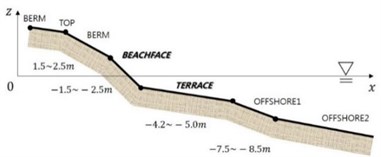
Tombolo or salient plays an important role to control coastal morpology. Shoreline change is of great interest to many coastal engineers. Korean East Sea has micro-tidal beach, and high waves. Beach profiles have been measured several times in 2013 and 2014 at Anmok and Namhangjin Beaches on the east coast of Korea [1]. Measured profiles show more or less similar style, see Fig. 1. Mean tidal range at the site is around 10-20 cm. The offshore-bar-average flat terrace also shows stable slope and depth. The beachface slope and the beachface foot level at the site seem very stable. The shape of the berm top and the berm body varies site by site depending on the land use status. The fact that beachface retains straightness between the top and the foot in shape, and that the beachface slope remains relatively constant throughout a year is promising from the engineering point of view. The offshore bar-average flat terrace also shows stable slope and depth. The measured beachface slope at Anmok and Namhanjin beaches are within 7° to 10° in 2013 and 2014, and its average value is 8.5°. It is thought that the slope is steep during eroding phase, and mild during siltating phase.
Fig. 1Typical beach profile style at Anmok and Namhangjin Beaches
Many emerged or submerged detached breakwaters have been constructed to induce salients or tombolos, and are still under assessment on their success. It is important to reproduce or predict tombolo evolution behind breakwater by using a tool including numerical modelling. Ranasinghe et al. [2] proposed an empirical formula to distinguish erosiveness of shoreline behind submerged detached breakwaters, which was based on their numerical modelling results. However, their distingction criteria on erosion or deposition was not clearly explained. Johnson et al. [3] also proposed an engineering tool for design of detached breakwater, but its use is limited for macro-tidal coasts.
CFD type models or Boussinesq type models could simulate sediment transport around beachface, morphologic change up to runup height and consequent shoreline evolution, but require heavy computation. A simple end of simulation methods for shoreline evolution is the line models [4]. Line models are useful to predict long-term shoreline evolution around simple structures, but fail to simulate tombolo formation or spit growth which involves wild shoreline deformation because of their parallel or almost parallel grid system adopted.
General wave-average area models may have merits to simulate shoreline evolution for arbitrary geometry. However, the difficulty in treatment of shoreward boundary has hindered the use of this type of approach for simulation of shoreline evolution. The major defect is that it is impossible to simulate morphologic change above the wave-average water level, although it is more or less hidden for macro-tidal environment.
There have been a few trials to model shoreline retreat within wave-average area modelling approach. These include the diffusion method [5], the wet-dry cell method [6], and the cut-cell method [6]; these lack capabilities of simulation of shoreline advance. Another group of trials modelled shoreline advance as well: the fixed profile method [7], the coupling area-line method [8-10] and area-crossshore-alongshore transport coupling method [11-13]. The fixed profile method has not yet been expanded for general morphology. The coupling method runs an area model, and transfers output to a line or N-line models. However, it involves wild assumptions, and its application is limited to fairly simple morphology. Kuroiwa et al. [14, 15] included crossshore sediment transport and alongshore sediment transport in their area model. However, the cross-shore and alongshore directions are preliminarily defined at the beginning of simulation, and therefore the tombolo evolution with wild shoreline deformation cannot be properly simulated. The assumption of linear distribution of cross-shore transport rate adopted in their model may cause unrealishic parabolic beachface profile, and may require future adjustment. Kuchiishi et al. [12] and Fujiwara et al. [13] showed shoreline evolution around river mouths and detached breakwater by using both wave-induced and current-induced sediment transport, However, the nearshore wave-induced sediment transport rate requires future verification. A new method with management of the beachface slope to simulate the shoreline evolution of arbitrary shape within an area morphological model is proposed here.
2. Beachface slope controlling method
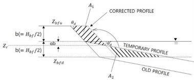
We assume that the beachface part of a beach profile is uniform-sloped, and the upper part of the terrace below the beachface foot is also nearly uniform-sloped. The shoreline may proceed in depositing phase or retreat in eroding phase during a certain period. If interirim model results reveal siltation on the lower half of the beachface and terrace so that the beachface slope becomes milder than the minimum one, then the temporary profile is artificially adjusted to restore the minimum beachface slope by moving some sediment budget on to dry zone, see Fig. 2. In the figure b is half of the beachface height, is the lower limit slope, is the temporary slope milder than the limit slope, and is the portion of the height of neutral position where both volumes become identical relative to the beachface height. should be the same as . We get 0.25. The parameter becomes 0.25 if the profile lines are straight.
Fig. 2Beachface slope control with regard to reference height during depositing phase
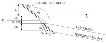
On the other hand, if interim model results reveal erosion on the lower half of the beachface and terrace, so that the beachface slope becomes steeper than the maximum slope, then the temporary profile is artificially adjusted to restore the maximum beachface slope by dumping some sediment volume to underwater zone, see Fig. 3. In this case the parameter is related to another parameter , whichis a proportion of the ambient depth under erosion relative to the beachface height. and should be identical for sediment mass conservation. becomes 0.25 for 0, when the average erosion depth at surrounding bed is zero.
Fig. 3Beachface slope control with regard to reference height during eroding phase
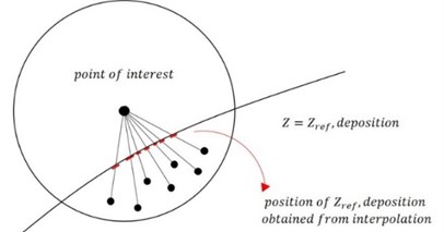
Shorelines are not always straight, especially around headlands or structures. Shoreline angle varies smoothly in space, and shoreline angle may deviate from straight line sharply around tombolos or salient, see Fig. 4. We want to apply the above adjustment along cross-sections, and we need to find the orthogonal profile for every given grid cell on the beachface. A nearly orthogonal profile can be found by choosing the shortest distance among many distances between the point of interest and the contour line of the reference level, , by interpolation of the depths of the point of interest and a cell point within a checking radius, see Fig. 5.
Fig. 4Three-dimensional morphological modification for deposition phase: shoreline advances
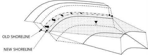
Fig. 5Finding control cross-section for the point of interest from many cell depths below reference level
3. Simulation results
Ming and Chiew [16] carried out laboratory experiments on salient or tombolo formation starting from plane-sloped beach, and presented their experimental results; results was divided into tombolos, salients, and no form. The above algorithm is adopted in a numerical modelling system CST3D-v2016 [17], and applied to two cases of Ming and Chiew’s laboratory experiments of Table 1. The numerical modeling system is semi-three-dimensional; sigma coordinated; and containing wave, flow, sediment transport, and morphological change sub-modules. Horizontal mixing of bed sediment due to wave action proportional to the number of grid points across the surf zone [18] is also included in the model as a smoothing process of morphology.
Table 1Ming and Chiew’s [14] test conditions and experimental results
Case | (m) | (m) | (cm) | (m) | (cm) | (s) | (m) | (h) | (m) | (m) | |
1-7 | 1.50 | 0.90 | 8.00 | 0.50 | 5.00 | 0.85 | 0.335 | 0.044 | 19.0 | 0.900 | 0.557 |
1-4 | 0.60 | 0.90 | 8.00 | 0.50 | 5.00 | 0.85 | 0.335 | 0.044 | 18.0 | 0.240 | 0.138 |
The symbols in Table 1 are defined as: is deep water wave height; is deep water wave steepness; is water depth at the breakwater; is wave period; is deep water wavelength; is water depth in the wave basin; is test duration; is length of the breakwater; is distance of the breakwater to the initial shoreline; is distance of the initial breaker line to the initial shoreline; is distance of the salient apex to the initial shoreline; and is plan area of sand deposition, namely the area enclosed by the initial shoreline and the shoreward equilibrium shoreline. Note that the shoreline refers to the still water line.
Model results include wave field, flow-driving force field, wave-induced current field, wave- average bed shear stress field under the flow and wave conditions, sediment eroding/depositing rate field, modified morphology by wave and current, and the accompanying modified shoreline.
Fig. 6Computed wave field with SWAN for Case 1-7 and 1-4: arrow size is wave height; arrow direction is wave direction
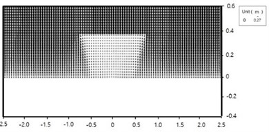
a) Case 1-7
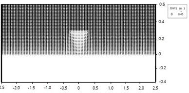
b) Case 1-4
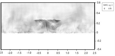
Fig. 7Computed wave-induce current field for Case 1-7 and 1-4: arrow size is current speed; arrow direction is current direction
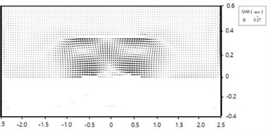
a) Case 1-7
b) Case 1-4
The computed wave fields using SWAN for the two cases are shown in Figs. 6. Wave height behind the breakwaters are small due to diffraction. The computed wave-induced current fields for the two cases are shown in Figs. 7. Wave-induced driving forces are strong around shoreline at the lee of the breakwater due to uneven wave breaker line. Wave-induced currents are strong behind the breakwater; forming two strong wakes, the centreline of which is heading toward the breakwater. Both cases show a pair of circulation cells, but the sizes of the circulation cells are different. The size of the circulation cells of Case 1-7 is larger, and the current speed of the case is weaker. Two circulation cells in the lee side of the breakwater are closer to each other for Case 1-4, and the fluid particle velocity and the resultant bed shear stress along the centerline between the two cells are larger, which hinders tombolo growth. The two wakes play an important role in sediment transport and morphological change around the structures.
The smoothing step in Fig. 6(a) was added to the first intermediate morphology based on empirical experience. Smoothing of bed morphology represents lateral mixing of sediment due to wave action similar to horizontal mixing of fluid momentum.
Computed shoreline positions for the 2 cases are shown in Figs. 8-9, which are satisfactorily compared with laboratory measurements in Figs. 10-11. Both the computed time evolution of the distance of the salient apex to the initial shoreline, (a) and the computed time evolution of the attachment width of the tombolo at the detached breakwater (b) show asymptotic behavior towards equilibrium status, see Figs. 12(a) and (b).
Fig. 8Model result: Case 1-7
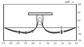
Fig. 9Ming and Chiew’s result: Case 1-7
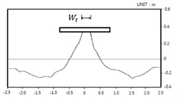
Fig. 10Model result: Case 1-4
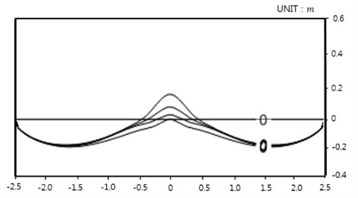
Fig. 11Ming and Chiew’s result: Case 1-4
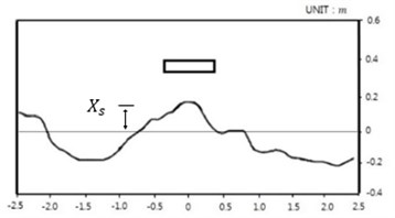
Fig. 12Computed time evolution of two lengths Xs and Wt
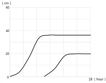
a) Case 1-7
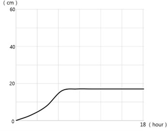
b) Case 1-4
4. Conclusions
Computed shoreline evolution for the two cases of Ming and Chiew’s experiments reproduced measurements satisfactorily. Both tombolo and salient cases were successfully simulated by the model system CST3D adopting the present beachface slope controlling method, and it is believed that model results improve our understanding of the difference between tombolo and salient. The model system could further be parameterized for engineering purposes. The present beachface slope adjustment method work well for cases of very wide angle deformation of shoreline, which cannot be simulated by existing one or N line models.
Regarding the length of a detached breakwater long breakwater helps tombolo formation. Modeling result clearly demonstrates that the design of an emerged breakwater should be supported by numerical modelling to make sure that whether intended salient or tombolo would evolve for given structure length, depth, and distance to the initial shoreline to obtain proper tombolo or salient.
References
-
Annual Report Coastal Erosion Monitoring (2nd year; 2013-2014). Gangwon Hwandonghae Headquarters, 2015.
-
Ranasinghe R., Larson M., Savioli J. Shoreline response to a single shore-parallel submerged breakwater. Coastal Engineering, Vol. 57, 2010, p. 1006-1017.
-
Johnson H., Wilkens J., Parsons A., Chesher T. Guidance for Outline Design of Nearshore Detached Breakwaters on Sandymacro-Tidal Coasts. Environment Agency Report: SCHO0210BRYO-E-P, Environment Agency, 2010.
-
Suh K., Hardaway C. Calculation of tombolo in shoreline numerical model. Coastal Engineering, 1995, p. 2653-2667.
-
Watanabe A., Maruyama K., Shimizu T., Sakakiyama T. A numerical prediction model of three-dimensional beach deformation around a structure. Coastal Engineering in Japan, 29, p. 1986-179.
-
Roelvink J. A., Lesser G., Van der Wegen M. Morphological modelling of the wet-dry interface at various timescales. Proceedings ICHE Conference, Philadelphia, 2006.
-
Jorissen J. G. L. Strandhoofden gemodelleerd in Delft3d-RAM. Delft University of Technology, 2001.
-
Shimizu T., Kumagai T., Watanabe A. Improved 3-D Beach evolution model coupled with the shoreline model (3D Shore). Coastal Engineering in Japan, Vol. 220, 1996, p. 2843-2856.
-
Van Koningsveld M., Van Kessel T., Walstra D. J. R. A hydrid modelling approach to coastal morphology. Coastal Dynamics Conference, Barcelona, Spain, 2005.
-
Nam P. T. Numerical Model of Beach Topograghy Evolution Due to Waves and Currents (Report 1051). Lund University, 2010.
-
Kuroiwa M., Kamphuis J. W., Kuchiishi T., Matsubara Y., Noda H. Medium-term Q-3D coastal area model with shoreline change around coastal structures. Proceedings of 29th International Conference on Coastal Engineering, 2004, p. 2194-2206.
-
Kuchiishi T., Kato K., Kuroiwa M., Matsubara Y. Applicability of 3D morphodynamic model with shoreline change using a Quasi-3D nearshore current model. International Offshore and Polar Engineering Conference, 2004, p. 715-723.
-
Fujiwara H., Uda T., Onishi T., Miyahara S., Serizawa M. Prediction of beach changes around artificial reef using BG model. Coastal Engineering Proceedings, Vol. 33, 2012.
-
Kuroiwa M., Kuchiishi T., Matsubara Y. Prediction system of 3D beach evolution with 2DH and Q3D hydrodynamic modes. Proceedings of 16th International Offshore and Polar Engineering Conference, 2006, p. 751-757.
-
Kuroiwa M., Kuchiishi T., Kato K., Sunagawa S., Matsubara Y. Applicability of coastal area model to morphodynamic around river mouth. Proceedings of 31st International Conference on Coastal Engineering, 2008, p. 2218-2230.
-
Ming D., Chiew Y.-M. Shoreline changes behind detached breakwater. Journal of Waterway, Port, Coastal, and Ocean Engineering, Vol. 126, 2000, p. 63-70.
-
Kim H. User Manual of CST3D-2013-v1. Haksan Media, 2013.
-
Kim H. Three-Dimensional Sediment Transport Model. Ph.D. Thesis, The University of Liverpool, Merseyside, UK, 1994.
Cited by
About this article
This work is a result of the research project, “Development of Coastal Erosion Control Technology”, funded by the Ministry of Oceans and Fisheries, Korea since 2013.
