Abstract
In this paper, the calculation model of the propulsion shafting structure was established to solve the problem of flexural vibration of the shafting system for the underwater vehicle with relatively small scale. By using the transfer matrix method and the finite element method, the vibration characteristics of the shafting system subjected to the transverse unsteady excitation force were calculated by MATLAB software and ABAQUS software. Two aspects of the displacement response and the vibration power flow were analyzed and compared. Analysis showed that the results of the two methods were very close to each other and all met the requirements of vibration engineering calculation. The influence of the mass of propeller and the bearing stiffness in different positions on the vibration characteristics were analyzed by using the transfer matrix method. Finally, based on the transfer matrix method, the parameters of the bearing stiffness at different supports were optimized with design optimization, and then use ABAQUS software to verify the effectiveness of the optimization. The analysis results showed that, after optimization calculation, the vibration power flow input to the bases of different bearings were significantly decreased.
1. Introduction
Underwater vehicle is one of the most important naval weapons in the world. With the improvement of underwater acoustic detection technology and the increasingly fierce underwater confrontation, the quiet underwater vehicle has become the goal pursued by all countries. When the underwater vehicle is sailing at high speed, the propeller is subjected to unsteady excitation force due to the non-uniformity of the flow field, which causes the vibration of the propulsion shafting. The vibration of the shafting can be transmitted to the shell through its supporting structure, which directly affects the vibration and noise performance of the vehicle. Therefore, the study on the vibration characteristics of the propulsion shafting and the optimization design of the supporting parameters are of guiding significance to the research of the low noise propulsion shafting and the noise control of the underwater vehicle.
Previously, a large number of researches on shafting vibration analysis and control mainly for ships, submarines, etc. have been carried out. Xie Jirong established a model for analyzing the vibration characteristics of propeller unsteady force to ship hull, analyzed the force transmission characteristics of shafting system and the influence of shafting design parameters on the vibration characteristics based on the calculation model of the shafting. Contrast analysis of real ship vibration test and finite element calculation results were relatively close [1]. Li Quanchao and Yu Qiang studied the effects of supporting parameters on marine shaft vibration characteristics and put forward the shafting vibration control design principles [2]. Wu Xianjun and Zhu Shijian brought out a calculation method of vibration power flow based on finite element analysis. Based on that, an optimization was performed at a single beam isolation system and the best vibration isolator parameters and fixing position were found, which made the vibration isolation efficiency greatly improved [3]. Li Haifeng and Lou Jingjun optimized the parameters of a large propulsion shafting by selecting the bearing stiffness and bearing spacing as the optimization parameters and selecting the sum of the power flow of each bearing of the shafting system as the optimization objective based on the modified Timoshenko beam theory using the transfer matrix method [4]. However, for the torpedo, underwater unmanned vehicle and other relatively small scale underwater vehicles, the vibration problem of the shafting system still exists but the current study is not sufficient.
In this paper, the basic propulsion shaft structure of an relatively small scale underwater vehicle was selected, and the shafting system was simplified as beam elements, elastic supporting elements and point mass elements. Firstly, based on the modified Timoshenko beam theory, the field transfer matrix and the point transfer matrix were established. Then, the corresponding boundary conditions were introduced and the transfer matrix method was used to calculate the dynamic response and the vibration power flow of each bearing support with MATLAB software. Furthermore, the corresponding finite element model was established with ABAQUS software, and the correctness of the theoretical solution of the transfer matrix method is verified by comparison. After that, took advantage of the convenience of the transfer matrix method, the influence of the propeller mass and the bearing stiffness on the vibration characteristics were analyzed. Finally, the parameters of the bearing stiffness at different supports were optimized with design optimization based on the transfer matrix method and the effect of optimization was verified by ABAQUS software.
2. Using transfer matrix method to calculate the vibration response of shafting
2.1. Calculation model and theory
According to the actual structure of the propulsion system of a certain type of underwater vehicle, a simplified model of the propulsion shafting is established, as shown in figure 1. The front end of the shaft is connected with the power output shaft through an flexible coupling, here the propulsion shafting system only retains the spline shaft and the tail shaft section. The supporting function of the power output shaft to the front end of the spline shaft is equivalent to the spring connection, and the working position is the spline sleeve of the node 7. The spline sleeve applies equivalent mass and the front end of the shaft is simply supported. This short shaft in the radial generally have two bearing support, tail bearings and front bearings, bearing support with equivalent spring treatment, respectively, node 2 and node 4. The propeller is treated with a mass element at node 1. The end of the shaft is free. In the whole shaft section, where there is a bearing, the equivalent lumped mass and material, shaft diameter changes are divided into separate sections of the shafting system.
Fig. 1Simplified model of propulsion shafting of underwater vehicle

Let the state vector of the cross section of the transfer matrix be Z=[yαMQ]. According to the modified Timoshenko beam theory, the flexural vibration equation is:
In the formula, k' is the effective shear coefficient of profile, EI is the Bending stiffness, E is the Young’s modulus, I is the Moment of inertia of beam cross section, G is the Shear modulus, m is the mass per unit length, the cross-sectional area is A. The field transfer matrix of section I beam element can be obtained by Eq. (1):
s1,2={[β4+14(δ+σ)2]12∓12(δ+σ)}12,
C1=s21+s22,C2=s21coss2+s22chs1,C3=coss2-chs1,
C4=(δ+s21)(δ-s22),C5=s1shs1+s2sins2,C6=s1sins2-s2shs1,
C7=s21chs1+s22coss2,C8=s31shs1-s32sins2,C9=s31sins2+s32shs1.
Thereinto, σ=mλ2L2i/EA, δ=mλ2L2i/k'AG, β4=mλ2L4i/EI.
There is a centralized mass point at node 1, and the point transfer matrix is:
Node 2 and node 4 have spring support, the point transfer matrix are as follows:
Node 7 has both concentrated mass and spring support, the point transfer matrix is:
The left end is the free end: the shear force and the bending moment are equal to zero:
The right end is simply supported: the displacement and bending moment are equal to zero:
Transverse unit harmonic excitation force f(t)=f0sin(ωt) is applied at the thruster position. According to the boundary condition and the transfer matrix, the state response at each support position of the shafting can be solved by using the transfer matrix method.
The vibration power flow delivered to the ith support of the shafting is:
where Fi(ω), Vi(ω) are the force and velocity response of the propeller shafting to the ith support, respectively.
The actual structural parameters of the propeller shafting are shown in Table 1 and Table 2.
Table 1Propulsion shaft parameters
Parameter | Length / m | Cross section radius / m | Density ρ kg/m3 | Young’s modulus E / Pa | |
Outer diameter | Internal diameter | ||||
L1 | 0.096 | 0.0324 | 0.0254 | 7780 | 1.91E+11 |
L2 | 0.111 | 0.0324 | 0.0254 | 7780 | 1.91E+11 |
L3 | 0.030 | 0.0324 | 0.0254 | 7780 | 1.91E+11 |
L4 | 0.55 | 0.035 | 0.0290 | 7780 | 1.91E+11 |
L5 | 0.030 | 0.035 | 0.0290 | 7780 | 1.91E+11 |
L6 | 0.050 | 0.04 | 0.0290 | 7100 | 2.06E+11 |
L7 | 0.550 | 0.04 | 0.0320 | 2750 | 0.7 E+11 |
L8 | 0.010 | 0.04 | 0.0320 | 2750 | 0.7 E+11 |
Table 2Propulsion shaft parameters
Parameter | Unit | Value |
m1 | kg | 7.44 |
m7 | kg | 0.21 |
k1 | N/m | 8.11E+08 |
k2 | N/m | 2.00E+08 |
k3 | N/m | 1.00E+09 |
2.2. Calculation results and analysis
In order to verify the accuracy of the model calculation, the corresponding finite element model was established by ABAQUS software. The propulsion shaft is simulated with a 1D beam element. The mass unit is used to represent the propeller. The spring element is used to simulate the bearing support and the same constraint boundary conditions are established. Comparison of the transfer matrix method(TMM) and finite element method(FEM), the bearing displacement and vibration power flow transmission, the results are shown in Fig. 2-3, respectively.
Fig. 2Displacement response of tail bearing
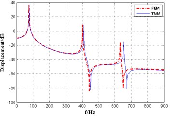
Fig. 3The transmitted power flow through the tail bearing
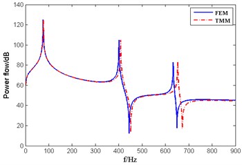
As can be seen from the graph, the results obtained by the two methods are in good agreement with each other, especially in the middle and low frequency bands below 300 Hz. The corresponding peak values are close to each other, and the peak frequency error is less than 3 %, which proves the accuracy of the transfer matrix method.
3. Analysis of the influence of structural parameters on the inherent characteristics of shafting flexural vibration
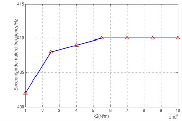
The mass of the propeller, the stiffness of the tail bearing and the front bearing have an important effect on the inherent characteristics of the flexural vibration of the shafting. Under the condition that other parameters are invariable, one kind of structural parameters is changed, and the influence on the natural frequency of the flexural vibration of the shafting was analyzed by using the transfer matrix method. The results are shown in Table 3 and Figs. 4-7.
Table 3Influence of propeller mass variation on natural frequency of shaft bending vibration
Natural frequency order | First order | Second order | Third order |
m1=4 kg | 93 | 414.28 | 653.5 |
m1=5 kg | 86.94 | 411.84 | 653.1 |
m1=6 kg | 81.93 | 409.98 | 652.81 |
m1=7 kg | 77.69 | 408.53 | 652.58 |
m1=8 kg | 74.04 | 407.37 | 652.39 |
m1=9 kg | 70.87 | 406.4 | 652.2 |
m1=10 kg | 68.07 | 405.61 | 652.12 |
Fig. 4Influence of stiffness of tail bearing on first order natural frequency
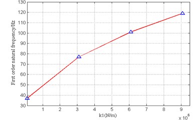
Fig. 5Influence of stiffness of tail bearing on second order natural frequency
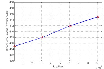
Fig. 6Influence of stiffness of front bearing on first order natural frequency
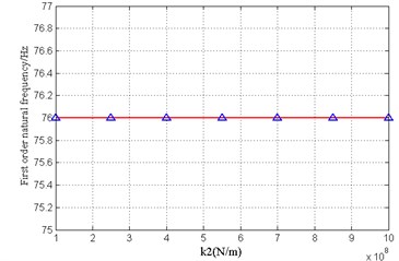
Fig. 7Influence of stiffness of front bearing on second order natural frequency
As can be seen from the calculation results:
(1) The sensitivity of each mode frequency to the propeller mass change is different. The change of the mass of the propeller mainly affects the first two modes of the bending vibration of the shaft system, especially the first order. With the increase of propeller mass, the corresponding modal frequency decreases gradually.
(2) Similar to the mass change law, the sensitivity of the modal frequencies to the stiffness of the tail bearing and the front bearing is also different. The stiffness of the tail bearing mainly affects the first two natural frequencies of the shafting; The first order mode frequency does not change with the front bearing stiffness changes, the second order modes show the “rising-stabilize” rule with the change of the front bearing stiffness.
4. Optimization design of shafting bearing parameters
At present, the optimization design method has been widely used in the field of structural dynamics design. The optimization design method is based on the mathematical optimization theory, and is used to find the best design scheme with various optimization program. Here on the basis of the original shaft model, considering all the bearing support, selecting the bearing stiffness as the optimization parameters and selecting the sum of the power flow of each bearing of the shafting system as the optimization objective, use MATLAB and Isight optimization software to optimize and use ABAQUS software to verify the effect of optimization. The optimization problem is described as follows:
(1) Optimization design variables: k1∈[100000.0,9000000.0],k2∈[1.0E8,1.0E9],k3∈[1000000.0,1.0E8].
(2) Optimization goal: Minimum the sum of the transmitted vibration power flow of each bearing support within 1-850 Hz frequency band:
(3) Optimization algorithm: Pointer optimizer provided by Isight software.
The optimization results are shown in Tables 4, 5. As can be seen from the results that through the optimization design, the vibration power flow passing through the tail bearing is decreased by 8.40 dB, and the total vibration power flow of each bearing support is decreased by 8.31 dB, and the effect is very significant.
Table 4Comparison of initial and optimized values
Initial value (N/m) | Optimization value (N/m) | |
k1 | 3000000 | 100000.0 |
k2 | 2.5E8 | 1.0E9 |
k3 | 6000000 | 1000000.0 |
Table 5Vibration power flow of each bearing
Before optimization | After optimization | Vibration energy change | |
Tail bearing | 3.5115 W | 0.5071 W | –8.40 dB |
Front bearing | 0.0500 W | 0.0186 W | –4.29 dB |
Spline shaft front end support | 0.00058 W | 0.0002 W | –4.34 dB |
Sum | 3.5620 W | 0.5260 W | –8.31 dB |
5. Conclusions
To study the problem of flexural vibration of the shafting system for the underwater vehicle with relatively small scale, the transfer matrix method is used to solve the displacement response and the vibration power flow of each bearing and compare with the finite element method to prove the accuracy of the method. With the convenience of transfer matrix method, the influence of the propeller mass and the bearing stiffness on the inherent characteristics of the shafting vibration was studied, on this basis, the total power flow transmitted to each bearing is optimized as the optimization target, and the stiffness of each bearing is optimized. This method can be used as a reference for the design of low noise propulsion shafting.
References
-
Xie Jirong, Wu Yousheng, Shen Shungen, et al. Transmission character of propeller excitation through shaft-line system to hull. Shipbuilding of China, Vol. 52, Issue 1, 2011, p. 80-89.
-
Li Quanchao, Yu Qiang, Liu Wei, et al. Effect of supporting parameters on marine shaft vibration characteristics. Ship Science and Technology, Vol. 38, Issue 6, 2016, p. 101-104.
-
Wu Xianjun, Zhu Shijian. Calculation technique of vibration power flow based on finite element analysis and its application in the isolation system optimization. Journal of Ship Mechanics, Vol. 9, Issue 4, 2005, p. 138-145.
-
Li Haifeng, Lou Jingjun, Liu Xuewei, et al. Multi-objective design of ship propulsion shafting based on the multi-attribute decision making. Vibroengineering Procedia, Vol. 5, 2015, p. 95-100.

