Abstract
Torsional vibration dampers (TVDs) are essential components for reducing the torsional vibration of a vehicle power transmission system (VPTS). This paper presents a new parameter optimization method for designing TVDs. The method combines the modal inertia and energy methods by adjusting the modal inertia method using an adjustment factor that is optimized using the energy method. The optimization of TVD parameters seeks to minimize the maximum torsional elastic potential energy of the rear axle near the resonance speed, so that the design variables can be optimized by a manual search process. The proposed method is employed to optimize the parameters of single-stage, two-stage parallel, and two-stage series TVDs coupled to a model VPTS. The damping effects of TVDs optimized by the modal inertia method, the energy method, and the proposed method were compared and analyzed, and the calculation efficiencies of the methods were evaluated. Results show that the proposed method provides better damping effects than the modal inertia method, and also provides far better computing efficiency than the energy method.
1. Introduction
Torsional vibration is a significant type of vibration that generally occurs in vehicle power transmission systems (VPTSs). Severe torsional vibration can greatly affect not only the driving comfort of a vehicle, but also the durability of vehicle components. In addition, the noise, vibration, and harshness (NVH) performance requirements of vehicles are subject to increasingly severe constraints, and commonly employed clutch torsional vibration dampers (TVDs), which are relatively inexpensive, may not conform to modern damping requirements. Moreover, dual mass flywheel type TVDs, which provide better NVH performance, are too expensive for use in economical passenger vehicles. As a result, equipping VPTSs with economical and suitably high-performance TVDs has become increasingly urgent.
From a design perspective, TVDs provide a better damping effect with increasing moment of inertia (abbreviated henceforth as inertia) under optimally tuned conditions [1], and under constant inertia conditions, the damping effect can be improved by dividing a single-stage TVD into a multi-stage TVD comprising some number of stages [2]. However, providing an ever-increasing inertia requires increasing the mass of the components, which runs counter to the requirements for designing lightweight vehicles. In addition, increasing the number of TVD stages generally increases the costs, and each TVD stage requires additional space, which introduces additional design and installation challenges. From this perspective, improving current design optimization methods provides a necessary avenue for designing relatively low cost TVDs that meet both design specifications and damping performance requirements.
Current TVD designs have widely employed rubber components due to their low cost and convenience. At present, comprehensive investigations have been conducted to optimize and match the kinetic parameters of rubber TVDs [2-7]. However, these investigations have mainly focused on suppressing the torsional vibrations of crankshafts. The operational principles of TVDs are similar to those of dynamic vibration absorbers (DVAs) and tuned mass dampers (TMDs), where a matched TVD facilitates anti-resonance in the VPTS, and greatly reduces vibration at the nature frequency. Nonetheless, intense vibration may occur in the TVD.
Research regarding the vibration suppression of undamped and damped systems with a single degree of freedom (SDOF) have been well-established, and evaluation criteria have primarily included the suppression of their vibration amplitudes (H∞) [8], nonlinear responses [9], energy over their entire frequency range (H2) [10], transient responses [11] and their accelerations [12], and the suppressed frequency bandwidth and stability of the main system [13]. However, studies regarding the vibration suppression of systems with multiple degrees of freedom (MDOF) started relatively late. Lagrange’s interpolation algorithm has been utilized to calculate the system transfer function [14], and optimization was conducted using the damped least square feasible direction method. However, only dynamic systems with no more than 8 degrees of freedom (DOF) could be effectively studied due to the poor computing power at that time and the limited calculation accuracy of the Lagrange interpolation algorithm. More recently, single or multiple vibration modes of a main system were suppressed by rationally optimizing the parameters of one or more DVAs according to a minimum power flow criterion [15]. Ozer and Royston [16] employed invariant point theory developed by Den Hartog for undamped MDOF systems to establish equations for the optimal parameters of DVAs through Sherman-Morrison matrix inversion theory. Thus, a semi-analytical optimal design method was developed. Ozer and Royston [17] again utilized matrix inversion theory to further investigate suppressing the vibrations of a damped MDOF system by optimizing the parameters of DVAs based on the weighted and minimized responses of SDOF or more DOF. Vakakis and Paipetis [18] utilized the polynomial method to minimize the transmissibility between two DOF to optimize the parameters of DVAs in an undamped MDOF system. Kitis et al. [19] proposed a method for optimizing the parameters of dual DVAs by minimizing the transmissibility between two DOF for a damped MDOF system. Cunniff [20] employed the Newton iteration method to search the maximum vibration responses of a main system, and the optimal parameters of DVAs were obtained by optimization using the quasi-Newton Method. Marano et al. [21] achieved multi-objective optimization by minimizing the maximum standard deviation of the acceleration of a SDOF and the failure probability of TMDs in damped MDOF systems. Lavan and Daniel [22] proposed a fast-converging and efficient method to minimize the total mass of multiple TMDs, and the allowable acceleration of each DOF was employed as a constraint for the suppression of multiple vibration modes in three dimensions for irregularly shaped buildings (an MDOF system).
Regarding the parameter optimization of TVDs for systems with MDOF, we note that, while minimizing the vibration amplitude peak of a SDOF can certainly reduce the vibrational energy of a main MDOF system, the optimum damping effect of TVDs on the other DOF cannot be assured. In addition, minimizing the sum of the vibration amplitude peaks of all DOF will certainly suppress the vibration of every SDOF; however, phase differences between each SDOF will prevent each SDOF from simultaneously attaining a maximum response. Therefore, this method cannot guarantee the full absorption of the vibrational energy of the entire system over any single period of oscillation.
Currently, the modal inertia and energy methods are most widely employed for the parameter optimization of TVDs when the vibration control of the overall VPTS or several DOF is taken as the evaluation criterion. According to Den Hartog’s optimally tuned condition, an MDOF system in the modal inertia method is equivalent to a modal system based on the mode shape employed to match its TVD, and an analytical solution can be obtained efficiently without calculating vibration responses [2, 23]. However, the influence of damping effects between DOF is not taken into account, which is not appropriate for a damped MDOF system such as a VPTS. Therefore, the TVD parameters obtained by the modal inertia method does not represent an optimal solution when damping effects are taken into account. In contrast, the energy method considers the influence of damping by means of calculating responses. However, while this provides an optimal solution when damping effects are taken into account, it does so with a much lower computational efficiency. As a result, obtaining an optimal solution requires considerable time, particularly a multi-stage TVD resonating on a main system with a large number of DOF.
In this paper, we combine the advantages of the modal inertia and energy methods and mitigate their disadvantages by adjusting the modal inertia method using an adjustment factor that is optimized using the energy method. Our work is based on a modeled VPTS of a front-engine, rear-drive vehicle. Through the proposed approach, a reasonable matching between a TVD and the VPTS are realized, and the torsional vibration amplitude and maximum torsional elastic potential energy (TEPE) of the VPTS are reduced.
2. MDOF torsional vibration model of a VPTS
Due to the complicated structure of a VPTS, the lumped mass method was utilized to simplify the torsional vibration model, which means that a forced vibration model was established by taking the engine output torque as the excitation source. In accordance with the principle of simplification and equivalent calculation method [3], the inertia of each SDOF, the torsional stiffness, and damping coefficient beginning with the intermediate shaft of the gearbox were rendered equal to the engine crankshaft, depending on the transmission ratio of the gear wheels. Accordingly, a 39-DOF torsional vibration model was established, as shown in Fig. 1. The definitions of the inertia terms for the different components of the VPTS represented by each SDOF are listed in Table 1.
Fig. 1VPTS torsional vibration model
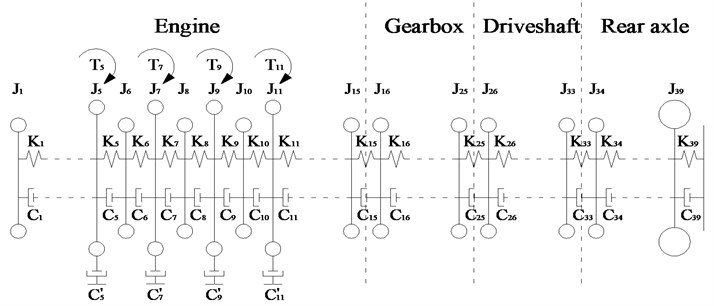
The torsional vibration equation of the VPTS is:
where θ, ˙θ, and ¨θ represent angular displacement, angular velocity and angular acceleration 39×1 column vectors, respectively. T represents the column vector of the excitation torque, i.e., T=[0,0,0,0,T5,0,T7,0,T9,0,T11,0,⋯,0]T39×1, and J, C, and K represent the 39×39 inertia matrix, the torsional damping matrix, and the torsional stiffness matrix, respectively, which are expressed as follows:
Table 1Definitions of the different DOF
Symbol | Definition |
J1 | Inertia of the torsion damper at the free end of the engine crankshaft |
J2, J3, J13, and J14 | Inertia values of the stepped shafts |
J4, J6, J8, J10, and J12 | Inertia values of the main journal |
J5, J7, J9, and J11 | Inertia values of the 4 cylinder crank-connecting rod mechanisms |
J15 | Inertia values of the flywheel and driving part of the clutch |
J16, J17, J18, and J19 | Inertia values of the driven part of the clutch and input shaft of the gearbox |
J20 and J21 | Inertia values of the intermediate shaft of the gearbox |
J22, J23, J24, and J25 | Inertia values of the output shaft of the gearbox |
J26 | Inertia of the front universal joint and internal spline |
J27 | Inertia of the front half shaft |
J28 | Inertia of the intermediate spline |
J29 | Inertia of the intermediate universal joint |
J30, J31, J32 | Inertia values of the rear half shaft |
J33 | Inertia of the rear universal joint |
J34 and J35 | Inertia values of the main reducer driving and driven bevel gear |
J36 | Inertia of the differential mechanism |
J37 and J38 | Inertia values of the two half-axles |
J39 | Equivalent inertia of wheels and the entire vehicle |
Ki (i= 1, 2, …, 38) | Torsional stiffness between various DOF |
K39 | Torsional stiffness of tires |
Ci (i= 1, 2, …, 38) | Torsional damping coefficient between various DOF |
C39 | Torsional damping coefficient of tires |
C'5, C'7, C'9, and C'11 | External damping coefficients of the 4 cylinder piston crank-connecting rod mechanisms |
The output torque of each cylinder can be presented according to a Fourier series expansion to determine each harmonic excitation torque. Considering that the firing order is 1-3-4-2, the output torque values of the four cylinders can be derived as follows:
Here, A0 represents the average output torque of a single cylinder, An represents the amplitude of the nth order torque, ω represents the excitation frequency, t is time, and φn represents the phase angle of the nth order torque of the first cylinder (n= 0.5, 1, 1.5, 2, …).
The harmonic superposition method was employed to solve for the vibration amplitude of each SDOF. As shown in Fig. 2, the vibration amplitudes at the input ends of the gearbox, driveshaft, and rear axle all peak at an engine speed of about 1500 rpm, which represents a resonance phenomenon in the VPTS. This phenomenon can be reduced by a TVD.
Fig. 2Amplitudes of different DOF
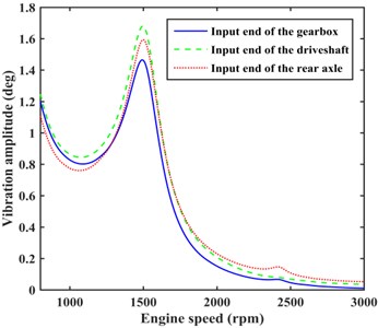
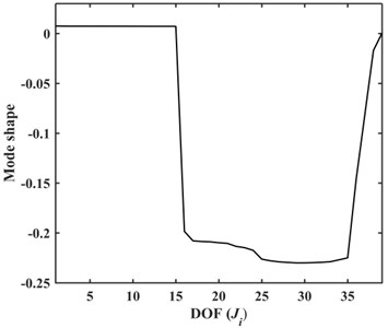
Fig. 3Third order mode shape of the VPTS
Prior to optimization, a natural characteristics analysis was firstly conducted for the torsional vibration model. Here, an undamped free vibration model is generally utilized to simplify the calculation:
The characteristic equation was solved to obtain the third order natural frequency (50.58 Hz) corresponding to the resonance rotation speed at about 1500 rpm. The corresponding mode shape is shown in Fig. 3, which indicates that the torsional vibration of the complete engine crankshaft (DOF J1-J15) is inconspicuous, the clutch (DOF J15 and J16) undergoes large deformation due to its low torsional stiffness, which is much less than that of the other shaft segments, the vibration enlarges continuously as the transmission power passes through the input shaft (DOF J16-J19), intermediate shaft (DOF J20 and J21), and output shaft(DOF J22-J25) of the gearbox, the complete driveshaft (DOF J26-J33) and main reducer (DOF J34 and J35) vibrate increasingly violently, and the vibration decreases rapidly as the transmission power passes through the differential mechanism (SDOF J36), half-axles (DOF J37 and J38), and reaches the tires (SDOF J39).
In an MDOF system, the SDOF having the largest amplitude is equipped with a TVD to absorb the greatest amount of vibrational energy. According to the vibration characteristics of the model VPTS and actual situations, a TVD can be optionally equipped at the back end (SDOF J32) of the driveshaft. The mechanical model is shown in Fig. 4, where J'tvd, K'tvd, and C'tvd represent the equivalent inertia, torsional stiffness, and torsional damping coefficient of the crankshaft for the TVD, respectively. Then, the torsional vibration equation is established as follows:
Fig. 4Mechanical matching model of the TVD
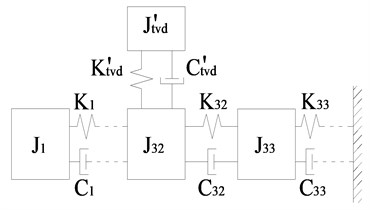
Fig. 5TVD and modal inertia
3. Description of modal inertia and energy methods
3.1. Modal inertia method
The modal inertia method regards the MDOF system as a SDOF system in the vibration mode according to the equivalent vibrational energy [23]. By assuming a harmonic solution θi=Θisin(ωt), where θi is the vibration response and Θi is the vibration amplitude of the ith DOF. Hence, the velocity of the ith DOF is ˙θi=Θiωcos(ωt), and the kinetic energy of the MDOF system is TM=12∑39i=1Ji˙θ2i. Assuming an installation of the TVD on the jth DOF, and the motion of the jth DOF can be replaced by SDOF Js, such that the kinetic energy is Tj=12Js˙θ2j, assuming that Tj=TM, the equivalent inertia (modal inertia) is obtained as follows:
The relative vibration amplitude of each SDOF in the vibration mode for an undamped system can be represented by the mode shape [y1⋯yj⋯y39]T, which yields:
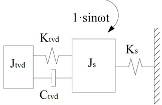
A mechanical model of Js subjected to unit harmonic excitation coupled to a TVD is shown in Fig. 5, where the modal stiffness (Ks) can be calculated by the expression ωn=√Ks/Js, and ωn represents the natural frequency of the main system. The optimal torsional stiffness (Ktvd) and damping coefficient (Ctvd) of a single-stage TVD can be solved from analytic solutions obtained in accordance with Den Hartog’s optimally tuned formula [2, 3]:
where: ωa=√Ktvd/Jtvd represents the natural frequency of the TVD, μ=Jtvd/Js represents the ratio of the inertia of the TVD to Js; and Cc=2Jtvdωn represents the critical damping coefficient.
3.2. Energy method
In this method, the torsional stiffness and torsional damping coefficient of the TVD are taken as design variables, and as the constraint condition, the torsional vibration torque of each shaft section in the torsional vibration system should be less than the corresponding allowable torque. Because the torsional vibration of the rear axle dominates the overall NVH performance, the objective function seeks to minimize the maximum TEPE of the rear axle (beginning with component i= 33), which is equipped with a TVD. The optimization model is as follows:
Here, Fm is the maximum TEPE of the rear axle when ω=ωm, E is the maximum TEPE of the rear axle near the resonance speed. we also note that the corresponding frequency ω near the resonance speed was divided into m – 1 equal parts, i.e., ω1,ω2,…,ωm, which represents an even number of points; and Tm is the time period of the torsional vibration system when ω=ωm. The crankshaft completes two revolutions during a single excitation period, and the 0.5th order excitation has the largest time period in multiple frequency excitation; therefore Tm=4π/(0.5ωm). Finally, G(Ktvd,Ctvd) represents the inequality constraints. The responses of various-order excitation torque are superimposed to obtain the response of each SDOF based on the linear superposition principle:
where Xn represents the column vector of the vibration amplitudes subjected to the nth order excitation torque of the torsional vibration system. The corresponding steady-state solution of vibration responses is given by the imaginary part of Eq. (15).
4. The proposed method
To consider the damping effect between various shaft sections, the MDOF system can be equivalent to a SDOF system, as shown in Fig. 6, in which Cs is the modal damping coefficient. The value of Cs can be obtained in accordance with the equal dissipated energy for the MDOF system and the equivalent SDOF system in the vibration mode. The dissipated energy of the MDOF system in the vibration mode can be obtained as follows:
+C'9πωnΘ29+C'11πωnΘ211.
The dissipated energy of the SDOF system is given by:
By equating W1 and W2, we obtain the expression for Cs:
Fig. 6Equivalent damped SDOF system
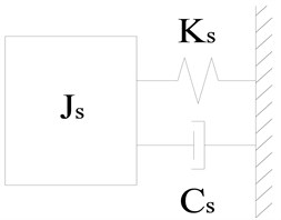
Fig. 7TVD and an equivalent damped SDOF
As for a damped MDOF system subject to a harmonic torque, we assume a harmonic solution θi=Θisin(ωt+αi), where αi is the phase angle of the ith DOF. Hence, the velocity of the ith DOF is ˙θi=ωΘicos(ωt+αi), and the kinetic energy of the MDOF system is TM=12∑39i=1Jiθ2i. Assuming that the TVD is installed on the jth DOF, and the motion of the jth DOF can be replaced by a vibrational SDOF. On the basis of energy-equivalence principle described in section 3.1, the inertia of the SDOF can be obtained as follows:
When ω=ωn, discrepancies develop between the actual relative vibration amplitude relationships of various DOF and the mode shape, and the damping effect may lead to a decrease in the relative vibration. By assuming that the jth DOF has the largest vibration amplitudes in undamped and damped MDOF systems, we obtain:
The viscous damping effect induces phase differences between various DOF, and we note from Eq. (19) that Jω varies with respect to t during a period of oscillation (i.e., T=2π/ω). Consequently, the TVD optimized by the modal inertia method is inaccurate from the perspective of equivalent energy.
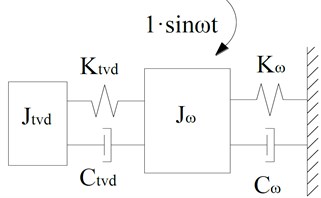
In Fig. 7, we assume that there is a set of optimal parameters of Jω, Kω, and Cω can provide the TVD with best damping effect for MDOF system. Assume that the relationship of Jω and Js is given by:
where β is defined as adjustment factor. To ensure that ωn and damping ratio (Cs/(2Jsωn)) do not change, the Ks and Cs are also adjusted proportionately with respect to Js, thus:
For an undamped MDOF system, the TVD with parameters optimized by the modal inertia method splits the original energy peak of the main system into two smaller and equal peaks. However, for a damped MDOF system, the modal inertia method cannot provide two smaller energy peaks of equal height. In Fig. 7, Jω may be considered as being adjusted properly to provide two smaller energy peaks of the same height. A TVD is employed to absorb excess system energy, and the modal inertia is adjusted to absorb more energy. From this perspective, the appropriate adjustment factor β can be optimized by minimizing the maximum TEPE of the rear axle near the resonance speed.
For the optimization of TVD parameters in Fig. 7, a numerical optimization method is generally employed to minimize the maximal vibration amplitude of Jω, thus to ensure that all peak values are of equivalent heights. Through calculation, the expression for the parameters of the TVD in terms of β can be obtained:
The substitution of Eq. (23) into Eq. (14) yields the following TEPE optimization model for β:
5. Optimization of β
5.1. Optimization of single-stage TVD parameters
Based on the VPTS torsional vibration model presented in Section 2, the value of Js calculated by Eq. (12) is 0.0058 Kg·m², and the value of Cs calculated by Eq. (18) is 0.1159 N·m·s/rad. By assuming that the value of μ is 0.3. The TVD parameters were calculated using Eq. (23) and the maximum TEPE near the resonance speed of the rear axle was calculated by Eq. (24), and the results are listed in Table 2 for different values of β. The maximum TEPE decreases continuously while β increases from 1 to 1.9, and increases when β= 2.0. Thus, we preliminarily conclude that the optimal β is close to 1.9. The maximum TEPE was calculated for β values 1.89 and 1.91, and the maximum TEPE was found to obtain a minimum when β= 1.9.
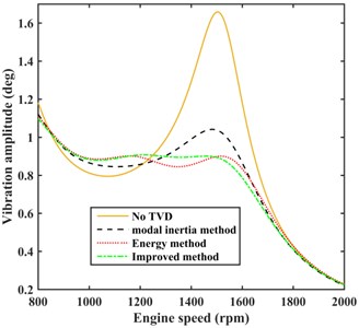
The energy method given by Eq. (14) provides the following optimized TVD parameters: Ktvd= 121.4572 N·m/rad, Ctvd= 0.1840 N·m·s/rad, and the maximum TEPE is 0.0235 J. The optimized parameters obtained using the modal inertia method, the energy method, and the proposed method were substituted into Eq. (10), and the calculated vibration amplitudes at the input end of the rear axle (main reducer) are shown in Fig. 8. The figure indicates that the amplitude of the damped system employing TVD parameters optimized by the proposed method is further reduced at approximately 1500 rpm and increases slightly between 1000-1300 rpm compared with the amplitude when employing the TVD parameters optimized by the modal inertia method. On the other hand, the amplitude increases slightly between 1200-1500 rpm and decreases slightly between 1500-1700 rpm and is essentially equivalent at all other speeds compared with the amplitude when employing the TVD parameters optimized by the energy method.
Table 2Optimized single-stage TVD parameters obtaining the smallest maximum TEPE value
β | Ktvd (N·m/rad) | Ctvd (N·m·s/rad) | Maximum TEPE (J) |
1 | 100.0081 | 0.2347 | 0.0314 |
1.2 | 106.9978 | 0.2396 | 0.0297 |
1.4 | 113.6095 | 0.2335 | 0.0266 |
1.6 | 119.0559 | 0.2258 | 0.0258 |
1.8 | 123.5345 | 0.2199 | 0.0244 |
1.9 | 125.5297 | 0.2161 | 0.023765 |
2.0 | 127.3565 | 0.2129 | 0.0241 |
1.89 | 125.3525 | 0.2160 | 0.023781 |
1.91 | 125.7167 | 0.2158 | 0.023801 |
The proposed method obtains a better optimal solution than the modal inertia method, and within a much shorter time using a manual search of the adjustment factor than the energy method. From comparison tests, the proposed method is found to require less than 2 min of the computing time, but the energy method consumes 30 min. As such, the computing efficiency increased greatly while simultaneously ensuring a near optimal damping effect.
Fig. 8Vibration amplitudes at the input end of the rear axle for the undamped VPTS and damped VPTS employing TVD parameters optimized by the various methods
5.2. Optimization of parameters for two-stage parallel and series TVDs
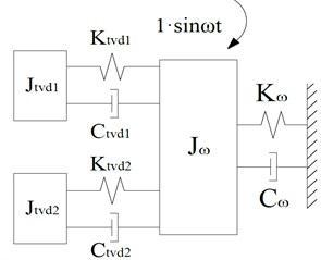
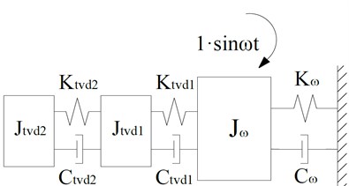
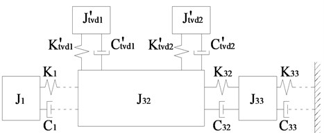
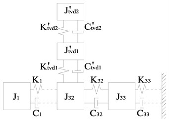
In addition to single-stage TVDs, the proposed method is also applicable for the optimization of parameters for multi-stage TVDs. For enhancing the damping effect, a single-stage TVD may be converted into a two-stage parallel or series TVD, whose mechanical models are shown in Fig. 9. In contrast, the mechanical model of the matched MDOF system is shown in Fig. 10, whose torsional vibration equation is:
In Fig. 9, a two-stage TVD will induce two new resonance frequencies near the original resonance frequency of Jω. The presence of three close peaks tends to trap the optimization results in local attractive basins, which results in a less than optimal damping effect. A comparisons of the damping effects of the two-stage TVDs with parameters optimized using the local optimization solver and the global optimization solver are shown in Fig. 11 when β= 1, where the excited frequency ratio represents ω/ωn, and the vibration amplitude ratio represents the ratio of the vibration amplitude of Jω to its static deflection (1/Ks).
Fig. 9Mechanical models of two-stage TVDs and an equivalent damped SDOF
a) Two-stage parallel TVD
b) Two-stage series TVD
Fig. 10Mechanical models of the matched MDOF system including a two-stage TVD
a) Two-stage parallel TVD
b) Two-stage series TVD
Fig. 11Comparison of damping effects for the two-stage TVDs optimized by the local and global optimization solvers
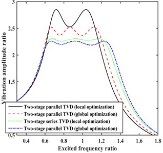
Fig. 11 shows that only two peaks are obtained due to the local optimization of the two-stage parallel TVD, which represents a much lower damping effect than when using the global optimization solver, and the damping effect of the two-stage series TVD with parameters optimized using the local optimization solver is slightly weaker than that when employing the global optimization solver. It must be noted that, the results of two-stage TVD parameter local optimization are strongly correlated to the initial values selected, and thus a global optimization solver must be employed.
The optimization strategy is as follows: the total inertia of the two-stage TVDs remains unchanged and equal to the inertia of a single-stage TVD for optimization each time the value of β is changed. The optimal parameters of the two-stage parallel and series TVDs and the maximum TEPE obtained based on Eq. (25) for different values of β are listed in Tables 3 and 4, respectively. It must be noted that, the torsional damping coefficient of rubber is generally between 0.05-0.4 N·m·s/rad, which should be the range of damping coefficient for optimization.
For the two-stage parallel TVD, the maximum TEPE decreases continuously with increasing β from 1 to 2.1, and then increases for β= 2.2. Thus, we preliminarily conclude that the optimal value of β is close to 2.1. The maximum TEPE was calculated for β ranging from 2.09 to 2.06, and the maximum TEPE obtained a minimum value when β= 2.07.
For the two-stage series TVD, the maximum TEPE decreases continuously with increasing β from 1 to 1.9, and then increases for β= 2.0. Thus, we preliminarily conclude that the optimal value of β is close to 1.9. The maximum TEPE was calculated for β ranging from 1.89 to 1.87, and the maximum TEPE obtained a minimum value when β= 1.88.
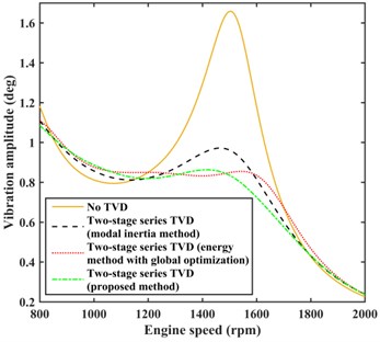
The damping effects of the TVD with parameters optimized by the modal inertia method and the proposed method were compared, and the vibration amplitudes at the input end of the rear axle are shown in Fig. 12. The figure indicates that the amplitude near 1500 rpm has decreased considerably, but a small increase is observed in the range 1000-1250 rpm compared with the damping effect of the TVD with parameters optimized by the modal inertia method. The improvement in the damping effect of the two-stage series TVD is particularly obvious for a very small increase at engine speeds below the resonance speed.
The following optimization model is employed for optimizing the parameters of a two-stage TVD using the energy method:
Table 3Optimized results of the two-stage parallel TVD shown in Fig. 9(a)
β | Ktvd1 (N·m/rad) | Ctvd1 (N·m·s/rad) | Ktvd2 (N·m/rad) | Ctvd2 (N·m·s/rad) | μ1 (Jtvd1/Js) | Maximum TEPE (J) |
1 | 56.4522 | 0.0841 | 51.1461 | 0.0981 | 0.1123 | 0.0295 |
1.3 | 63.8788 | 0.0804 | 55.1059 | 0.0869 | 0.1202 | 0.0263 |
1.6 | 66.3371 | 0.0742 | 60.1855 | 0.0835 | 0.1198 | 0.0248 |
1.9 | 68.6973 | 0.0700 | 63.4844 | 0.0798 | 0.1211 | 0.0236 |
2.0 | 69.9358 | 0.0696 | 63.9309 | 0.0777 | 0.1227 | 0.0233 |
2.1 | 70.5329 | 0.0688 | 64.7748 | 0.0768 | 0.1231 | 0.0232 |
2.2 | 64.1367 | 0.0571 | 71.5671 | 0.0843 | 0.1093 | 0.0236 |
2.09 | 69.3900 | 0.0669 | 65.6768 | 0.0779 | 0.1207 | 0.0231 |
2.08 | 72.4229 | 0.0722 | 62.8787 | 0.0744 | 0.1274 | 0.023090 |
2.07 | 72.3477 | 0.0721 | 62.8873 | 0.0739 | 0.1271 | 0.023077 |
2.06 | 70.1110 | 0.0691 | 64.6312 | 0.0773 | 0.1226 | 0.023106 |
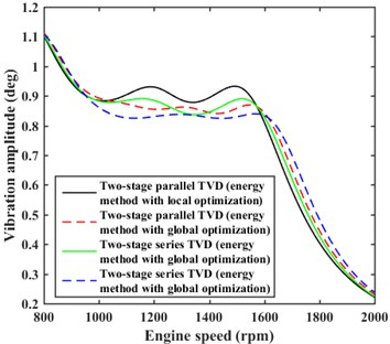
The problem of local convergence also exists when using the energy method. The tendency for the optimization results to become trapped in local attractive basins can observed in Fig. 13, where the damping effects of the two-stage TVDs with parameters optimized using the energy method with local optimization may be weaker than the damping effects obtained when the parameters are optimized with global optimization. Thus, a global optimization solver must again be employed, and the optimization results are listed in Table 5.
Table 4Optimized results of the two-stage series TVD shown in Fig. 9(b)
β | Ktvd1 (N·m/rad) | Ctvd1 (N·m·s/rad) | Ktvd2 (N·m/rad) | Ctvd2 (N·m·s/rad) | μ1 (Jtvd1/Js) | Maximum TEPE (J) |
1 | 129.6381 | 0.0637 | 26.7104 | 0.1074 | 0.2008 | 0.0286 |
1.3 | 137.5174 | 0.0508 | 26.3674 | 0.0879 | 0.2156 | 0.0253 |
1.6 | 142.4851 | 0.0508 | 24.6342 | 0.0716 | 0.2288 | 0.0233 |
1.9 | 146.2299 | 0.0506 | 22.9260 | 0.0606 | 0.2380 | 0.0219 |
2.0 | 147.2810 | 0.0506 | 22.4464 | 0.0576 | 0.2405 | 0.0220 |
1.89 | 146.1278 | 0.0506 | 23.0416 | 0.0610 | 0.2377 | 0.021908 |
1.88 | 145.9189 | 0.0500 | 22.7837 | 0.0606 | 0.2378 | 0.021885 |
1.87 | 145.9189 | 0.0500 | 22.7837 | 0.0606 | 0.2377 | 0.021915 |
Table 5TVD parameter results optimized by the energy method with global optimization
Ktvd1 (N·m/rad) | Ctvd1 (N·m·s/rad) | Ktvd2 (N·m/rad) | Ctvd2 (N·m·s/rad) | μ1 (Jtvd1/Js) | Maximum TEPE (J) | |
Two-stage parallel TVD | 54.1103 | 0.0503 | 64.0730 | 0.0931 | 0.1087 | 0.0228 |
Two-stage series TVD | 125.6472 | 0.0546 | 16.8626 | 0.0763 | 0.2330 | 0.0216 |
Fig. 12Comparison of damping effects for the modal inertia and proposed methods
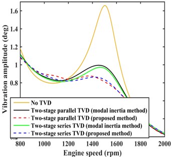
Fig. 13Comparison of damping effects for the energy method with local and global optimizations
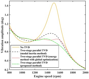
The damping effects of the two-stage parallel and series TVDs optimized by the modal inertia method, the energy method with global optimization, and the proposed method were compared, and the vibration amplitudes at the input end of the rear axle are shown in Fig. 14. We can observe that the energy method with global optimization provided a slightly better damping effect than the proposed method in the 1300-1500 rpm range, although the proposed method generally produced a better damping effect for engine speeds greater than 1500 rpm.
The energy method with global optimization has very low computing efficiency, particularly for the large number of DOF of the main system, such that the method requires about 4 h computation time when the 2nd and 4th order torques which are only considered as the main causes for torsional vibration. The multiple design variables must be optimized by the energy method using a complex model like that shown in Fig. 1, for which the vibration responses must be solved. In contrast, the proposed method translates the multiple design variables into a single optimal design variable β obtained by global optimization on the basis of the simplified model in Fig. 9, which provides low complexity and high computing efficiency, and requires about only 10 min. In addition, it is far more efficient to apply global optimization to the model in Fig. 9 than in the VPTS model shown in Fig. 1.
Fig. 14Comparison of damping effects by different methods
a) Two-stage parallel TVD
b) Two-stage series TVD
6. Practical applicability of the proposed damping technique
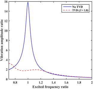
The proposed method can be improved at the condition that the natural frequency of the vibration system closes to the boundaries of excitation frequency domain. Fig. 15 shows a damped SDOF model consists of Js, Ks, and Cs, and subjected to unit harmonic excitation coupled to a TVD. If ωn closes to the lower bound of ω, the height of the right peak can be adjusted lower than that of the left peak, the reason for this is that the probability of ω reaches the left peak frequency is largely less than that of the right peak.
Fig. 15TVD and a damped SDOF system
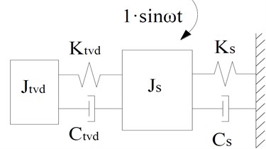
Fig. 16TVD parameters optimization for the conditions that ωn close to boundaries of ω
a)ωn close to lower boundary
b)ωn close to upper boundary
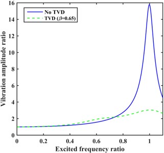
Through comparative calculation, the value of β could be selected as 1.8. Then the graph of vibration amplitude ratio of Js against ω/ωn is shown in Fig. 16(a). In contrast, if ωn closes to the upper bound of ω, the height of the left peak can be adjusted lower than that of the right peak, and β could be selected as 0.65. Then the vibration amplitude graph is shown in Fig. 16(b).
The modal inertia method and the energy method cannot adjust the heights of the two peaks in these special conditions, and the proposed method after improvement can provide different peak heights as required by adjusting β.
7. Conclusions
By considering the inherent torsional vibration characteristics of the entire VPTS as the starting point, we combined the modal inertia method with the energy method to propose a new method for optimizing the parameters of a TVD. These three methods were applied for optimizing the parameters of single-stage, two-stage parallel, and two-stage series TVDs for the model VPTS shown in Fig. 1. The proposed method provides peak values of equivalent heights (excluding the special conditions described in the research extension) in the energy curve by adjusting β, and the local convergence is not existed when the TVD parameters listed in Tables 3 and 4 are in the condition of global convergence solutions. In addition, the proposed method has been accepted by the cooperative enterprise, and the production and performance test of TVDs are now being considered. Due to limited space, these contents will be discussed in the following research.
The main conclusions are as follows:
1) The vibration amplitude at the input end of the rear axle for TVD parameters optimized using the proposed method may increase slightly for engine speeds less than the original resonance speed relative to that obtained for TVD parameters optimized using the modal inertia method. Moreover, the vibration amplitude growth rate may rise gradually along with increasing β.
2) The method proposed in this paper combines the advantages of high computing efficiency provided by the modal inertia method and the excellent damping effect of the TVD using parameters optimized by the energy method with global optimization. On the other hand, the disadvantages of insufficient damping effect provided by the TVD using parameters optimized by the modal inertia method and the poor computing efficiency of the energy method with global optimization are both avoided. These merits make the proposed method very practical and effective in engineering applications, which can be extended to the optimal design of DVAs and TMDs coupled to an MDOF system.
3) The merits of the proposed method are increasingly apparent as the number of DOF of the system increases, particularly when employed for the parameter optimization of multi-stage TVDs coupled to the system. However, the advantages are not particularly obvious when a single-stage TVD is coupled to a system with a smaller number of DOF.
References
-
RaoSingiresu S. Mechanical Vibrations. Fifth Edition, Prentice Hall, 2011.
-
Shangguan Wenbin, Pan Xiaoyong Multi-mode and rubber-damped torsional vibration absorbers for engine crankshaft systems. International Journal of Vehicle Design, Vol. 47, 2008, p. 176-188.
-
Nestorides E. J. A Handbook on Torsional Vibration. Cambridge, 2011.
-
Londhe A., Yadav Vh. Design and optimization of crankshaft torsional vibration damper for a 4-cylinder 4-stroke engine. SAE Paper, 2008, https://doi.org/10.4271/2008-01-1213.
-
Ebrahimi M., Jamil Z. M., Wood A. S. Optimum crankshaft damper selection. International Journal of Vehicle Noise and Vibration, Vol. 2, Issue 2, 2006, p. 111-124.
-
Mitianiec W., Buczek K. Interdependence of torsional vibration damper parameters on crankshaft's torsional vibrations. Journal of KONES Powertrain and Transport, Vol. 15, Issue 4, 2008, p. 351-358.
-
Homik W. Influence of temperature changes on torsional rigidity and damping coefficient of rubber torsional vibration damper. Transport Problems an International Scientific Journal, Vol. 6, Issue 1, 2011, p. 129-135.
-
Brown B., Singh T. Minimax design of vibration absorbers for linear damped systems. Journal of Sound & Vibration, Vol. 330, Issue 11, 2011, p. 2437-2448.
-
Viguié R., Kerschen G. Nonlinear vibration absorber coupled to a nonlinear primary system: A tuning methodology. Journal of Sound and Vibration, Vol. 326, Issues 3-5, 2009, p. 780-793.
-
Tigli O. F. Optimum vibration absorber (Tuned Mass Damper) design for linear damped systems subjected to random loads. Journal of Sound and Vibration, Vol. 331, Issue 13, 2012, p. 3035-3049.
-
Issa J. S. Reduction of the transient vibration of systems using the classical and a modified vibration absorber setup. Journal of Vibration and Control, Vol. 20, Issue 10, 2013, p. 1475-1487.
-
Yang P., Liu F., Liu Y., et al. Computer-aided design integration of a reinforced vibration isolator for electronic equipment’s system based on experimental investigation. Structural and Multidisciplinary Optimization, Vol. 35, Issue 5, 2008, p. 489-498.
-
Boroson E., Missoum S. Stochastic optimization of nonlinear energy sinks. Structural and Multidisciplinary Optimization, Vol. 55, Issue 2, 2017, p. 633-646.
-
Wang Zaishen, Liang Yanchun Damped least square feasible direction method for optimal design of physical parameters of mechanical systems. Proceeding of the International Conference on Mechanical Dynamic, ShenYang, 1987.
-
Wang Quanjuan, Huang Wenhua, Xia Songbo, et al. Vibration control of multi-degrees-of-freedom system with dynamic absorbers based on power flow. Chinese Journal of Acoustics, Vol. 3, 2003, p. 237-243.
-
Ozer M. B., Royston T. J. Application of Sherman-Morrison matrix inversion formula to damped vibration absorbers attached to multi-degree of freedom systems. Journal of Sound and Vibration, Vol. 283, Issue 3, 2005, p. 1235-1249.
-
Ozer M. B., Royston T. J. Extending Den Hartog’s vibration absorber technique to multi-degree-of-freedom systems. Journal of Vibration and Acoustics, Vol. 127, Issue 4, 2004, p. 341-350.
-
Vakakis A. F., Paipetis S. A. The effect of a viscously damped dynamic absorber on a linear multi-degree-of-freedom system. Journal of Sound and Vibration, Vol. 105, Issue 1, 1986, p. 49-60.
-
Cunniff P. F. Optimization of mechanical vibration isolation systems with multi-degrees of freedom. Journal of Sound and Vibration, Vol. 40, Issues 1-105, 1975, p. 117-1.
-
Kitis L., Wang B. P., Pilkey W. D. Vibration reduction over a frequency range. Shock and Vibration Digest, Vol. 89, Issue 4, 1983, p. 559-569.
-
Marano G. C., Quaranta G., Greco R. Multi-objective optimization by genetic algorithm of structural systems subject to random vibrations. Structural and Multidisciplinary Optimization, Vol. 39, Issue 4, 2008, p. 385-399.
-
Lavan O., Daniel Y. Full resources utilization seismic design of irregular structures using multiple tuned mass dampers. Structural and Multidisciplinary Optimization, Vol. 48, Issue 3, 2013, p. 517-532.
-
Seto K., Ookuma M., Yamashita S., et al. Method of estimating equivalent mass of multi-degree-of-freedom system. JSME International Journal, Vol. 30, Issue 1987, 268, p. 1638-1644.
Cited by
About this article
Dr. Xiaodong Tan handled the work of writing the full manuscript. Dr. Lin Hua worked out a technology scheme of using torsional vibration damper to solve the problem of torsional vibration of the vehicle, and revised the manuscript at last. Dr. Chihua Lu put forward the main innovation point, and implemented parameters optimization by MATLAB programming. Dr. Can Yang established the torsional vibration model. Dr. Yongliang Wang plotted the plane graphics, and organized the optimization data, and created the tables. Dr. Sheng Wang translated the Chinese manuscript into English.

