Abstract
The article presents equivalent mathematical models of a boring bar designed for deep boring, in a distributed and a discrete idealizations. A mathematical model describing coupled torsional and lateral vibrations of a boring bar is constructed in the form of a set of differential equations with lagging of the cutting process dynamics. A methodology for studying stability in small of the deep boring process using a characteristic quasi-polynomial is presented. The numerical-analytical results of the studies made it possible to discern stability regions in the parameter space of the model and to obtain relations for maximal cutting depth as a function of geometrical and technological parameters (stiffness, cutting velocity, feeding etc.) of the boring bar considered. It is noted that the obtained numerical-analytical results are in good agreement with experimental data.
1. Introduction
It is known [1] that console boring bars, being highly effective in boring deep orifices at specialized and general-purpose machines, possess low stiffness, reducing their vibration stability. As a result, a considerable number of works (see [1-16] and the related references) are dedicated to the numerical-analytical and experimental study of vibrations of console boring bars. This fact, undoubtedly, predetermined further priority of the issue of vibrostability in investigating the dynamics of machines. One of the labor-consuming operations in part cutting is boring deep orifices (orifices with the ratio of 5, where is orifice length and is its diameter). Due to insufficient stiffness of boring tools, the nonlinear relation between cutting force and cutting thickness and width, a phase characteristic of the cutting force, decrease of the cutting force with increasing cutting velocity and alteration of the front and rear angles of the tool in the presence of vibration, deep boring at specialized lathes at the most productive cutting regimes does not provide required quality parameters, leads to vibrations (torsional, lateral and longitudinal oscillations) and to decreasing the productivity of the machine, to premature wear of the tools or even to the damage of its cutting elements. This puts forward the issue of decreasing the vibration level accompanying deep boring, that is, determining technological parameters (feeding and cutting velocity, cutting depth and others) corresponding to the damping process of self-exciting torsional, lateral and longitudinal vibrations of the boring bar.
Works on deep drilling and boring are currently widely used in machine-tool industry and mechanical engineering [1-7], aircraft industry [8], in deep oil-well drilling etc. [8-17]. They review the main ways of deep boring, systematize the results of the studies and, based on it, present methodologies for designing highly productive tools and technologies.
Publications [1-7] mainly deal with experimental studies, in which particular factors causing self-excitation of vibrations in the metal cutting process were found out and investigated, and the results of experimental studies were given. In [1], the main ways of deep drilling and rough and finish boring are considered, and designs of highly-productive tools used in deep boring are described. The fundamentals of designing technological processes and tools providing high productivity and machining precision are presented. Vibration types and their causes are described, as well as the effect of the cutting process parameters and of the tools on vibration intensity, and the ways of reducing vibration intensity. Works [3-5] treat the issues of deep boring, depending on geometrical parameters, technological requirements it must comply with, and types of tools used to this end. It is shown that using a classification of applicability of tools will make it possible to reduce costs of production preparation and to increase labor productivity. In [7], the main issues of the dynamics of metal-cutting machinery are considered: equivalent and elastic systems, working processes, stability of dynamic systems, stationary and transient processes, forced vibrations in metal cutting.
Work [8] analyzes the causes of the development of self-excited oscillations in the process of deep boring when machining parts of aircraft engines, based on a 2D mathematical model and experimental data. Using numerical computations, it is found that changes in the cutting thickness resulting from the regenerative effect of “trail” machining produce the strongest effect on vibration intensity. Computational and experimental relations between vibration amplitude and cutting depth and feeding value are given. Work [9] presents experimental results on bending vibrations of a boring bar in idle running and cutting, which made it possible to establish relations between the vibration amplitude and damping value, stiffness, mass, cutting velocity and eigen-frequency of the boring bar. In [10-11], the results of choosing the cutting tool geometry and the cutting process for effective deep boring are presented. Works [12-13] analyze the cutting process on the macro and microscale levels in the process of deep-well boring. The experimental boring procedure is developed to study the effect of cutting and feeding velocity on the cutting process (as exemplified by machining the 18MND5 steel). Here, it is also found that cutting velocity affects vibrostability less than feeding velocity. In [14-16], the possibility of suppressing self-exciting vibrations in the drilling process, using parametric excitation and a specialized tool, is discussed. A two-mass system is considered, of which the main mass is excited by a self-exciting force (cutting force). The second mass, acting as a dynamic absorber, is attached to the main mass and, by varying the stiffness between the main mass and the absorber mass, represents parametric excitation. The experiments show that that vibration can be substantially suppressed with the parametric excitation effect. However, the interconnection and the effect of torsional, lateral and longitudinal vibrations on vibrostability in deep boring still remain insufficiently studied. To this end, the work presents equivalent mechanical models of a boring bar in a distributed and a discrete idealizations; a mathematical model is constructed in the discrete idealization, which describes the interrelation of torsional and lateral vibrations of the boring bar, representing a set of differential equations with lagging, describing the cutting process dynamics.
The results of the studies made it possible to discern regions of stability in the parameter space of the model and to obtain relations between maximal cutting depth and the lag value, geometrical and technological parameters (damping and stiffness coefficients, cutting and feeding velocity etc.) of the analyzed boring bar model. The results are shown to be in good agreement with the experimental data.
2. Description of the physical model
An equivalent mechanical model of a lathe designed for deep boring is exemplified in Fig. 1, where: (1) is shank of the boring bar with boring head (2), (3) is machined part, (4) is support, (5) is spindle head, (6) are slideways and (7) is bed frame.
Boring head (2) consists of a steel body housing cutters and feather keys, which enter the orifice being bored preloaded. Drilling and boring is done using single and multi-blade tools. The part is secured in the chuck, which rotates together with the spindle at n rpm, while the boring bar is secured to the support, which provides feeding at S mm/rev. An internal channel in the system is designed for supplying cutting fluid or for the exit of cutting chip, depending on the machining scheme. It is known [1] that the dominating vibrational element in the dynamic system is the boring bar shank. Besides, the body of the boring head experiences and translates onto the boring bar rather high loads resulting from cutting and friction along the slideways.
Fig. 1Equivalent mechanical model of a lathe
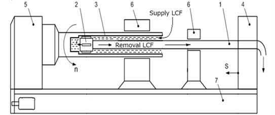
In deep boring, complex dynamic phenomena arise, which are connected with the metal cutting process and friction of the guiding elements against the surface of the machined part. The accompanying forces and moments depend on the angular rotation velocity of the part, technological parameters of cutting, tool geometry, cutting fluid, etc. Studying the dynamic of the boring bar, accounting for the interrelation of vibrations, poses certain difficulties, thus, the main currently available results on the study of vibration are presented separately for each of the three types of vibration (torsional, lateral and longitudinal).
There are a number of factors causing lateral self-vibrations: firstly, cutting velocity is normally in the range corresponding to the falling part of the cutting force/cutting velocity curve; secondly, variation of the cutting thickness, leading to variation of cutting force, which vary with a time lag relative to the variation of cutting thickness, thus exciting and enhancing self-oscillations. Torsional self-oscillations can be caused by the same factors as lateral ones.
To study the interrelated torsional and lateral vibrations, let us choose from the equivalent mechanical model of a lathe (Fig. 1) the most vibrational element the boring bar, with its equivalent mechanical model presented in Fig. 2.
Fig. 2Equivalent mechanical model of a boring bar in a distributed idealization
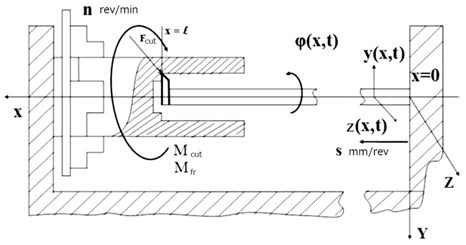
The boring bar in Fig. 2 is represented as an elastic rod with continuous mass distribution, accounting for its being rigidly secured in the support on one end and the specificity of the metal machining process on the other. It is assumed that the boring bar material is homogeneous and isotropic, and that the plane cross-section hypothesis holds. According to the designations used in Fig. 2, (, ), (, ) and (, ) describe torsional and lateral vibrations of the boring bar relative axes , and , respectively. In the process of deep boring, vibrations of the boring bar induce dynamic cutting forces , cutting moments and friction moments .
3. Mathematical model
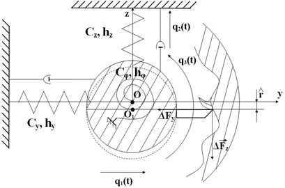
In constructing a mathematical model, it is assumed that a deep orifice is bored with a long hollow boring bar with a single-blade tool. As the boring bar is represented by an elastic rod (Fig. 2), one end of which is rigidly secured in the support and the other end is equipped with a cutting blade, which, in the process of machining with accompanying vibrations, experiences dynamic forces and a cutting moment, then, to simplify further investigations, the boring bar is substituted for by a material point with coordinate with reduced mass and moment of inertia (datum point ). The lateral and torsional stiffnesses of the boring bar are accounted for by introducing springs with the corresponding stiffness coefficients , and , respectively (Fig. 3).
Fig. 3Equivalent mechanical model of a boring bar in a discrete idealization. q1(t), q2(t) are displacements of the reduced mass relative coordinate axes y and z, and q3(t) is angular displacement relative axis x, perpendicular to plane (y, z)
3.1. Determining parameters of the equivalent mechanical model of the boring bar in a discrete idealization
Reduced mass , moment of inertia , stiffness coefficients , and are found from the equalities of kinetic and potential energies:
Of the initial (Fig. 2) and reduced (Fig. 3) models. In Eq. (1), the following expressions are given:
Are kinetic energies of the discrete model for lateral and torsional vibrations relative axes , and , respectively. Here , , , are the length, mass per unit length, density and polar moment of inertia of the boring bar.
Substituting:
Into Eq. (1) and keeping in mind that:
Are first eigenshapes of the lateral and torsional vibrations of the boring bar, and equating the corresponding kinetic energies, one obtains, after simple transformations, expressions for reduced mass and reduced moment of inertia as 0.24 ml, . It should be noted that such representation of (, ), (, ) and (, ) is possible, as numerous experimental studies testify to the fact [6] that self-excitation of lateral and torsional vibrations of the boring bar during deep boring takes place at the frequencies close to the first vibration eigen-frequencies of the boring bar.
To determine stiffness coefficients , and one has:
are potential energies of the distributed model for lateral and torsional vibrations, and:
are kinetic energies of the discrete model for lateral and torsional vibrations relative axes , and , respectively. Here, , , are bending and torsional stiffnesses of the cross-section of the boring bar.
Using Eqs. (1) and (2), the stiffness coefficients are found:
Energy dissipation coefficients of the discrete model , and can be found, using the following relations:
where , are first eigenfrequencies of the model, is logarithmic decrement of vibrations, as obtained based on the experimental curves of damping vibrations.
3.2. Equations of motion of the boring bar for boring deep orifices
To derive equations of motion, kinetic and potential energies of the equivalent mechanical model in its discrete idealization are written as:
Using second-kind Lagrange equations, Eq. (3) and linearized increments of projections of the dynamic cutting force and , the equations of motion in will be written as:
where , , , is outer radius of the boring bar, is static displacement of the reduced mass of the boring bar due to the effect of static cutting force in the process of boring, and are increments of projections of the dynamic cutting force on the axis of the coordinates, which are determined by dynamic forces induced by relative vibrations of the cutter and the part in the cutting zone at the moment, as well as by forces related with cutting the trail, and can be written with the account of the main cause of self-excitation of vibrations, lagging, in the following form [6, 7]:
where , are dynamic characteristics of cutting, and is overlapping coefficient ().
The experimental studies show that [1, 6] static displacement of the reduced mass under the effect of static force is about 2 mm, hence, it can be written that . Thus, to simplify the further analysis, item in the expression for the cutting moment increment will be omitted.
3.3. Method of D-decomposition using one complex parameter
The problem of analyzing stability of equilibrium states of linearized systems with lagging is reduced to analyzing the position, relative an imaginary axis, of the roots of a characteristic equation, which in this particular case is a quasi-polynomial of the following form:
where and are fixed complex numbers, and 0 are fixed real numbers (lagging).
Stability of such dynamic systems can be analyzed in two aspects [17]: firstly, stability for quite definite numerical values of its parameters can be studied; secondly, the task may be to find all the parameter values, for which the system is stable, that is, to find a stability region in the parameter space. The first way involves using well-known methods by Hourvitz, Korsakov and others, practically reduced to analyzing the determiners computed at chosen points of the parameter space. The second approach is especially important, as it makes it possible not only to construct a stability region in a multi-dimensional parameter space, but also to choose appropriate parameter values, belonging to this region, in designing products. It is this approach, which is implemented using the D-decomposition method [17], which consists in fixing a part of the parameters but one, or but two, etc. in the case of one parameter or if it also a linear part of Eq. (6), it can be considered complex and determined from Eq. (6):
Each point of the plane of complex parameter has corresponding polynomial Eq. (6) that has certain numbers and - roots inside and outside region . Thus, plane is subdivided into regions with various number of roots in . Either the right half-plane or the unit disc exterior can be taken as region . Transition from one region into another is only possible when one of the roots of the quasi-polynomial Eq. (6) crosses the boundary of region . If the equation of the boundary of region is written in a parametric form:
where parameter varies in certain limits, then the equation of the border of the D-decomposition is determined after substituting Eq. (8) into Eq. (6) and takes the following form:
In each of the regions , number of roots of the quasi-polynomial Eq. (6) is the same. So, after constructing boundary Eq. (9) and determining regions, the problem of D-decomposition is reduced to computing the value of roots in any of the points of each region. However, the bulk of the computations can be reduced if D-decomposition of plane is viewed as a result of point mapping of region onto plane , using a mapping of the following form:
Boundary of D-decomposition is thus obtained as a mapping of region onto plane according to Eq. (8). If any root belongs to the boundary of region , then point corresponding to belongs to boundary . Mapping Eq. (10) is characterized by conformity, that is, transformation of small vicinity into vicinity is done by radially extending it and turning to a certain angle. Let us introduce on the boundary of region a positive direction of traversal, so that region is always on the right. Then, due to conformity of the mapping onto plane the right side of boundary is a mapping of the right side of boundary inpoint . When point transfers from the right side of the boundary curve to the left one, it leaves region , that is, number of roots inside region is reduced by one. It means that the corresponding point transfers from region to region . This makes it possible, in determining regions , to determine number only in any single point of complex plane , after which all the other points can be determined using the assumed rule of changing number when crossing the boundary of D-decomposition. In practice, when constructing boundary , hatching is used, which corresponds to the hatching of the right side of the boundary of region . Thus, when region is the right half-plane, boundary is described by equation , point mapping Eq. (10) can be written as:
However, quasi-polynomials with an infinite number of roots correspond to lagging systems. Accordingly, the parameter space is subdivided into an infinite number of regions, and there exists region . The accompanying difficulties in practice turn out to be unessential, as it can be shown that a stability region (if there is any) is in the part of the region (which is determined by the robustness requirement) which has the following property: any of its internal parts is subdivided by a finite segment of D-curve into a finite number of parts. Thus, it is necessary, first, to find a region corresponding to quasi-polynomials with a finite number of roots with 0, and then to construct D-decomposition inside it.
3.4. Constructing D-decomposition of the plane of a single complex parameter
Let characteristic quasi-polynomial Eq. (6) depend on a single parameter , linearly contained in its coefficients.
First, it is necessary to discern -plane filled with quasi-polynomials with a finite number of roots to the right of the imaginary axis, and then to seek a stability region inside it. This region is defined by the following inequality:
which represents a sufficient and necessary condition for a quasi-polynomial to belong to set , where is finite.
Further on, the rules of constructing the boundary and its hatching remain the same as for polynomials.
1) Construct a boundary of D-decomposition of complex plane according to Eq. (11) .
2) Separate the real part of Eq. (11) from the imaginary one, that is, reduce it to the form of .
3) Taking along axes and the related values, construct a curve, which is obtained if takes all the values from .
4) Complement this curve with its mirror image relative axis , that is, with its branch corresponding to .
5) Moving along this curve from the point corresponding to , to point , hatch the right side of the curve.
6) For a single value of , determine by some way the number of roots of the quasi-polynomial with the positive real part.
It suffices to know the root distribution relative the imaginary axis, and, if it is possible to get from point to point crossing the boundary of D-decomposition times from the hatched side and times from the unhatched side, then there is a quasi-polynomial corresponding to point , which has roots to the right of the imaginary axis. Thus, stability region is found.
Only real values of are of practical interest. Hence, after constructing D-decompositions of plane and determining the number of roots corresponding to each region, it is necessary to determine the segment of the real axis belonging to the stability region.
3.5. Analysis of stability
Stability in small of the equilibrium state of system Eq. (4) is analyzed using the D-decomposition method with one complex parameter described in 3.4. After simple transformations, a characteristic equation is obtained in the form of a quasi-polynomial:
where:
It is known from experimental studies [6] that, when boring with sharp-ground cutters, dynamic characteristics of cutting , remain proportional to cutting depth , and thus can be written as and . Then, in the characteristic equation, parameter –1/ can be chosen, and the equation of D-decomposition curve will have the following form:
where , .
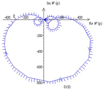
With such a structure of the characteristic equation, the robustness requirement is not violated and need not be corroborated, as a set of limit points of D-decomposition curve for concentrate in point 0. It also follows therefrom that on plane there are no regions , with a possible exception of one point 0. A set of points constructed using Eq. (13) for represent a hodograph determining the structure of D-decomposition of the plane of parameter . When varying from – to + the hodograph becomes a mirror image of the constructed hodograph relative real axis . Keeping in mind the hatching rule, stability region is found. The intersection of the hodograph with the negative real axis will determine maximal cutting depth .
3.6. Results of numerical experiments
Fig. 4 shows D-decomposition along the plane of complex parameter for with the following values of the parameters of the system: boring bar length 3.5 m, external and internal radii of the boring bar 0.04 m, 0.035 m, respectively, cutting velocity 90 m/min; feeding 0.1 mm/rev. Keeping in mind the hatching rule, stability region is found. The intersection of D-decomposition curve with the negative real half-axis determines limiting cutting depth 3.3·10-2m. The second part of D-decomposition curve for is a mirror image of the constructed curve relative the real axis.
Fig. 4D-decomposition along the plane of complex parameter W
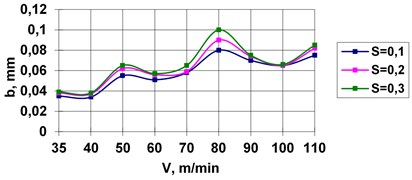
Figs. 5, 6 depict in the plane of parameters , the boundaries of the stability regions for the values of feeding 0.1, 0.2, 0.3 mm/rev, boring bar length 3 m (Fig. 5) and 3.5 m (Fig. 6), boring bar radii 0.04 m, 0.035 m. The stability regions of the equilibrium state are below the boundaries of the stability regions.
It is evident from Figs. 5, 6 that the maximal cutting depth grows with the feeding and cutting velocity (the stability region increases), whereas when the boring bar length increases the maximal cutting depth decreases (the stability region decreases). It is to be noted that the obtained results of numerical studies using the developed mathematical model are in good agreement with the experimental data from [8-16].
Fig. 5Stability regions for various feedings
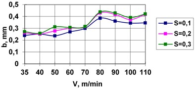
Fig. 6Stability regions for various feedings
4. Conclusions
1) A mathematical model describing coupled torsional and lateral vibrations of a boring bar in deep boring has been developed.
2) A methodology of analyzing stability of the equilibrium state using one complex parameter for a system with lagging is presented.
3) It is found that the stability region increases with the feeding and cutting velocity, and decreases with the increase of the boring bar length.
4) The effect of the parameters of the mathematical model (feeding and cutting velocity, boring bar length) on the value of maximal cutting depth has been analyzed.
5) The results of the numerical-analytical investigation are in good agreement with the experimental ones.
References
-
Utkin N. F., Kizhnyayev Yu I., Pluzhnilov S. K. Deep Boring. Mashinostroyenie, 1988, (in Russian).
-
Kuznetzova Т. I., Маkarov B. G., Nemtzev B. А. On the Damping of Self-Oscillations in Deep Drilling. Collection of Papers on Vibration and Stability of Mechanical Systems. Leningrad State University, 1981, (in Russian).
-
Minkov М. L. Technology of Drilling Deep and High-Precision Orifices. Маshinostroyenie, 1965, (in Russian).
-
Тroitzkiy N. D. Deep drilling. Mashinostroyenie, 1971 (in Russian).
-
Potyagaylo М. V. Drilling Deep and High-Precision Orifices. Маshgiz, 1947, (in Russian).
-
Gorodetskiy Yu I. Constructing Mathematical Models of Complex Self-Oscillatory Systems in Machine Tool Industry. Маshinostroyenie, 1986, p. 203-221, (in Russian).
-
Kudinov V. А. Dynamics of Machine Tools. Маshinostroyenie, 1967, (in Russian).
-
Skuratov D. L., Burmistrovе V., Samykin V. N. Increasing vibration stability of technological systems for machining parts of aircraft engines. Vestnik of Samara State Aerospace University, Vol. 19, Issue 3, 2009, (in Russian).
-
Оrginyan А. А., Balanyukа V. Special characteristics of vibration of console boring bars for fine boring. Information technologies in education, science and production. Materials Technology, Transportology, Vol. 7, Issue 2, 2014, p. 157-168, (in Russian).
-
Standards of Cutting Regimes and Cutter Geometries in Fine Boring. Machining on Fine Boring Machines. Large Scale and Mass Production. Research Institute of Mechanical Engineering, Моscow, 1979, (in Russian).
-
Thil J., Haddag B., Nouar M., Barlier C., Papillon L. Experimental and analytical analyses of the cutting processin the deep hole drilling with BTA (Boring Trepanning Association) system. Mechanics and Industry, Vol. 14, 2013, p. 413-429.
-
How It Works – Getting Bored Today’s Machining World. Boring Machines Remain Vital in Recession-Proof Industries, Vol. 5, Issue 4, 2009.
-
Daghini L. Theoretical and Experimental Study of Tooling Systems. Licentiate Thesis, Royal Institute of Technology, KTH Production Engineering, Stockholm, Sweden, 2008.
-
Zhehe Y., Deqing M. Chatter suppression by parametric excitation: model and experiments. Journal of Sound and Vibration, Vol. 330, Issue 13, 2011, p. 2995-3005.
-
Burdeyna D. М., Horoshilov, Тrishа R. Standardization of the size accuracy of coordinated small-diameter orifices. Control and Navigation Systems, Vol. 40, Issue 4, 2016, p. 138-143.
-
Rezig A., Ouali S. Uppressing boring bar vibrations by parametric excitation. Advances in Рroduction Engineering and Management, Vol. 7, 2012, p. 237-244.
-
Neymark Yu I. Mathematical Modeling as a Science and Art: Manual. 2nd Edition, Nizhniy Novgorod University Publishers, Novgorod, 2010, (in Russian).
Cited by
About this article
The work was financially supported by Russian Scientific Foundation (Grant No. 16-19-10237).
Igumnov L. A. formulation of the problem and supervision of the research. Metrikin V. S. development of numerical and analytical methods of calculations. Lyubimov A. K. development of a mathematical model of a distributed system. Ovchinnikov V. F. development of the method of transition from a distributed mathematical model to a discrete one. Grezina A. V. carrying out and processing of numerical experiments.
