Abstract
A novel knee joint exoskeleton, is designed in this paper, including the mechanical structure and hydraulic damper. To determine the spring parameters of knee joint exoskeleton and verify its effectiveness, we conduct the following studies. Firstly, forward kinematics analysis of the swing phase is obtained and Lagrange dynamics analysis is carried out. Secondly, the 3D model of exoskeleton is set up and ADAMS simulation is conducted. Then the spring parameters of knee joint exoskeleton are selected, including the spring force, the spring stiffness coefficient and the spring expansion, according to the simulation results. Finally, there are three sets of moments on the non-wearable side, the moments resulted from ADAMS simulations, the moments from the CGA (Clinical gait analysis) and the moments calculated from the Lagrange equation are compared, results show they are in good agreement. The effectiveness of the ADAMS simulation proves that the parameters of the hydraulic damper can meet the actual requirements. The simulation analysis of the exoskeleton provides important parameters for the manufacture and it also provides theoretical basis for the later control theory.
1. Introduction
Exoskeleton device, as a wearable device, has been widely used to reduce the energy consumption of human movement in various aspects of the daily life and industry [1, 2]. For example, in the military applications, an exoskeleton is mainly used to improve the soldiers’ fighting capability and the ability to carry weapons. In industrial applications, exoskeleton robots are mainly used to increase the load capacity of the human body in performing maintenances and manufacturing of ships, aircraft and automobile as well as in performing material handling and installation in construction. In addition, the exoskeleton can be used to help a disabled patient with lower limb paralysis, spinal cord injury (SCI) and a gait orthodontic patient to stand up [3]. The exoskeleton can also be used to assist the aged people to walk.
An exoskeleton attached to the leg is used to increase the leg muscle strength and to help those bedridden aged persons and patients with gait disorders to walk again like a normal person [4, 5]. Some lower extremity exoskeletons were also developed to help the paraplegia patients to complete a certain degree of leg movement and some of them were successfully applied to clinical gait corrections [6, 7]. As a result, rehabilitation robots are becoming more and more common [8]. Alterg Bionic Leg is a wearable, battery-powered and robotic mobility assistance device. It can be used as a robotic trainer and can be activated by the patient’s moving intent. The device was used by physical therapists on patients with impaired mobility to strengthen their stance, to improve their gait and to enhance their active motor learning [9, 10]. Alterg Bionic Leg™ can provide patient with the initiation motor assistance during sit-to-stand exercises on ground walking or at stair climbing. Innovative Alterg Bionic Leg allows neuro and orthopedic rehabilitation patients to have more CGA mobility and to complete more repetitions of exercises than previously available legs. It was shown from the clinic or home health therapy [11, 12] that Alterg Bionic Leg™ provided advanced effective robotic assisted rehabilitation therapy to all patients recovering from stroke, orthopedic injury or surgery, incomplete SCI, or traumatic brain injury, as well as to patients with Multiple Sclerosis or general lower extremity weakness. The C-Brace® Orthotronic Mobility System is a computer controlled orthosis and uses an entirely new approach to assist walking for those with back injuries or leg muscle weakness. The intelligent lower limb orthoses can help patients with complete paralysis or partial paralysis by stretching knee muscle tissue. Unlike orthoses, which could only be used to lock or open the knee joint, the latest development C-Brace could be used to provide a real-time intelligent response to the change in user by adjusting the hydraulic resistance in the standing phase and the swing phase [13]. A quasi-passive knee joint exoskeleton was specifically designed to assist running in the Harvard/MIT Division of Health Sciences and Technology and the MIT Media Lab. The device included a linear elastic actuator connected between upper and lower knees. Under the load, the knee joint exoskeleton could be used to assist in stairs climbing and squat. This quasi-passive knee joint exoskeleton device could be used not only to increases the mechanical power of the knee, but also to store and release the energy of the spring-storing energy during lifting leg or heeling off the ground [14-19]. The knee joint exoskeleton has better portability than the lower extremity exoskeleton. Thus, it was more widely used since its light weight could meet patients’ desire to walk [20-22].
Most of the knee joint exoskeletons are driven by a motor, some use spring auxiliary motor to store energy. Compared with motor drive, hydraulic equipment is simple and compact. Thus, a new type of hydraulic damping cylinder design applied in the exoskeleton, the spring in the damper is used as the drive, it absorbs the energy of the walking process and releases it at the right time.
One of the main problems of the knee joint exoskeleton is to select the parameters of the hydraulic damper. Spring as the main part of the damper, it affects the whole equipment. Therefore, we continually adjusted the parameters through the ADAMS simulation analysis until the suitable spring parameters were selected.
2. Structure design
The knee joint exoskeleton is a one degree of freedom. A spring in a hydraulic damper is used to drive the extension of the knee joint. The hydraulic damper has good driving capability and is easy to control while providing smooth driving. The use of hydraulic damper can significantly reduce the quantity of structural components and meet the patients’ requirement-outdoor walking.
2.1. Working principle
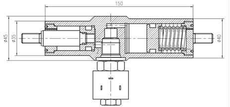
A gait classification based on the order of the walking cycle is shown in Fig. 1, in which the equipped exoskeleton is on patient's right leg. In this classification, the stand phase consists of five phases and the swing period consists of three phases. In the middle of the stance phase (3rd phase in Fig. 1), the right leg is in the upright position and at that moment, the signal is detected by the knee joint angle sensor and the servo valve is closed. When the right heel is off the ground in 4th phase in Fig. 1, the calf is equivalent to a simple pendulum motion and the knee bends in the process of moving. At this moment, the signal is detected by plantar foot pressure sensors and the conduction oil cavity is opened around the servo valve. When it arrives in initial swing phase (6th phase in Fig. 1), right toes are completely off the ground. At that moment, spring compression reaches the maximum, as is shown in the damper state in Fig. 2. When the right leg goes forward, the spring is stretched, which drives the piston to push the piston rod out. In order to control human walking gait in a more natural way, the precise control of the flow rate in the servo value is the key in the process of walking. In other words, the oil mouth size in the servo valve needs to be precisely control in the walking process so that damping can be easily adjusted and ultimately the rate of piston rod extending and retracting is controlled.
Fig. 1The 8 phases of walking

Fig. 2Knee joint exoskeleton hydraulic damper (Unit: mm)
2.2. Model and sizes
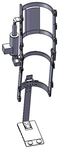
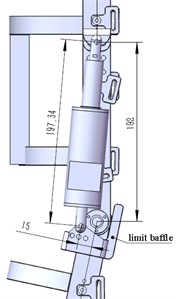
In order to make the light weighted structure, a kind of high strength carbon fiber material is used to connect the lower leg and foot plate, carbon fiber board with adjustable bolt holes, to adapt to the needs of the people with different height. In this study, a one DOF (degree of freedom) knee joint exoskeleton is designed with the target angle of buckling/stretching between 4 and 57°. In addition, a limit baffle is added to impose restraints. A three-dimensional mechanical model of the knee joint is shown in Fig. 3. The hydraulic damper is fixed on the exoskeleton by upper and lower brackets, the upper bracket is connected with the side plate of the upper thigh, and the lower bracket is connected to the calf. The expansion of the knee joint is controlled by the expansion of the damper.
Fig. 3Knee joint exoskeleton mechanical model and sizes (Unit: mm)
a)
b)
3. Kinematics and dynamics analysis
In order to understand the dynamic moment characteristic of human walking, the dynamic modeling method based on the Lagrange equation is presented in this section. Later we will compare them with ADAMS simulation results to verify the simulation results.
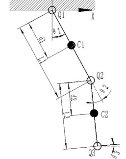
In the process of human walking on the ground, the movement of the knee joint can be divided into a stance phase and a swing phase. In the stance phase, the oil mouth of the hydraulic damper is completely closed to ensure that the body will not fall in this phase. Therefore, the calculation of the knee joint moments in this phase is not needed. In this section, the analysis of kinematics and dynamics are shown only in the swing phase. Since the model of a human walking process can be considered as a symmetry model, only one leg is needed to be analyzed and a simplified model of the knee joint exoskeleton in the swing phase is shown in Fig. 4.
Fig. 4Simplified model of the knee joint exoskeleton. (Q1, Q2, Q3 are joints of hip, knee and ankle. C1, C2 are the center of the thigh and calf)
3.1. Forward kinematics analysis
Ankle joint Q3 is made of a carbon fiber plate. By ignoring the rotational degrees of freedom in the ankle joint, the unilateral lower limb is composed of two link mechanisms and its terminal position can be obtained from the geometric model of the lower limb.
If the human body is fixed, the hip joint can be rotated freely and the center of gravity of the thigh at C1(x1, y1)can be expressed as:
Then, the velocity of the thigh barycenter can be obtained by taking the time derivative of Eq. (1) as:
Similarly, the center of gravity of the calf at C2(x2, y2) can be obtained as follow:
where l1 is the length of the thigh. The velocity of the calf is then derived as:
˙y2=-l1sinθ1˙θ1-d2sin(θ2-θ1)˙θ2+d2sin(θ2-θ1)˙θ1.
3.2. Lagrange dynamic analysis
The system is represented by the Lagrange equation:
where L is the Lagrange operator, which is the difference in kinetic energy EK and potential energy EP: L=EK-EP.
By Eq. (2), the velocity of the thigh can be expressed as:
By Eq. (6), kinetic energy Ek1 and potential energy Ep1 of the thigh then becomes:
The velocity of the knee can be expressed as:
Substitution of Eq. (4), kinetic energy EK2 and potential energy EP2 of the calf can be derived as:
Thus, by Eqs. (7-8) and Eqs. (10-11), the Lagrange operator L becomes:
+m2l1d2˙θ1(˙θ1-˙θ2)cos˙θ2+m1gd1cosθ1+m2gl1cosθ1+m2gd2cos(θ1-θ2),
where I2 is the moment of inertia of the calf. According to the Lagrange dynamic Eq. (5), the hip and knee joint moments of τ1 and τ2 can be obtained as:
+m2gd2sin(θ1-θ2),
-m2gd2sin(θ1-θ2),
where m1 and m2 are the mass of thighs and calves respectively.
4. Adams simulation of knee joint exoskeleton
4.1. Adams model
In this study, SolidWorks was used in the model design of the prototype and ADAMS was used to analyze the designed prototype system. The kinematics and dynamics simulations were carried out using ADAMS. Firstly, 3D models of the human body with SolidWorks was drawn (part sizes are given in Table 1), the knee joint exoskeleton was fitted to the right leg of the human model. After that, an assembly model drawn in SolidWorks was saved as ‘Parasolid’ format, the 3D model was imported into ADAMS. It is important that the state of the human model should be kept in the upright position in SolidWorks before importing it into ADAMS since the 3D model is made of many parts and the adjustment in positions is much complicated and difficult to be carried out in ADAMS.
In ADAMS, each part of body needs to be edited to define the mass attributes, length and the center of mass to ensure the virtual prototype to match the real physical characteristics. Among them, the attributes of the human model were defined including the mass, the center of gravity according to the standard human quality data, and the aluminum alloy was selected as the material for knee joint exoskeleton parts. The upper body of the model was limited to rotation to prevent losing balance during walking. In the meantime, the walking plane was fixed on the earth and contact constraints were also defined between the foot and the platform.
Table 1Normal human body parameters (Male)
The section name of the body | Mass or centroid (Mean value) | Length (Age: 18-55) |
Calf | 2.20 kg | 344 mm |
224.1 mm | ||
Thigh | 8.50 kg | 438 mm |
254.5 mm | ||
Torso | 26.37 kg | 466.8 mm |
Upper arm | 1.46 kg | 284 mm |
Fore arm | 0.75 kg | 213 mm |
The drive function was used to define the walk of the model in ADAMS. The standard data (‘csv’ format) of human gait was shown in Fig. 5, the difference between the left and right legs typed half a cycle. All angular motions were defined based on the CGA data except for the right knee and ankle joints. The unit of the imported data was adjusted as angle and the joint rotation drive was then added. Thus, those joint movements could be defined by the AKISPL function according to the gait parameters. For instance, the hip joint of right leg could be defined as AKISPL (time, 0, Hip, 0). Then spring and damping force (10 N) were added to the hydraulic damper. In addition, the contact condition between the foot and the ground was defined by the contact friction to describe the body walking on the walking plane, the contact friction was defined with 0.5 as the static coefficient of friction and 0.6 as the dynamic coefficient of friction.
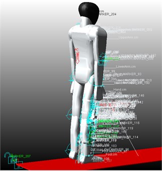
The other conditions imposed in the model including limiting the rotation of the right ankle joint and adding the contact constraint between the limit baffle and exoskeleton. The assembly model is shown in Fig. 6.
Fig. 5Joint angle of human body
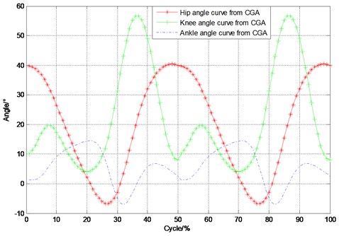
Fig. 6Adams assembly effect
4.2. Spring parameters acquisition
Appropriate spring parameters can be selection through simulations by observing the human walking posture. By constantly modifying the spring parameters in ADAMS, the simulation results are observed, and finally the results are determined. When a spring with its stiffness coefficient at 15 N/mm and a preload at 100 N was used in the simulation, the human walking posture shown in the left side of the Fig. 7 was obtained.
Fig. 7ADAMS simulation results using two different springs with different parameters
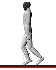
a) Stiffness coefficient: 15 N/mm preload: 100 N
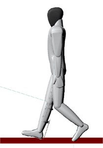
b) Stiffness coefficient: 20 N/mm, preload: 100 N
It clearly shows that the simulation model displays an abnormal walking posture due to an incomplete extension action before the leg landing. When a spring with its stiffness coefficient at 20 N/mm and a preload at 100 N was used, the landing posture of the right leg showed in the right side of the Fig. 7 was obtained. It demonstrates that the use of this spring results in a normal body walking posture, which allows the model to move to the next normal gait. Through the simulation analysis in this study, a spring with its stiffness coefficient at 20 N/mm and a preload at 100 N was preliminarily selected.
Fig. 8Comparison of knee joint angle
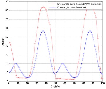
Due to the limit baffle imposed on the knee during the simulation, knee angle should not be less than 4° (normal range is 4-57 degrees according to CGA), which resulted in horizontal line in Fig. 8. The knee angle splines between the CGA and the simulation were compared in Fig. 8. It turns out that the ADAMS simulation curve was on the upper side of the CGA curve, this was reasonable. Since the redundant angle can be adjusted by the hydraulic damper in passive control, so the two curves were suitable.
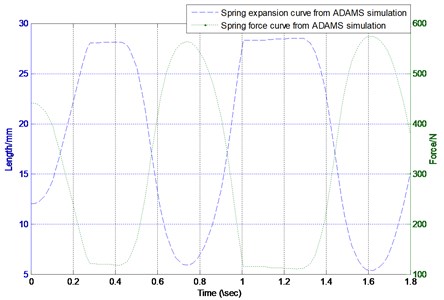
The spring extension and force were also confirmed in the simulation. The simulation results with the simulation time of 1.8 s are shown in Fig. 9. It can be seen from the figure that the maximum spring extension is 23 mm and the force range is between 100 N and 550 N, which is consistent with the spring stiffness coefficient – 20 N/mm.
Fig. 9ADAMS simulation curves
4.3. Simulation results verification
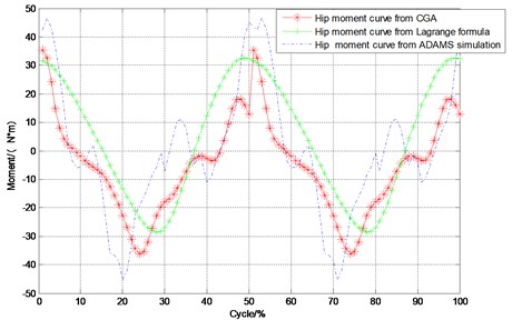
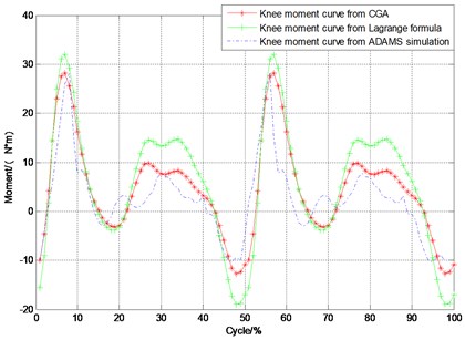
In order to verify the authenticity of the ADAMS simulation results, these three kinds of moment curves, CGA, Lagrange method and ADAMS simulation (left leg), are compared, as shown in Fig. 10. In the calculation of the moments with Lagrange’s equation, Eqs. (13-14) and the data in Table 1 are used.
Fig. 10Hip and knee joint moment curves
a)
b)
In Fig. 10, the moments from the Lagrange calculation and the ADAMS simulation follow a similar trend comparing with the CGA data and it shows a good agreement among them. Using CGA data as the standard, for the hip joint,difference average values of the Lagrange’s method is 11.4213 N·m, ADAMS simulation is 11.3659 N.m. for the knee joint,difference average values of the Lagrange's method is 3.2425 N·m, ADAMS simulation is 4.1925 N·m, these differences are very small. The maximum and minimum moments from the ADAMS simulation agree well with the measurement data, simulation results indicate that selected parameters theoretically have a certain degree of effect.
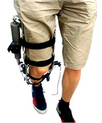
Finally, the knee joint exoskeleton is manufactured with the selected parameters, it can meet a certain degree of comfort as shown in Fig. 11, and before adding control, it has a certain effect.
Fig. 11Wearing test
5. Conclusions
A novel knee joint exoskeleton was introduced in this paper as well as its structure design and working principles. Dynamics analysis was conducted with the Lagrange equation. After verifying the authenticity of the ADAMS simulation, we used computer simulation to select the appropriate parameters of the hydraulic damper, results show that when we select the spring with the stiffness coefficient at 20 N/mm, the preload at 100 N and the resulting hydraulic damping trip was 23 mm thought simulations can be able to meet the requirements.
The control model requires that the error of the dynamic model is less than 15 %, and the average error of the hip and knee moments is within the required accuracy. So, the established dynamic model can meet the requirements.
References
-
Aguirre-Ollinger G., Colgate J. E., Peshkin M. A., Goswami A. Inertia compensation control of a one-degree-of-freedom exoskeleton for lower-limb assistance: initial CGA. IEEE Transactions on Neural Systems and Rehabilitation Engineering, Vol. 20, 2012, p. 68-77.
-
Dollar A., Herr H. Lower extremity exoskeletons and active orthoses: challenges and state of the art. IEEE Transactions on Robotics, Vol. 24, Issue 1, 2008, p. 144-158.
-
Farris Ryan J., Quintero Hugo A., Goldfarb Michael Preliminary evaluation of a powered lower limb orthosis to aid walking in paraplegic individuals. IEEE Transactions on Neural Systems and Rehabilitation Engineering, Vol. 19, 2011, p. 652-659.
-
Erhan A., Mehmet A. A. The design and control of a therapeutic exercise robot for lower limb rehabilitation: physiotherabot. Mechatronics, Vol. 21, Issue 3, 2011, p. 509-522.
-
Lu R., Li Z., Su C. Y., Xue A. Development and learning control of a human limb with a rehabilitation exoskeleton. IEEE Transactions on Industrial Electronics, Vol. 61, 2014, p. 3776-3785.
-
Herr H. Exoskeletons and orthoses: classification, design challenges and future directions. Journal of NeuroEngineering and Rehabilitation, Vol. 6, Issue 21, 2009, https://doi.org/10.1186/1743-0003-6-21.
-
Bogue R. Exoskeletons and robotic prosthetics: a review of recent developments. Industrial Robot: An International Journal, Vol. 36, 2009, p. 421-427.
-
Yin Y. H., Fan Y. J., Xu L. D. Emg and Epp-integrated human-machine interface between the paralyzed and rehabilitation exoskeleton. IEEE Transactions on Information Technology in Biomedicine, Vol. 16, 2012, p. 542-549.
-
The Alterg (Tibion) bionic leg wins the Iera 2013 award. IEEE Robotics and Automation Magazine, Vol. 20, 2013, p. 19-20.
-
Horst R. W. A bio-robotic leg orthosis for rehabilitation and mobility enhancement. Annual International Conference of the IEEE Engineering in Medicine and Biology Society, 2009, p. 5030-5033.
-
Banala S. K., Seok Hun Kim, Agrawal S. K., Scholz J. P. Robot assisted gait training with active leg exoskeleton (ALEX). IEEE Transactions on Neural Systems and Rehabilitation Engineering, Vol. 17, Issue 1, 2009, p. 2-8.
-
Varol H. A., Sup F., Goldfarb M. Real-time gait mode intent recognition of a powered knee and ankle prosthesis for standing and walking. 2nd IEEE RAS and EMBS International Conference On Biomedical Robotics and Biomechatronic, 2008, p. 66-72.
-
Pahl E., Auberger R. Knee ankle foot orthosis with controlled swing and stance phase. Orthopadie-Technik, 2013, p. 28-31.
-
Dollar A. M., Herr H. Design of a quasi-passive knee joint exoskeleton to assist running. IEEE/RSJ International Conference on Intelligent Robots and Systems, Nice, 2008, p. 747-754.
-
Dollar A. M., Herr H. Lower-extremity exoskeletons and active orthoses: challenges and state of the art. IEEE Transactions on Robotics, Vol. 24, Issue 1, 2008, p. 144-158.
-
Horst R. W. A bio-robotic leg orthosis for rehabilitation and mobility enhancement. Annual International Conference of the IEEE Engineering in Medicine and Biology Society, Minneapolis, MN, 2009, p. 5030-5033.
-
Horst R. W., Marcus R. R. Flexcva: a continuously variable actuator for active orthotics. International Conference of the IEEE Engineering in Medicine and Biology Society, New York, NY, 2006, p. 2425-2428.
-
Shamaei K., Napolitano P. C., Dollar A. M. Design and functional evaluation of a quasi-passive compliant stance control knee-ankle-foot orthosis. IEEE Transactions on Neural Systems and Rehabilitation Engineering, Vol. 22, Issue 2, 2014, p. 258-268.
-
Shamaei K., Napolitano P. C., Dollar A. M. A quasi-passive compliant stance control knee-ankle-foot orthosis. IEEE 13th International Conference on Rehabilitation Robotics (ICORR), Seattle, WA, 2013, p. 1-6.
-
Farris R. J., Quintero H. A., Goldfarb M. Preliminary evaluation of a powered lower limb orthosis to aid walking in paraplegic individuals. IEEE Transactions on Neural Systems and Rehabilitation Engineering, Vol. 19, 2011, p. 652-659.
-
Lu R., Li Z., Su C. Y., Xue A. Development and learning control of a human limb with a rehabilitation exoskeleton. IEEE Transactions on Industrial Electronics, Vol. 61, 2014, p. 3776-3785.
-
Wehner M., Quinlivan B., Aubin P. M., Martinez Villalpando E., Baumann M., Stirling L., Holt K., Wood R., Walsh C. A lightweight soft exosuit for gait assistance. IEEE International Conference on Robotics and Automation, 2013, p. 3362-3369.
Cited by
About this article
This study is financially supported by Beijing Higher Education Young Elite Teacher Project (YETP0759) and the Fundamental Research Funds for the Central Universities (No. 2015ZCQ-GX-03).
