Abstract
Clearances in mechanism are inevitable due to the errors from assembly, manufacture and wear. To study the kinetic characteristics of a typical automatic mechanism and the influence of clearances, an experimental device based on a reciprocating mechanism with clearances was set up, and a high speed camera system (HSCS) was used to record the mechanism motions. While the kinetic characteristics were analyzed based on the experimental data from HSCS, a coefficient of initial pressure of gas chamber used to characterize the randomness of the gunpowder gas force was proposed and its distribution was obtained. Meanwhile, the stiffness coefficient and damping coefficient of counterrecoil spring were identified. The virtual prototype model of this automatic mechanism was established. It’s found that the kinetic characteristics from the simulation and the experimental results of stochastic parameters and identification parameters are coincident approximately. Finally, the influence of guide rail’s clearances on kinetic characteristics based on the virtual prototype model was studied.
1. Introduction
Clearances in mechanism are inevitable due to assembly, manufacturing deflection and wear [1]. Moreover, mechanical systems with clearance joints can have a predictable nonlinear dynamic response [2], and the presence of clearance in the joints degrades the performances of the mechanism, leading to high frequency vibration, joint wear [3] and noise [4].
Over the last few decades, dynamic behaviors of mechanisms with clearances have been studied by many researchers. Tian et al. [5] presented a new computational methodology to model and analyze the planar flexible multi-body system with clearance and lubricated revolute joints. The methodology was validated by two numerical examples including a planar flexible double pendulum and a slider-crank mechanism. A slider-crank mechanism with two revolute clearance joints was set up to study the behavior of planar rigid body mechanical systems within the existence of the dynamic interaction of multiple revolute clearance joints [6]. Similarly, the dynamic behaviors of a planar flexible slider-crank mechanism with clearance were studied by Khemili and Romdhane et al. [4] through simulation and experimental tests. Erkaya and Uzmay [7] set up an experimental test rig of a slider-crank mechanism to investigate the effects of joint clearances on vibration and noise characteristics of mechanism. The obtained results show that vibration and noise levels and amplitudes increase with the clearance. Moreover, the dynamic response of a four-bar mechanism having two joints with clearance was investigated by the numerical model with a continuous contact mode and an optimization strategy was proposed to reduce the vibration effect due to the joint clearance [9]. Flores et al. [8] presented a comprehensive combined numerical and investigation on the dynamic response of a slider-crank mechanism with revolute clearance joints. The paper also presented and discussed the correlation between the numerical and experimental results. Chen et al. [10], Lu et al. [11] and Chen [12] presented the dynamic analysis of spur gear pair system with backlash and other parameters based on their nonlinear dynamic model, respectively. Chen et al. [10] studied the effect of backlash on instability of vibration amplitude and dynamic meshing force of the system; Lu et al. [11] discussed the relationship between the dynamic stability of the system and the variance of assembling backlash; Chen and Tang [12] analyzed the effects of different kinds of backlash on nonlinear dynamic response, including constant backlash, time-varying backlash and stochastic backlash. Cui et al. [13] used a numerical integration method to study the dynamic responses of geared rotor systems, including the effect of clearance on jump phenomena of amplitude. Moreover, all the presented results show that the mechanism responses are greatly influenced by the clearance. Thus, it is necessary to study the dynamic behaviors of mechanisms considering clearances in joints.
The automatic mechanism in automatic weapon is a reciprocating motion system with clearances that contains multi-components, and the motion of automatic mechanism has a direct impact on the operation, firing accuracy and safety. Thus, kinetic characteristics analysis is an important procedure in the design process of automatic weapon. The automatic mechanism in AK-47 or a similar structure was applied to other guns in the world due to its reliability, simplicity and durability, e.g. Russian AK-74, Israeli Galil assault rifle, Chinese 81-type and 03-type automatic rifles. To study the kinetic characteristics and the effect of clearances on the motion of this typical automatic mechanism, the experiment and virtual prototype simulation are investigated in this paper.
The paper is organized as follows: Section 2 shows the experimental investigation with a high-speed camera system (HSCS) and the results. Section 3 describes the establishment of the virtual prototype model and comparison with the experimental results. Section 4 is devoted to study the effect of clearances on the motion based on the simulation model. A conclusion ends the paper.
2. Experiment and analysis
2.1. Research object
A diagrammatic graph of an automatic mechanism motion model is shown in Fig. 1. The model includes barrel extension, bolt head, bolt carrier, hammer, counterrecoil spring, receiver and hammer spring. The driving force of the mechanism’s motion is from the gunpowder gas acting on the bolt carrier. The bolt carrier reciprocates along the receiver guide rail by the force from the gunpowder gas and counterrecoil spring. Two typical motions exist:
• Recoil motion: bolt carrier moving from barrel extension to receiver rear end by the gunpowder gas.
• Counterrecoil motion: bolt carrier moving from receiver rear end back to barrel extension during energy release of the counterrecoil spring.
Fig. 1Diagrammatic graph of automatic mechanism
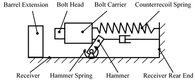
A complete cycle process can be depicted as follows: The recoil motion of bolt carrier begins with a high velocity under the action of gun powder gas, bolt head is pushing to unlock.
Bolt carrier and bolt head move together until colliding with receiver rear end. Meanwhile, the hammer is pressed down by bolt carrier in the recoil motion. Bolt carrier and bolt head carry out counterrecoil motion together under the action of counterrecoil spring force. After bolt head completes the locking action, the counterrecoil motion of bolt carrier would go on until colliding with receiver.
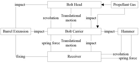
The topological graph of this automatic mechanism is shown in Fig. 2. The bolt carrier is an important research object of this system. Rotational and translational motion both happen between bolt carrier and bolt head when bolt head is unlocking or locking, translational motion also happen between bolt carrier and receiver, and bolt carrier contacts and collides with other components in a whole cycle.
Fig. 2Topological graph of automatic mechanism
2.2. Experimental method
The experimental devices include a high-speed camera system (HSCS), an experiment table and an automatic mechanism. This automatic mechanism was fixed on experiment table, and the motions were recorded by a high-speed camera system (HSCS). In order to obtain the motion of parts in the mechanism, some identification points were marked such as points m1 and m2 on the receiver, points m3 and m4 on the bolt and points m5 and m6 on the counter-recoil spring (shown in Fig. 3). Thus, the motion parameters (displacement, velocity) of every part versus time could be obtained through image recognition on the pictures from HSCS. The experimental device is shown in Fig. 3.
Fig. 3Experimental device

The experimental device may rock slightly as suffering strong impact in the experiment, so data processing is required in order to guarantee the accuracy of experimental data. The Cartesian coordinate system is shown in Fig. 3. The x-axis is horizontal and the y-axis is vertical. For rigid plane motions, it has been validated that if the movements of any two points of a rigid are known, the movement of others can be calculated through coordinate transformation. Therefore, displacements of identification points on receiver (m1 and m2) and identification points on bolt carrier (m3 and m4) were obtained through image recognition. Then, the movement of the point A attached to bolt carrier was calculated through coordinate transformation.
2.3. Stochastic kinetic characteristics analysis of bolt carrier
Fig. 4 shows the experiment displacement curves of the point A attached to bolt carrier during continual firing. It obviously shows that six cyclical peaks appear on the x-displacement curve and each cycle is about 90 ms as well as on the y-displacement curve. It means six firing cycles happen. The maximum x-displacement is about 135 mm, which appears about 30 ms later after beginning. It can be deduced that time cycle of the recoil motion is about 30 ms. The appearance time of a maximum y-displacement is nearly 3 ms later after the maximum x-displacement in each cycle, besides the maximum values are different. It can be concluded that some vibrations appear along the y direction during bolt carrier’s motion due to the existence of clearances through the analysis of Fig. 4. Comparing with the x-displacement, it is found that the maximum y-displacement appears on the beginning of counterrecoil motion, and it is close to the maximum recoil position. By analyzing the structure, a slot designed at the end of receiver guide rail is used to assembly bolt carrier; bolt carrier is unconstrained in y direction as moving to the slot. In addition, bolt carrier gets an upward velocity after colliding with receiver rear end. The maximum y-displacement appears due to the existence of a slot and impact.
Fig. 4Experiment displacement curves of the point A attached to bolt carrier
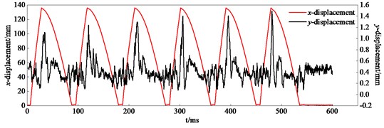
Table 1 presents the statistical results of kinematic parameters of bolt carrier including vmax (maximum recoil velocity), vr (velocity when bolt carrier collides with receiver rear end), vc (velocity when bolt carrier collides with barrel extension), T (cycle of motion) and ymax(maximum y-displacement).
Table 1Statistical results of kinematic parameters of bolt carrier
Items | Mean | Standard deviation | Maximum | Minimum | Range | Shapiro-Wilk significance |
vmax | 8.58 m/s | 0.29 m/s | 9.21 m/s | 8.08 m/s | 1.13 m/s | 0.532 |
vr | 4.88 m/s | 0.23 m/s | 5.31 m/s | 4.30 m/s | 1.01 m/s | 0.222 |
vc | 3.23 m/s | 0.14 m/s | 3.54 m/s | 3.03 m/s | 0.51 m/s | 0.003 |
T | 90.6 ms | 1.64 ms | 93.1 ms | 87.5 ms | 5.6 ms | 0.076 |
ymax | 1.27 mm | 0.18 mm | 1.57 mm | 0.86 mm | 0.72 mm | 0.415 |
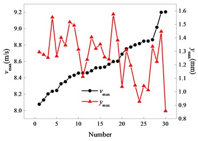
The kinematic parameters’ values of each bolt carrier in Table 1 are dynamic and various. The difference value between maximum and minimum of vmax, vr and vc are 1.13 m/s, 1.01 m/s and 0.51 m/s, and the ratios of the range and the mean are 13.2 %, 20.7 % and 15.8%, respectively. What’s more, the variance range of ymax reaches 56.7 %. It is clear that range’s changes have a strong influence on the stability of automatic mechanism motion, and all kinematic parameters have significant randomness. It is indicated that vmax, vr, T and ymax are approximately normally distributed due to their Shapiro-Wilk Significances are greater than 0.05.
Figs. 5 to 8 present comparisons between vmax and other kinematic parameters of bolt carrier, respectively. Fig. 5 shows that vr generally increases with vmax increasing, but this trend is not obvious in a small range. The correlation between vr and vmax is actually randomness when observing in a small range. There isn’t any obvious trend between vr, T, ymax and vmax in Figs. 6 to 8, it is indicated that there is no obvious correlation between vmax and these kinematic parameters.
3. Simulation and analysis
3.1. Determination on force from gunpowder gas
Bolt carrier recoil is powered by gunpowder gas, which is randomness in actually. Gunpowder gas force is closely related to charge mass, combustion efficiency of gunpowder, environmental factors, etc., and it is difficult to determine the value due to the impact of multiple factors. As the maximum recoil velocity (vmax) represents the recoil energy well, gunpowder gas force is obtained through statistical analysis on the maximum recoil velocities. Table 1 shows that vmax can be considered to have a normal distribution due to Shapiro-Wilk Significance (0.532) which is greater than 0.05. Similarly, it can be also assumed that gunpowder gas force is approximately normally distributed.
Fig. 5Comparison diagram of vmax and vr
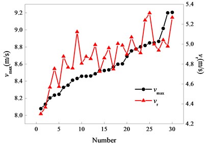
Fig. 6Comparison diagram of vmax and vc
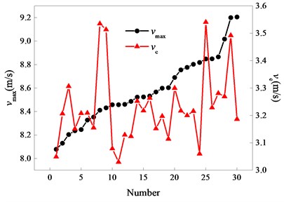
Fig. 7Comparison diagram of vmax and T
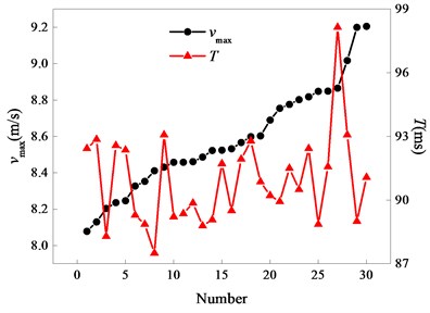
Fig. 8Comparison diagram of vmax and ymax
In order to characterize the randomness of the gunpowder gas force, the coefficient of initial pressure of gas chamber (ξ) is proposed in this paper, which is normally distributed with N(1,0.292) based on the analysis in above (Section 2.3). According to the Brauen empirical formula [14], gunpowder gas force is calculated using the following expression:
where F is gunpowder gas force; A is the area of piston lateral section; pd is in-bore average pressure when bullet arrives at gas port; t is starting time when bullet arrives at gas port; b is a time coefficient related to in-bore pressure impulse; α is a structure coefficient related to structure parameters of gas operated device.
3.2. Counterrecoil spring parameters identification
Stiffness coefficient and damping coefficient of counterrecoil spring have great influence on the performance of automatic mechanism. In order to obtain more accurate parameters, displacements of identification points (m5 and m6, shown in Fig. 3) on the counterrecoil spring were obtained, then the values of stiffness coefficient and damping coefficient were calculated using the least square identification method [15].
Fig. 9Diagrammatic graph of bolt carrier free recoil motion model

Fig. 9 shows the diagrammatic graph of motion model with bolt carrier free recoil, when displacement of bolt carrier is from 90 mm to 135 mm. In this state, the forces acting on bolt carrier in the x direction are counterrecoil spring force (Fx) force and friction (FR). The equation of motion is given by:
where m is the total mass of moving parts; c is the damping coefficient of counterrecoil spring; vi/ai is the velocity/acceleration of bolt carrier at time i. The counterrecoil spring force is written as:
where F1 is the preload of counterrecoil spring; k is the stiffness coefficient of counterrecoil spring; xi is the displacement of bolt carrier at time i.
According to the experimental results, bolt carrier is shaking at this stage, and the contacting time between bolt carrier and receiver guide rail are transient. Thus, friction can be ignored, Eq. (2) transforms into:
where yi=-F1-mai.
According to the least square identification method, Eq. (5) can be derived:
Based on experimental data and Eq. (5), it is concluded that c is 0.00163 N·s/m and k is 229.1 N/m.
3.3. Virtual prototype modeling and validation
The virtual prototype model is established under ADAMS. The model includes 10 rigid bodies, 6 fixed joints, 2 revolute joints, 13 contacts, 2 springs, 1 torsion spring and 12 forces (gunpowder gas force and base pressure in each cycle). The model is shown in Fig. 10.
In this model, gunpowder gas force is calculated by Eq. (1) in Section 2.1, and identification results in Section 2.2 are used to set the parameters of counterrecoil spring. The parametric model of slot related to the receiver guide rail on bolt carrier is used to set different clearances in different cases.
Fig. 11 shows the topological graph of bolt carrier. In order to simulate the real conditions, the joints connecting bolt carrier with bolt head or receiver are replaced by contacts, and the contact force is computed by contact method based on the impact function [4]. The force between ground and bolt carrier is gunpowder gas force; the spring-damper between bolt carrier and counterrecoil spring base fixed on receiver is counterrecoil spring.
Fig. 12 shows the simulation displacement curves of the point A attached to bolt carrier. The model was simulated continuously 6 times. In each cycle, there is a maximum x-displacement and a maximum y-displacement and the maximum y-displacement appears after the maximum x-displacement. The maximum x-displacement is about 135 mm, while the values of maximum y-displacement are different.
Fig. 10Virtual prototype model
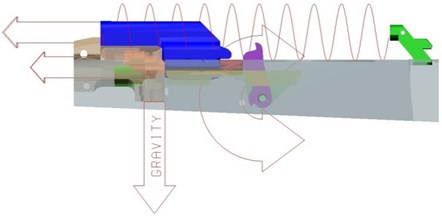
Fig. 11Topological graph of bolt carrier
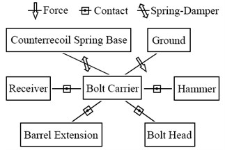
Fig. 12Simulation displacement curves of identification point A on bolt carrier

By comparing Fig. 4 and Fig. 12, it can be concluded that the trends of experiment displacement and simulation displacement are identical. The simulation curves are much smoother than experiment curves due to the experimental device is vibrating while fixed well in simulation model.
Table 2 provides a comparison of statistical simulation results and statistical experiment results on kinematic parameters of bolt carrier. It is clear that the errors of vmax and T are small and less than 5 %; the errors of ymax, vr and vc are larger but less than 14 %, however, both errors are acceptable.
In general, the virtual prototype model considered stochastic gunpowder gas force and identification counterrecoil spring parameters can simulated the motion and the stochastic kinetic characteristics of automatic mechanism well. Thus, it is a good choice to use this simulation model for further analysis of kinetic characteristics.
Table 2Comparison of bolt carrier kinematic parameters
Items | Experiment value | Simulation value | Error |
ymax (mm) | 1.27 | 1.15 | 9.4 % |
vmax (m/s) | 8.58 | 8.27 | 3.6 % |
vr (m/s) | 4.88 | 4.23 | 13.3 % |
vc (m/s) | 3.23 | 3.63 | 12.4 % |
T (ms) | 90.6 | 86.5 | 4.5 % |
4. Influences of guide rail clearance
4.1. Influence of vertical guide rail clearance
The influence of clearance in vertical guide rail (dv, the clearance in y direction) is studied based on the virtual prototype model established in Section 3. The horizontal guide rail clearance (dh, the clearance in z direction) is 0.42 mm; dv is 0.3 mm, 0.5 mm, 0.7 mm, 0.9 mm, 1.1 mm and 1.3 mm, respectively. Simulations with different dv are calculated many times.
The virtual prototype model works well in each case while studying dv effect on the motion. It is concluded that the range of dv in this paper has no significant effects on the function of automatic mechanism.
Fig. 13Simulation y-displacement curves of the point A attached to bolt carrier
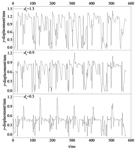
Fig. 13 presents y-displacement curves of point A attached to bolt carrier under different dv. It shows that when dv is small (such as 0.5 mm), there is a maximum y-displacement in each cycle. Meanwhile, the value of maximum y-displacement is also increasing as dv increasing. When dv becomes large (such as 1.3 mm), the characteristic of maximum y-displacement almost disappears.
Figs. 14 to 16 show statistics of bolt carrier related to dv. As shown in Fig. 14, vr generally decreases with dv increasing. On the contrary, the standard deviation of vr increases. It is concluded that the state (i.e. serious collisions, large energy consumption, great randomness) caused by large clearance will happen when bolt carrier does recoil motion with high speed.
Fig. 14Statistics of vr related to dv
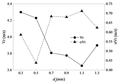
Fig. 15Statistics of vc related to dv
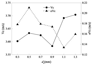
Fig. 16Statistics of T related to dv
As shown in Fig. 15, when dv increases, vc generally increases but the standard deviation of vr decreases due to bolt carrier does counterrecoil motion driven by counterrecoil spring force and the speed increases slowly. By comparing with Fig. 14, the influence of dv on recoil motion is contrary to the influence on counterrecoil motion.
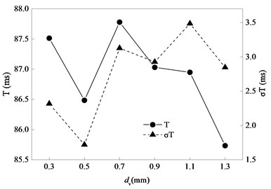
As shown in Fig. 16, there is no obvious correlation between the change of dv and the change of T. However, T is more stable as well as standard deviation of T when dv is small.
4.2. Influence of horizontal guide rail clearance
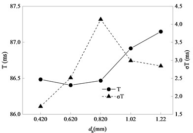
The influence of clearance in horizontal guide rail is studied in this section. The vertical clearance in guide rail is 0.42 mm, dh is 0.42 mm, 0.62 mm, 0.82 mm, 1.02 mm and 1.22 mm, respectively. Simulations with different dh are calculated many times.
The virtual prototype model works well in each case. It is concluded that the ranges of dh in this paper also have no significant effects on the function of automatic mechanism. Fig. 17 presents the statistics of maximum y-displacement of the point A attached to bolt carrier. It shows that if dh is 0.42 mm or 0.62 mm, the maximum y-displacement is about 1mm; if dh is larger than 0.62 mm. the maximum y-displacement decreases by 10.3 %, 15.7 % and 8.9 %, respectively. It is concluded that vibration amplitude in vertical direction will effectively reduce as dh increasing.
Figs. 18 to 20 show statistics of bolt carrier related to dh, respectively. By observing Fig. 18 and Fig. 19, the influence of dh on recoil motion and counterrecoil motion is similar to the influence of dv. Small clearance is of benefit to recoil motion, but large clearance is of benefit to counterrecoil motion. As is shown in Fig. 20, if dh is less than 0.82 mm, T is almost unchanged as dv increasing but the standard deviation of T increases. if dh is larger than 0.82 mm, T increases as dv increasing but the standard deviation of T decreases. In a word, T is small and stable when dv is small.
Fig. 17Statistics of maximum y-displacement of bolt carrier identification point A
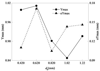
Fig. 18Statistics of vr related to dh
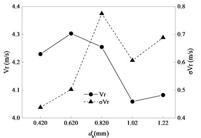
Fig. 19Statistics of vc related to dh
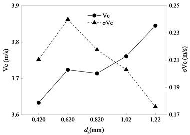
Fig. 20Statistics of T related to dh
5. Conclusions
To study the kinetic characteristics of a typical automatic mechanism with clearances, an experimental device of reciprocating mechanism with clearances was set up; the motions of this experimental device were recorded by a high-speed camera system (HSCS). Based on experimental data, it is found that bolt carrier vibrates in the y direction and there is a maximum y-displacement in each cycle due to the existence of clearances. All kinematic parameters (vmax, vr, vc, T and ymax) have randomness through statistical analysis. It is indicated that vmax, vr, T and ymax are approximately normally distributed due to their Shapiro-Wilk Significances are greater than 0.05. There is no obvious correlation between vmax and other kinematic parameters except vr which generally increases as vmax increasing.
Based on experimental data, a coefficient of initial pressure of gas chamber was proposed and its regularities of distribution was obtained, the stiffness coefficient and damping coefficient of counterrecoil spring were identified. The virtual prototype model of this automatic mechanism was established. The kinetic characteristics of the automatic mechanism were matched well by comparing the simulation results of the virtual prototype model with stochastic parameters and identification parameters from experiments. The virtual prototype model can be used for further analysis of kinetic characteristics.
By analysis of the influence of guide rail clearances on kinetic characteristics, it is concluded that the ranges of dv and dh have no significant effects on the function of automatic mechanism. The influence of guide rail clearances on recoil motion is contrary to the influence on counterrecoil motion, small clearance is of benefit torecoil motion while large clearance is of benefit to counterrecoil motion. There is no obvious correlation between dv and T, the increasing of dh causes the increasing of T. However, T is stable when clearance is small.
References
-
Bai Z. F., Zhao Y. Dynamic behaviour analysis of planar mechanical systems with clearance in revolute joints using a new hybrid contact force model. International Journal of Mechanical Sciences, Vol. 54, Issue 1, 2012, p. 190-205.
-
Flores P. A parametric study on the dynamic response of planar multibody systems with multiple clearance joints. Nonlinear Dynamics, Vol. 61, Issue 61, 2010, p. 633-653.
-
Tian Q., Liu C., Machado M., et al. A new model for dry and lubricated cylindrical joints with clearance in spatial flexible multibody systems. Nonlinear Dynamics, Vol. 64, Issue 1, 2011, p. 25-47.
-
Khemili I., Romdhane L. Dynamic analysis of a flexible slider-crank mechanism with clearance. European Journal of Mechanics Solids, Vol. 27, Issue 5, 2008, p. 882-898.
-
Tian Q., Zhang Y., Chen L., et al. Simulation of planar flexible multibody systems with clearance and lubricated revolute joints. Nonlinear Dynamics, Vol. 60, Issue 4, 2010, p. 489-511.
-
Muvengei O., Kihiu J., Ikua B. Dynamic analysis of planar rigid-body mechanical systems with two-clearance revolute joints. Nonlinear Dynamics, Vol. 73, Issues 1-2, 2013, p. 259-273.
-
Erkaya S., İbrahim Uzmay Experimental investigation of joint clearance effects on the dynamics of a slider-crank mechanism. Multibody System Dynamics, Vol. 24, Issue 1, 2010, p. 81-102.
-
Flores P., Koshy C. S., Lankarani H. M., et al. Numerical and experimental investigation on multibody systems with revolute clearance joints. Nonlinear Dynamics, Vol. 65, Issue 4, 2011, p. 383-398.
-
Erkaya S., İbrahim Uzmay Investigation on effect of joint clearance on dynamics of four-bar mechanism. Nonlinear Dynamics, Vol. 58, Issue 1, 2009, p. 179-198.
-
Chen Huitao, Wu Xiaoling, Qin Datong, Yang Jun Dynamic characteristics of gear transmission system subjected to random internal and external excitation. China Mechanical Engineering, Vol. 24, Issue 4, 2013, p. 533-537.
-
Lu Jianwei, Zeng Fanling, Yang Hansheng, Liu Mengjun Influence of stochastic assembling backlash on nonlinear dynamic behavior of transmission gear pair. Journal of Mechanical Engineering, Vol. 46, Issue 21, 2010, p. 82-86.
-
Chen S. Effect of backlash on dynamics of spur gear pair system with friction and time-varying stiffness. Journal of Mechanical Engineering, Vol. 45, Issue 8, 2009, p. 119-124.
-
Cui Y. Dynamic response of geared rotor system and the effect of clearance on jump characteristics of amplitude. Journal of Mechanical Engineering, Vol. 45, Issue 7, 2009, p. 7-15.
-
Zou Yan, Xu Cheng, Zhang Ke Analysis of kinetic characteristic matching of 5.8 mm/7.62 mm modularized rifles. Acta Armamentarii, Vol. 36, Issue 7, 2015, p. 1356-1362.
-
Wang Shibin, Xu Jia, Zhu Zhongkui LSM-based transient parameter identification and its application in feature extraction of bearing fault. Journal of Mechanical Engineering, Vol. 48, Issue 7, 2012, p. 68-76.
About this article
This project is supported by National Natural Science Foundation of China (Grant No. 51575279).

