Abstract
This paper presents the results of hybrid vibration controllers applied for vibration suppression of flexible manipulator. The model of the manipulator is assumed to be uncertain due to varying payload. To cater for the model uncertainty the proposed hybrid controller combines robust input shaping for command input with μ-controller applied for active vibration suppression using smart materials. Dependence of hybrid controller performance on design frequencies of input shaper is also studied. Results showed that the performance of hybrid controller is strongly dependent on the parameters used for designing input shaper, and the effectiveness of the hybrid controller can be substantially increased by judiciously selecting the design frequencies of input shaper. Effectiveness of the proposed controller is demonstrated by comparative studies with hybrid controllers formed by robust input shaping and PPF (positive position feedback) controller. Results are compared for suppressing vibrations resulting from slewing motion of manipulator, where the slewing motion is controlled by the PD controller. Results of comparisons showed that the μ-controller gave better performance in terms of settling time and energy consumption than those using PPF.
1. Introduction
Space structures ranging from spacecraft itself to robots employed for their servicing and other associated tasks are essentially light weight structures. The light weight of these structures combined with their large size results in low frequency modes which could be excited during the necessary maneuvering of these structures. Since, these structures have to fulfill very stringent performance requirements the vibratory motion of these structures resulting from excitation of low frequency fundamental modes needs to be suppressed as early as possible.
To overcome this problem the early research in this area was focused on input shaping. Initially developed by O. J. M. Smith [1], input shaping is an open-loop technique for vibration suppression that relies on modifying input command by convolving it with a sequence of impulses whose vibrations are self-canceling (see section input shaping). The main advantage of input shaping is its simple design and implementation. Unlike other methods for vibration control which require complex system models, design of input shaper only requires damping and natural frequencies of the modes to be suppressed. Moreover, due to its open-loop nature its implementation doesn’t require any measurement sensor. These advantages have led to vast research in this area which ranges from: (a) improving robustness of input shaper to uncertainty in system natural frequencies; (b) incorporation of auxiliary constraints, such as minimum maneuver time, fuel usage, and transient deflection limits; and (c) implementation on various systems, such as space-based antennas, cranes, flexible manipulators and spacecraft. A comprehensive review on this subject is provided in [2]. However, a major limitation of command shaping, due to absence of feedback loop is that in presence of modeling uncertainties complete elimination of vibrations is not possible.
With the advent of piezoelectric actuators vibration attenuation by using feedback control became particularly attractive for space applications. Fast response, high stiffness, low weight, large operating bandwidth and low power consumption are some of the characteristics which make these actuators suitable for space applications [3]. A number of control techniques have been employed by the researchers for vibration reduction by using feedback control. A comprehensive review of the employed techniques can be found in [4, 5]. However, due to its high vibration attenuation and stability characteristics, PPF is by far the most widely used control technique.
Residual vibrations can be completely eliminated by feedback control, whereas, input shaping can provide considerable reduction in vibration without using extra actuator, sensor and energy. Hence, development of hybrid controllers was a natural outcome. A hybrid controller based on command shaping and PPF was used by [6], results showed the effectiveness of the proposed controller in comparison with either of command shaping and feedback control alone. However, as input shaping and PPF can only guarantee performance for a limited variation in system parameters, the method was not suitable for systems with unknown or largely varying frequencies. To overcome this problem adaptive input shaping is proposed by [7-9]. Instead of adaptive input shaping a hybrid controller with adaptive PPF control and robust input shaping is proposed by [10]. One drawback associated with adaptive techniques either applied for input shaping or feedback control is the real-time computational burden. Moreover, the time required for parameter estimation may result in overall large settling time, because for the multi-mode case and persistent excitation simultaneous parameter estimation and control may possibly lead to erroneous results [11].
Instead of adaptive PPF, a hybrid controller by combining μ-synthesis and robust input shaping is used in this paper. μ-synthesis is an optimal control technique which offers the advantage of maintaining robust performance and stability by incorporating system uncertainties during controller formulation. Other advantages include possible tradeoff among stability, performance, and control energy by using suitable design weights. Also, simultaneous suppression of multiple modes and MIMO controller formulation can be easily achieved through a unified and systematic procedure. The proposed controller is used to suppress vibrations of a flexible manipulator resulting from slewing motion. The slewing motion of the manipulator is controlled by the PD controller. The model of the manipulator is taken as a flexible beam with a variable tip mass (payload). The ranges of system parameters variations are determined by developing manipulator models for a varying payload of 0-1 kg. This payload variation caused an uncertainty of around ±50 % in first modal frequency. Effectiveness of the proposed controller is demonstrated by comparative studies with other hybrid controllers formed by robust input shaping and PPF. Dependence of hybrid controller performance on design frequencies of input shaper is also studied. Results of comparison showed that the hybrid controllers using μ-controller gave better performance in terms of settling time and energy consumption than those using PPF.
The rest of the paper is as follows: mathematical modeling is described in Section 2; principle of input shaping and design of controllers are discussed in Section 3; simulation results are presented in Section 4 and finally Section 5 concludes this paper.
2. Mathematical modeling
The equation governing the dynamic response of a structure embedded with piezoelectric actuators can be expressed using finite element formulation as [12-14]:
where [M], [C], [Kxx], [Kxu] and [Kuu] are the, mass, damping, elastic stiffness, piezoelectric coupling and dielectric stiffness matrices, respectively; X and Fm denote the vectors of structural displacement degrees of freedom (D.O.F) and applied mechanical load respectively; U is the vector of applied piezoelectric actuator voltages; [Km] is a matrix for locations of applied mechanical loads and [Ta] is a matrix of actuator locations with corresponding capacitances.
However, the number of D.O.F, Eq. (1) are usually large and modal transformation is generally applied for obtaining reduced model for control design purposes. The transformation to modal coordinates is expressed as:
where columns of the square matrix [ϕ] are eigenvectors of un-damped homogenous system of Eq. (1) and η represents modal coordinates. By using Eq. (2) and assuming proportional damping, Eq. (1) can be transformed in modal coordinates. The resulting equation can be expressed in abbreviated form as:
By taking the state vector as Ω=[ηT,˙ηT]T and normalizing the eigenvectors in Eq. (2) with respect to mass matrix of Eq. (1), the system model in state space form can be expressed as:
where the system matrices have the following structure:
where C and ω are modal damping and natural frequencies, respectively; B1 and B2 represent input matrices corresponding to applied mechanical loads and piezoelectric actuator inputs; and subscript n, nm, na denote number of modes used in transformation, number of applied mechanical loads and number of piezoelectric actuators inputs, respectively.
Outputs corresponding to sensor measurements can be represented in state space form as follows:
where subscript ny denotes the number of measured outputs; Γ is a matrix of dimension ny×2n, which transforms modal coordinates into physical outputs; matrix D1 with dimension ny×nm is feed through matrix for applied mechanical loads and matrix D2 with dimension ny×na is feed through matrix for applied actuator voltages.
Inputs corresponding to modal disturbances can be included in Eq. (4) as follows [15]:
where the vector of modal forces is represented by ˜f and matrix B3 has the following structure:
The modal response of the system can also be obtained as follows:
With:
Use of commercial finite element software ANSYS for performing closed loop simulations as well as obtaining system model in the form represented by Eqs. (4-5) has been demonstrated by [16-19].
In this paper system model is obtained by performing modal analysis in ANSYS for inputs: (a) input torque for controlling slewing motion, and (b) applied piezoelectric actuator voltage; and outputs corresponding to strains and tip deflection. While the inputs and outputs corresponding to modal disturbances and responses are appended to the system model by using Eqs. (6-7).
The model of the flexible manipulator used in this paper is shown in Fig. 1(a). The manipulator arm is modeled as 2.5 mm thick aluminum beam with material properties: E (Modulus of elasticity) = 69×109 N/m2; ρ (Density) = 2710 kg/m3; υ (Poisson’s ratio) = 0.32. The motor assembly governing the slewing motion is modeled as a rigid hub. The control action for suppressing vibration is provided through, four DuraAct patches (P-876.A15) of ©Physik Instrumente (PI) [20]. A collocated strain gauge is used for providing strain measurements. Manipulator’s dimensions along with locations of actuators and strain gauge are shown in Fig. 1(a). Material properties of piezoelectric patches are provided in Table 1.
Fig. 1Model of manipulator
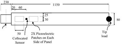
a) Sizes and locations of components

b) Corresponding FEM model of manipulator
Table 1Material properties of piezoelectric actuators
Compliance at constant electric field (m2/N) | Piezoelectric strain matrix (m/V) | Relative permittivity at constant stress | Density (kg/m3) | Free space permittivity (F/m) | |||
S11 | 1.590×10⁻¹¹ | d31 | –1.74×10⁻¹⁰ | ε11 | 1649 | 7800 | 8.85×10⁻¹² |
S33 | 2.097×10⁻¹¹ | d33 | 3.94×10⁻¹⁰ | ε22 | 1649 | ||
S12 | –5.699×10⁻¹² | d15 | 5.35×10⁻¹⁰ | ε33 | 1750 | ||
S13 | –7.376×10⁻¹² | ||||||
S44 | 4.492×10⁻¹¹ | ||||||
S66 | 4.319×10⁻¹¹ | ||||||
The corresponding finite element model of the manipulator is shown in Fig. 1(b). The motor assembly and the tip load are modeled as concentrated masses by using “MASS 21” element. Moment of inertia of the motor assembly about rotation axis is taken as 10 kg/m2. Manipulator’s arm is modeled by using “SOLID 186” element, and “SOLID 226” element is used for piezoelectric patches modeling. The “MASS 21” element (hub) and manipulator arm are connected through constraint equations. A global element size of 12.5 mm is used for meshing. The system model and variations in its parameters are obtained by performing modal analysis for 21 payload values (from 0 to 1 kg with increment of 0.05 kg). The modal analysis is performed by assuming free rotation about axis of rotation and a uniform modal damping ratio of 0.5 %. Detailed procedure for obtaining system matrices through modal analysis is available in [21].
3. Design of controllers and input shaper
The block diagram of the system with proposed hybrid controller configuration is shown in Fig. 2. The inputs, to the plant shown in Fig. 2, correspond to torque applied for slew motion and applied piezoelectric actuator voltage respectively, while the outputs correspond to rotation angle and strains respectively. The inner loop connecting the strain measurements to piezoelectric actuators’ input, via a controller (PPF or μ), provides the means for active vibration suppression. The outer loop, controlled by the PD controller, is responsible for providing the slewing motion. To suppress the vibrations to manageable level, the slew command is applied to the system through an input shaper. The parameters of the input shaper are calculated for a system model with closed outer loop and open inner loop. The control action through piezoelectric actuators is started after the last shaper impulse, this is done to avoid saturation of actuators due to high initial response of the structure. The design details of each component of the configuration shown in Fig. 2 are as follows.
Fig. 2System block diagram for hybrid controller configuration

3.1. PD controller
The slewing motion of the manipulator is controlled by PD controller. The PD controller is designed by using nominal values of system parameters. Proportional and derivative gains of the PD controller used in this paper are taken as 0.185 and 16.8 respectively.
3.2. Input shaping
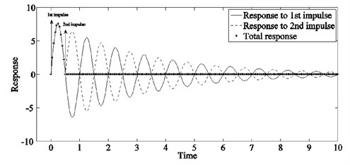
The methodology by which a shaped command moves a flexible system without vibration can be explained by considering the response of an under damped flexible system to impulse inputs. Consider Fig. 3 which for the sake of simplicity shows the response of a single flexible mode to two suitably timed impulses. The total response shows no vibratory motion after the second impulse, this is achieved by cancelling the vibratory motion resulting from 1st impulse by suitably placing the 2nd impulse of appropriate amplitude. A single impulse input can be thought of as a building block of an arbitrary input, hence, properly timed impulse sequence can be used for generating arbitrary vibration reducing inputs. This is achieved by convolving any arbitrary desired input to the system with the impulse sequence called input shaper [2].
Fig. 3Impulse response of a flexible mode for suitably timed impulses
The design of input shaper is achieved by solving the equation governing the system response to an impulse input with a set of constraints. Most types of constraints can be categorized as residual vibration constraints, robustness constraints, impulse amplitude constraints, and the requirement of time optimality. In this paper, a three impulse robust input shaper is used. The formulas for amplitude and time instances of the shaper impulses for suppression of individual mode are [22]:
where K=exp(-(πξ/√1-ξ2)), ξ and ωd are the damping ratio and damped natural frequency of the mode to be suppressed.
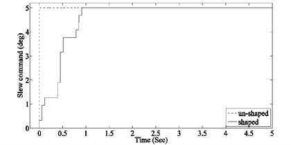
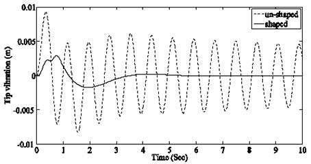
For simultaneous suppression of multiple modes, the final shaper can be composed by convolving the individual shapers [23]. In this paper, the shaper is designed for suppressing first two modes. As discussed earlier the parameters of individual shapers are obtained for a system model with closed outer loop and open inner loop (see Fig. 2). The shaped command designed for the nominal system model (system model developed by taking mean values of system parameter) along with un-shaped input is shown in Fig. 4. The vibratory response of nominal system model at the manipulator’s tip and the response of first two modes, for the shaped and un-shaped inputs are shown in Fig. 5.
Both PPF and input shaping are very effective at their design frequencies, however, both can only guarantee performance for limited variation of system parameters. Hence, for large system parameter variations, the overall effective band of hybrid controller can be increased by placing design frequencies of PPF and input shaper apart. Motivated by this fact the PPF controller in this paper is designed for nominal system parameters while the design frequencies of input shaper are varied in order to constitute the most effective hybrid controller. Hybrid controllers formed by combining these shapers with PPF or μ controllers are discussed in section hybrid controller formulation.
Fig. 4Slew angle command to the system
3.3. PPF controller design
PPF is basically a second order compensator which operates on generalized position output of the structure for generating a force command that is used for suppressing vibration. Due to ease of implementation and high immunity to spillover under collocated actuator/sensor condition, it has been widely used for suppressing vibration of flexible structures [12, 24-36]. Basic structure of the PPF controller when applied for single mode control is shown in Fig. 6.
The design of a PPF controller is based on its three parameters: damping (ξc), frequency (ωc), and gain (K). Guidelines for selecting these parameters have been given in number of studies [24, 32, 35, 36]. In this paper, optimal parameters of the PPF controllers are determined by using analytically derived formulas given by [24].
Fig. 5Nominal system response at manipulator’s tip
a) Total

b) 1st mode

c) 2nd mode
The PPF controller in this paper has been designed for nominal system parameters. The parameters of the designed PPF controllers are given in Table 2.
Table 2Design parameters for PPF controllers
Design parameter | Mode 1 | Mode 2 |
K | 2.5603e+006 | 173.0971 |
ωc | 8.7092 | 55.2087 |
ξc | 0.273 | 0.007 |
Fig. 6PPF control structure
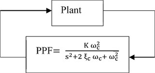
Fig. 7Basic framework for μ-control synthesis
3.4. μ-controller design
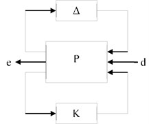
The general framework for the μ-controller design is shown in Fig. 7 Where Δ is norm bounded perturbation which describes the uncertainty structure; P is the open loop interconnection which includes all the scaling and weighting functions used to describe these perturbations, input disturbances, and performance measures; input vector d represents external disturbances to the system; output vector e is used to represent performance measures; and K is the controller. By using linear fractional transformation any linear interconnection of inputs and outputs along with associated uncertainties and controller can be rearranged to match this framework [37].
Detailed system model used for control formulation in this paper is shown in Fig. 8. Since for the considered manipulator model the vibratory response is dominated by the first two modes, a reduced two mode plant model is used for in-bandwidth plant modeling. This reduction of plant model is necessary to keep the order of designed controller reasonable.
Also, to independently control the amount of damping added to each mode, system inputs/outputs corresponding to input torque/tip deflection have been replaced by modal disturbances/modal responses. Independent control of amount of damping is particularly suitable for the type of system considered in this paper, where the amount of damping required for achieving a desired settling time also depends on modal frequency (a mode with higher modal frequency requires less damping for achieving a desired settling time). To keep the actuators effort in reasonable limits a performance output corresponding to controller’s output signal has also been included in the system’s description. The objective is to ensure desired modal damping, in presence of plant uncertainties and control signal limitations, while keeping the system robustly stable. For μ control synthesis this objective has to be represented in terms of infinite norm of the system. Moreover, for meaningful representation of this objective, weights (also shown in Fig. 8) are used for scaling system’s inputs and outputs [38, 39]. The uncertainties considered in this paper for control formulation are due to: (a) variation in system natural frequencies caused by change in payload, and (b) exclusion of higher order system modes from system model. The uncertainty in system matrix due to variation in natural frequencies is modeled as real parametric un-certainty as follows:
where, δi represents the percentage uncertainty in term ω2i (square of the ith modal frequency). Using linear fractional transformation this uncertainty is represented as a 2×2 diagonal block structure ∆st=[δ1δ2] in feedback with the reduced plant model (Fig. 8) [37, 39]. Effect of un-modeled modes is included as complex dynamic uncertainty (Wbound∆ad Fig. 8) [40]. Where Wbound represents the bound on magnitude of un-modeled higher modes and ∆ad is a 1×1complex uncertainty block. Fig. 9 shows 20 random samples of the in-bandwidth model, 20 random samples of the un-modeled system, worst gain of the un-modeled system as a function of frequency and the envelop (Wbound) used for complex dynamic uncertainty.
Fig. 8Modified system block diagram with modified inputs/outputs and associated weights for μ-control synthesis
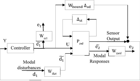
As a general guideline, the weights used for scaling input (Wdist) can be chosen to represent the respective magnitude of exogenous influences as a function of frequency and the weights used for scaling outputs (Wmod, Wact) are chosen as inverse of the bound on desired respective output [38]. Since, a two mode model is used for in-bandwidth modeling, Wdist and Wperf are taken as 2×2 diagonal matrices; where each diagonal entry correspond to the weight selected for the corresponding mode. After performing some trial and error the nominal values of weights selected for controller design are summarized in Table 3.
Table 3Nominal weight values for μ controller
Design parameters/ weights | Nominal values |
Wdist | [0.0581.3817] |
Wmod | [9.71115.56] |
Wact | 0.0045 |
Fig. 9Uncertain system response and bound for residual system
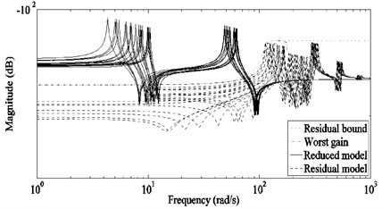
Fig. 10Frequency response of weights used for penalizing system inputs and outputs

a) Modal response weight

b) Modal disturbance weights
The above nominal values of weights have been calculated to provide desired amount of damping for the ith mode at its nominal frequency. For a system with un-certain modal frequencies, the worst response of a mode decreases at 20 dB/decade within its uncertainty band. Hence, for maintaining a constant value of desired closed-loop damping in the uncertainty band, the weight Wmodi (weight for the ith mode) has to be varied accordingly. Fig. 10(a) shows the uncertain modal response Gi (response of the ith mode from ith modal disturbance to ith modal output) along with typical variation of 1/Wmodi that can be used for this purpose. Where, at the ith nominal frequency, the magnitude of frequency dependent Wmodi should be made equal to the nominal Wmodi obtained above.
Also, to limit the band of modal disturbances, variation of Wdisti shown in Fig. 10(b) can be used. Where the magnitude of frequency dependent Wdisti, at the ithnominal frequency, should be made equal to the nominal Wdisti obtained above. In this paper frequency variations, similar to those shown in Fig. 10 have been adopted for 1/Wmodi and Wdisti respectively.
The controller is designed by using mixed μ-synthesis [37-39]. Afterwards, the order of the controller is reduced to 7 by applying “Balanced model truncation via square root method” [38, 41].
3.5. Hybrid controller formulation
The hybrid controllers are formed by combining PPF or μ controllers with input shapers designed for system parameters corresponding to payloads values from 0 to 1 kg with increment of 0.05 kg. The design of input shaper for different values of payloads is done to determine the design parameters of the shaper resulting in most effective hybrid controller. In this paper input shaper designed for system frequencies corresponding to 0.65 kg payload resulted in best hybrid control performance. In order to show the effect of input shaper design frequencies on hybrid controller performance, the results of hybrid controllers with input shapers designed for: (a) nominal system parameters, (b) lowest possible frequencies of each mode, and (c) system parameters corresponding to 0.65 kg payload are presented in next section.
4. Results
A total of eight control configurations have been evaluated in this paper, out of these eight configurations six are hybrid which are formed by combining input shapers with PPF or μ controllers. Details of the parameters used for designing these configurations are summarized in Table 4.
For evaluating the performance of control configurations listed in Table 4, a step command of 5 degree slew angle is given to the manipulator. The performance is evaluated in terms of the settling time required for reducing manipulator’s tip vibration to 1 % of its maximum amplitude in open-loop condition with a 0.5 kg payload. For each control configuration 21 simulations are performed by varying the payload from 0 to 1 kg in steps of 0.05 kg. The required settling time and the power consumed by the active vibration controller (μ or PPF) are recorded for each simulation. The results of the simulations are summarized in terms of four comparative studies as follows.
Table 4Parameters for control configurations
Controller | System parameters used for designing input shaper (IS) | System parameters used for designing controller for vibration suppression |
PPF | – | Nominal system parameters |
μ | – | Uncertainty range of system parameters |
IS nom + PPF | Nominal frequency of each mode | Nominal system parameters |
IS low + PPF | Lowest frequency within uncertainty range of each mode | Nominal system parameters |
IS 0.65kg + PPF | System parameters corresponding to 0.65 kg payload | Nominal system parameters |
IS nom + μ | Nominal frequency of each mode | Uncertainty range of system parameters |
IS low + μ | Lowest frequency within uncertainty range of each mode | Uncertainty range of system parameters |
IS 0.65 kg + μ | System parameters corresponding to 0.65 kg payload | Uncertainty range of system parameters |
4.1. Case A and B
In case A, the results of μ and PPF controller are compared. The resulting settling for the 21 simulations are shown in Fig. 11(a). In case B, the same controllers are combined with the input shaper designed for nominal system frequencies. Simulation results for case B are shown in Fig. 11(b). As can be seen from Fig. 11, although the μ controller configurations performed better than their counterpart PPF configurations the control action for all configurations become ineffective at high payload. One reason for this, is the decrease in system natural frequencies due to increase in payload (motion at high frequency requires less damping for achieving a desired settling time). To overcome this problem the input shaper for case C is designed by using the lowest frequencies within the uncertainty range of each mode.
Fig. 11Settling time required for μ and PPF controllers

a) Without input shaping

b) With input shaping (shaper designed for nominal system frequencies)
4.2. Case C and D
The settling times required for μ, and PPF controllers when combined with input shaper designed using lowest frequencies within the uncertainty range of each mode are shown in Fig. 12(a). The markedly improve results of Fig. 12(a) clearly show the advantage of judiciously choosing the design frequencies of input shaper. Moreover, as in the previous cases the μ controller configurations out-performed their counterpart PPF configurations. To explore the possibility of further improved results the design frequencies of the input shaper are varied, the best results are obtained with input shaper designed for system frequencies corresponding to 0.65 kg payload. These results are shown in Fig. 12(b). Again the μ controller configuration resulted in much better worst settling time as compared with the PPF controller configuration.
Fig. 12Settling time required for μ and PPF controllers

a) With input shaper designed for lowest frequency of each mode

b) With input shaper designed for system parameters corresponding to 0.65 kg payload
Table 5Ratios of power consumed by PPF and μ controllers
Case | Consumed power ratio (μ/PPF) |
Case A: PPF VS μ | 0.67 |
Case B: IS nom + PPF VS IS nom + μ | 0.74 |
Case C: IS low + PPF VS IS low + μ | 0.78 |
Case D: IS 0.65 kg + PPF VS IS 0.65kg + μ | 0.99 |
The ratios of the power consumed by the μ controller to the PPF controllers for all the above cases are given in Table 5. As can be seen in all cases μ controller configurations also resulted in lower power consumption as compared to the respective PPF controller configurations.
4.3. Stability characteristics
The stability characteristics of the whole control system, consisting of both inner (controlled by PD controller) and outer (controlled by PPF or μ controller) loops are determined by assuming simultaneous independent gain and phase variation in each loop. The multi-loop disk gain and phase margin calculated by using balanced sensitivity function [38, 42], for system models corresponding to payload variation of 0-1 kg are shown in Fig. 13. For the considered system models μ controller also resulted in better stability characteristics of the system.
Fig. 13Multi-loop disk margins

a) Gain margin

b) Phase margin
5. Conclusions
Results of hybrid vibration controllers, applied for vibration suppression of an uncertain model of flexible manipulator, are presented in this paper. The proposed hybrid controller combines robust input shaping for command input with μ-controller applied for active vibration suppression using smart materials. Results of comparative studies of the proposed controller with hybrid controllers formed by PPF and input shaping showed, better settling time and power consumption for μ-controllers. Also for the considered system μ controller resulted in better stability characteristics of the system. Moreover, it is shown that that the performance of hybrid controller is strongly dependent on the parameters used for designing input shaper, and the effectiveness of the hybrid controller can be substantially increased by judiciously selecting the design frequencies of input shaper.
References
-
Smith O. J. M. Posicast control of damped oscillatory systems. Proceedings of the IRE, Vol. 45, Issue 9, 1957, p. 1249-1255.
-
Singhose W. Command shaping for flexible systems: a review of the first 50 years. International Journal of Precision Engineering and Manufacturing, Vol. 10, Issue 4, 2009, p. 153-168.
-
Gupta V., Sharma M., Thakur N. Mathematical modeling of actively controlled piezo smart structures: a review. Smart Structures and Systems, Vol. 8, Issue 3, 2011, p. 275-302.
-
Alkhatib R., Golnaraghi M. F. Active structural vibration control: a review. Shock and Vibration Digest, Vol. 35, Issue 5, 2003, p. 367-383.
-
El-Khoury O., Adeli H. Recent advances on vibration control of structures under dynamic loading. Archives of Computational Methods in Engineering, Vol. 20, Issue 4, 2013, p. 353-360.
-
Hu Q., Ma G. Vibration suppression of flexible spacecraft during attitude maneuvers. Journal of Guidance, Control, and Dynamics, Vol. 28, Issue 2, 2005, p. 377-380.
-
Tzes A., Yurkovich S. An adaptive input shaping control scheme for vibration suppression in slewing flexible structures. IEEE Transactions on Control Systems Technology, Vol. 1, Issue 2, 1993, p. 114-121.
-
Bodson M. An adaptive algorithm for the tuning of two input shaping methods. Automatica, Vol. 34, Issue 6, 1998, p. 771-776.
-
Kojima H., Singhose W. Adaptive deflection-limiting control for slewing flexible space structures. Journal of Guidance, Control, and Dynamics, Vol. 30, Issue 1, 2007, p. 61-67.
-
Orszulik R., Shan J. Vibration control using input shaping and adaptive positive position feedback. Journal of Guidance, Control, and Dynamics, Vol. 34, Issue 4, 2011, p. 1031-1044.
-
Goh C. J., Lee T. H. Adaptive modal parameters identification for collocated position feedback vibration control. International Journal of Control, Vol. 53, Issue 3, 1991, p. 597-617.
-
Chang W., Gopinathan S. V., Varadan V. V., Varadan V. K. Design of robust vibration controller for a smart panel using finite element model. ASME Journal of Vibration and Acoustics, Vol. 124, 2002, p. 265-276.
-
Varadan V. V., Gopinathan S. V., Lim Y.-H., Varadan V. K. Radiated noise control via structural vibration control. Proceedings of SPIE Conference on Mathematics and Control in Smart Structures, Vol. 3323, 1998, p. 546-553.
-
Lim Y.-H., Varadan V. V., Varadan V. K. Closed loop finite element modeling of active structural damping in the frequency domain. Smart Materials and Structures, Vol. 8, 1997, p. 161-168.
-
Iorga L., Baruh H., Ursu I. H∞ control with µ-analysis of a piezoelectric actuated plate. Journal of Vibration and Control, Vol. 15, Issue 8, 2009, p. 1143-1171.
-
Khot S., Yelve N. P., Tomar R., Desai S., Vittal S. Active vibration control of cantilever beam by using PID based output feedback controller. Journal of Vibration and Control, Vol. 18, Issue 3, 2012, p. 366-372.
-
Meng G., Ye L., Dong X., Wei K. Closed loop finite element modeling of piezoelectric smart structures. Shock and Vibration, Vol. 13, Issue 1, 2006, p. 1-12.
-
Dong X., Peng Z., Zhang W., Hua H., Meng G. Research on spillover effects for vibration control of piezoelectric smart structures by ANSYS. Mathematical Problems in Engineering, Vol. 2014, 2014, p. 1–8.
-
Malgaca L., Karagülle H. Numerical and experimental study on integration of control actions into the finite element solutions in smart structures. Shock and Vibration, Vol. 16, Issue 4, 2009, p. 401-415.
-
Instrumente P. PI Datasheet P-876. 2016, http://www.piceramic.com/product-detail-page/p-876-101790.html.
-
ANSYS 14.5 Help. 2012.
-
Singer N. C., Seering W. P. Preshaping command inputs to reduce system vibration. Journal of Dynamic Systems, Measurement, and Control, Vol. 112, Issue 1, 1990, p. 76-82.
-
Singer N. C. Residual Vibration Reduction in Computer Controlled Machines. Report AITR-1030, 1989.
-
Starek L., Fenik S. Optimal ppf controller for multimodal vibration suppression. Engineering Mechanics, Vol. 15, Issue 3, 2008, p. 153-173.
-
Goh C. J., Caughey T. K. On the stability problem caused by finite actuator dynamics in the collocated control of large space structures. International Journal of Control, Vol. 41, Issue 3, 1985, p. 787-802.
-
Song G., Agrawal B. N. Vibration suppression of flexible spacecraft during attitude control. Acta Astronautica, Vol. 49, Issue 2, 2001, p. 73-83.
-
Shan J., Liu H. T., Sun D. Slewing and vibration control of a single-link flexible manipulator by positive position feedback (PPF). Mechatronics, Vol. 15, Issue 4, 2005, p. 487-503.
-
Hu Q., Ma G. Spacecraft vibration suppression using variable structure output feedback control and smart materials. Journal of Vibration and Acoustics, Vol. 128, Issue 2, 2006, p. 221-230.
-
Mahmoodi S. N., Aagaah M. R., Ahmadian M. Active vibration control of aerospace structures using a modified positive position feedback method. American Control Conference, 2009, p. 4115-4120.
-
Jiang Y., Hu Q., Ma G. Attitude maneuvering and vibration reducing control of flexible spacecraft using smart materials. Proceedings of the Institution of Mechanical Engineers, Part G: Journal of Aerospace Engineering, Vol. 222, Issue 3, 2008, p. 357-367.
-
Orszulik R., Shan J. J. Multi-mode adaptive positive position feedback: an experimental study. American Control Conference, 2011, p. 3315-3319.
-
Orszulik R. R., Shan J. Active vibration control using genetic algorithm-based system identification and positive position feedback. Smart Materials and Structures, Vol. 21, Issue 5, 2012, p. 055002.
-
Ferrari G., Amabili M. Active vibration control of a sandwich plate by non-collocated positive position feedback. Journal of Sound and Vibration, Vol. 342, 2015, p. 44-56.
-
Caughey T. K., Fanson J. L. Positive position feedback control for large space structures. AIAA Journal, Vol. 28, Issue 4, 1990, p. 717-724.
-
Friswell M. I., Inman D. J. The relationship between positive position feedback and output feedback controllers. Smart Materials and Structures, Vol. 8, Issue 3, 1999, p. 285-291.
-
Song G. S. G., Schmidt S. P., Agrawal B. N. Experimental study of active vibration suppression of flexible structure using modular control patch. IEEE Aerospace Conference Proceedings (Cat. No. 98TH8339), Vol. 1, 1998, p. 189-201.
-
Zhou K., Doyle J. C. Essentials of Robust Control. First Edition, Prentice-Hall, New Jersey, 1998.
-
Matlab 2014(a) Help. MathWorks, 2014.
-
Balas G. J., Doyle J. C., Glover K., Packard A., Smith R. µ-Analysis and Synthesis Toolbox for use with MATLAB. The MathWorks, Inc., Natick, MA. 2001.
-
Balas G. J., Doyle J. C. Control of lightly damped, flexible modes in the controller crossover region. Journal of Guidance, Control, and Dynamics, Vol. 17, Issue 2, 1994, p. 370-377.
-
Safonov M. G., Chiang R. Y. A Schur method for balanced-truncation model reduction. IEEE Transactions on Automatic Control, Vol. 34, Issue 7, 1989, p. 729-733.
-
Blight J. D., Lane Dailey R., Gangsaas D. Practical control law design for aircraft using multivariable techniques. International Journal of Control, Vol. 59, Issue 1, 1994, p. 93-137.

