Abstract
Among the other noise problems, the low-frequency booming noise is the most annoying one. The booming noise significantly reduces the total quality perception of the brand. In this study, the contributions of secondary components to the booming noise are investigated. The general aspects of the problem are given for the sake of completeness. The causes of low-frequency booming noise are explained. The widely accepted procedure for the booming noise is discussed through the results of a case study, where an automobile equipped with a diesel engine is studied. In the case study, two different secondary components that cause booming noise are identified experimentally. It is proposed to improve the widely accepted procedure by adding an extra step for the secondary components. In some cases, the secondary components are the main causes of the unforeseen noise and vibration problems, as the current study reveals.
1. Introduction
For a large section of automobile customers, interior noise quality may be not an important decision factor as much as styling, power, fuel consumption and budget, while choosing an automobile to buy. But in the long term, noise, vibration and harshness (NVH) quality significantly influences the customer satisfaction, which in turn shapes the brand image of the vehicle manufacturer. Although there is a huge research on this topic, noise and vibration problems are still take up most of the time of the customer pleasant departments of the vehicle manufacturers [1].
Automobiles are very complex structures in terms of engineering. It can be said that before the serial production, every new model is a big optimization problem, which has to be solved by many different disciplines of engineering. The possible solutions of NVH problems often conflict with the other design criterions, such as total mass, handling behavior and other dynamic calculations. These conflicts restrict the options and force the NVH engineers to come up with palliative or barely solutions. Minor modifications done after the serial production is another difficulty. These modifications may cancel the effects of the countermeasures developed.
While designing a new automobile, the virtual prototype (i.e. computational model) is developed before the physical one. At this step, an initial NVH analysis is often performed using the deterministic element-based computational software tools, such as finite element (FE) and/or boundary element (BE) methods. In the low-frequency range, the structure borne noise is dominant due to the masking effects of sound [2]. The computational model of the unibody (a.k.a. body-in white) is used to evaluate the structure borne sound occurred in the full vehicle. To examine the probable low-frequency problems, the structure borne sound is simulated through a coupled vibro-acoustic analysis, which counts on the structure-fluid interaction, as well [3]. Then, the physical prototype is subjected to experimental studies to verify and complement the computational unibody model.
The next step somehow increases the complexity of the procedure: many new components are added to the unibody, and the major one is the powertrain. Actually, the low-frequency noise problems are powertrain induced [4]. The powertrain is attached to the unibody through the engine and exhaust mounts. The mounts make it possible to filter and tune the vibrations spreading over the unibody. Even all of these steps are managed successfully; some other auxiliary components may still cause serious noise and vibration problems.
The powertrain and the unibody are the active and the passive parts of the system, respectively. The unibody is the primary component that introduces vibration energy into the air cavity of the automobile. The structure-fluid interaction between the unibody and the confined air in the cavity designates the acoustic characteristics of the vibro-acoustic system. The secondary components like the front cradle, the axles and the bumpers are also the parts of the vibro-acoustic system. Although these components do not have a direct interaction with the powertrain, vibration energy enters to these secondary components through the unibody. The response of secondary components may have critical effects on the dynamic characteristics of the structure, if they are excited in their eigenfrequencies [1]. The current study investigates the effects of secondary components on the interior noise and vibration characteristics of automobiles.
2. General aspects of the problem
In the context of vehicle acoustics, noise and vibration studies are commonly classified in different frequency regimes, such as low-(20-200 Hz), mid-(200-600 Hz) and high-frequency (600 Hz and beyond) bands and handled using different methods like experimental, computational and hybrid considerations. Up to date, there is no single best solution procedure, which spans the whole frequency band. Instead, the mentioned frequency regimes are studied using different methods due to the distribution of modal density, which is a function of frequency. Since modal density is low, deterministic element-based methods are appropriate for the low-frequency range to come up with a solution. For the high-frequency range, where the modal density is high, statistical methods are useful. For the low-mid and the mid-high frequency bands, hybrid computational methods, which utilize from both of the deterministic and statistical procedures, are widely employed to overcome mid-frequency modeling troubles.
In the low-frequency range, namely below 200 Hz, the structure borne sound is dominant. The structure borne sound is caused by the displacements of the body panels and the frame that construct the unibody. The unibody can be described as the metallic structure of an automobile (see Fig. 1). It has no doors, no trim parts, but has a windscreen and a rear glass to consider the effect of dominant longitudinal acoustic modes. In the low-frequency range, the main source of vibration is the powertrain [1].
Fig. 1The virtual prototype of the studied automobile
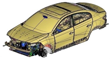
a) The full vehicle
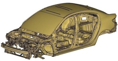
b) The unibody
To validate the computational unibody model, experimental models are constructed. Experimental modal analysis (EMA) technique is often used to compute the structural modes of the unibody. Experimentally validated computational model can then be used for vibration and noise refinement procedures. The widely accepted procedure for the low-frequency NVH analysis, which is implemented after the construction of the physical prototype, can be outlined as follows:
1) Perform a track test according to the standards [5]. Measure the operational vibration and/or noise in the target locations.
2) Construct an FE model of the unibody (structural analysis).
3) Construct an FE or a BE model of the acoustic cavity (acoustical analysis).
4) Design an EMA study to compute the structural modes and the damping characteristics.
5) Synthesize the outcomes of the experimental and computational models to construct a coupled vibro-acoustic analysis.
6) Identify the dynamic powertrain forces transmitted to the structure.
7) Simulate the final verified model through a forced vibration analysis.
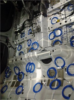
Notice that, the problem with the outlined procedure is that the secondary components are ignored. It can be said that one can readily apply the above procedure to a full vehicle in order to consider the secondary components, as well. However, the procedure is not so straightforward, not only in terms of the computational cost, but also in the way of the experimental techniques. Namely, the unibody is already a very complex structure as a result of mass, topography and topology optimization studies. For a robust computation, at least 3 million degrees of freedom is required. The computational cost of a full vehicle simulation will be huge. Even, such a deterministic simulation is performed; it will not be so reliable, because of the manufacturing variability. Furthermore, the experimental verification of such a model is hard, if not impossible. For the experimentation, the metallic part of the body should be fully accessible to locate the sensors. The panels of the vehicle are covered with the trim parts. To measure the frequency response functions (FRFs), all of the trim parts can be removed as shown in Fig. 2. (The photograph shown in Fig. 2 is taken during a previous study, which examines the acceleration responses of body panels to a random input.) Beside the accessibility problems, the nonlinearity introduced by the elastomeric parts and the bushings significantly reduces the ordinary coherence values, which are important in examining the accuracy of the experimentation. Thus, it is reasonable to carry an experimentation campaign starting with the unibody in its simplest and plain form. Once getting accurate results, where the assessment is made in terms of coherence values [3], the plain unibody model may then be improved step by step by adding the secondary components.
Hence, the current study offers to add one more step to the outlined procedure, provided that the results of the track test and the final computational model do not match well. This step requires making additional tests on the full vehicle to improve the final simulation model mentioned in the last step of the procedure (item 7). The outlined procedure is studied on an automobile equipped with a four-cylindered diesel engine.
Fig. 2In a previous study, the trim parts of the automobile are removed to access the floor panel
3. Application of the procedure
1) First, sound pressure levels (SPLs) are measured at the target locations, during the track test, which is performed according to the standards [5]. The accelerations at the active and the passive sides of the powertrain are measured, as well. The latter measurements are used later on to identify the operational forces acting on the unibody (see Eq. (1)). Data are acquired using LMS Scadas SCM09 mobile analyzer, PCB three axis accelerometers and PCB 12 mm microphones.
2) Using the computer-aided drawing (CAD) of the automobile, an FE model of the unibody is constructed through Altair/Hypermesh™ package. The properties of the model are tabulated in Table 1. To render a computational modal analysis possible, the FE model is assembled through rigid connections, bolts, glue, spot and seam welds.
3) An FE model of the acoustic cavity is constructed using HEXA8 type elements. Through LMS Virtual Lab™ software, eigenfrequencies are extracted, where both of the Lanczos and Arnoldi algorithms are used to enable a double check. Number of elements per wave length is defined as six, whereas the speed of sound and the density of air are taken as 340 m/s and 1.220 kg/m3, respectively. The FE models of the structure and the acoustic cavity are shown in Fig. 4.
Fig. 3The mobile analyzer used during the track test
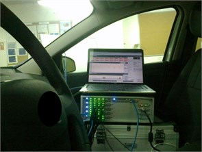
Fig. 4The FE model of the structure and the acoustic cavity
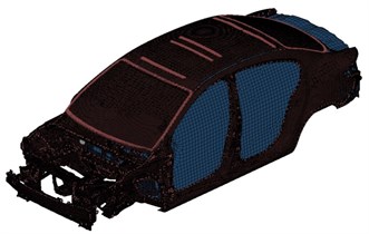
Fig. 5Local axes are attached on every node of the wireframe
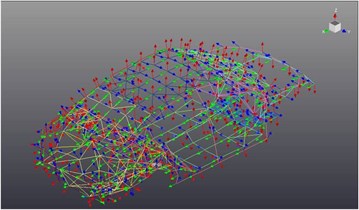
Table 1Element types and quantities used in the finite element model of the automobile
Element type | QUAD4 | TRIA3 | HEXA8 | TET10 | Spider | Interpolation | Beam |
Quantity | 1,231,152 | 62,390 | 1,655 | 11,787 | 777 | 11,281 | 10 |
Table 2Experimental modal analysis results: damped natural frequencies (ωd) in Hz and the corresponding percent damping (ζ) values
Mode | ωd | ζ | Mode | ωd | ζ | Mode | ωd | ζ |
1 | 33.65 | 1.61 | 15 | 94.45 | 1.12 | 29 | 152.81 | 1.04 |
2 | 42.16 | 0.78 | 16 | 96.22 | 0.68 | 30 | 154..63 | 0.92 |
3 | 47.53 | 2.83 | 17 | 104.25 | 1.36 | 31 | 157.14 | 1.28 |
4 | 51.19 | 0.96 | 18 | 109,83 | 1.65 | 32 | 161.67 | 0.76 |
5 | 53.62 | 1.29 | 19 | 111.92 | 0.96 | 33 | 165.30 | 1.38 |
6 | 57.79 | 0.48 | 20 | 113.86 | 1.27 | 34 | 167.36 | 0.97 |
7 | 61.12 | 0.89 | 21 | 115.61 | 1.36 | 35 | 168.78 | 0.61 |
8 | 64.56 | 0.72 | 22 | 119,67 | 0.77 | 36 | 171.89 | 1.27 |
9 | 71.80 | 1.14 | 23 | 121.46 | 0.56 | 37 | 174.51 | 0.58 |
10 | 74.38 | 1.08 | 24 | 124.11 | 1.03 | 38 | 179.37 | 1.11 |
11 | 76.55 | 1.23 | 25 | 127.73 | 0.47 | 39 | 183.45 | 1.59 |
12 | 79.61 | 0.74 | 26 | 133,55 | 1.07 | 40 | 189.14 | 1.45 |
13 | 83.24 | 1.49 | 27 | 138.26 | 1.18 | 41 | 193.91 | 1.67 |
14 | 91.56 | 1.06 | 28 | 143.77 | 1.34 | 42 | 195.75 | 1.44 |
4) Although the general frame of the analysis is well-known, every EMA study is somehow tailored in terms of the sensor locations and the parameters selected (see e.g. Ref. [3] for a detailed study). A wireframe (i.e. a reduced computational model) is constructed using the computational unibody model. The constructed wireframe has all the information, which is assigned to the computational unibody model. Several test parameters are determined for the EMA study [3]. The structure is excited simultaneously in y- and z-directions using the Modal Shop™ K2100B modal shaker kits. The test data are acquired through the uniaxial accelerometers located normal to the plane. Differently, elements of the FE model take the global axis as a reference. Before any correlation study, the wireframe has to be geometrically aligned, such that the nodes of the model must be compatible with the test data. This is achieved by assigning local axes to all nodes of the wireframe, which correspond to the output locations of the test model. In Fig. 5, the local axes attached to the nodes are shown. In total, there are 240 nodes on the wireframe shown.
5) Next to the acquisition of the data, complex mode indicator function (CMIF) [6] is employed to investigate the existence of normal, and/or complex modes. Peaks determined by the CMIF indicate the corresponding eigenfrequencies of associated modes. CMIF calculations are made using a MATLAB™ script. Damped natural frequencies and the damping ratios are calculated and tabulated in Table 2. The calculated damping values are then imposed on the undamped computational model to enable a robust vibro-acoustic simulation. Hence, the results of the experimental analysis and the outcomes of the computational studies are used to validate and complement each other. The correlation is conducted through the well-known modal assurance criterion (MAC) [7].
6) To perform a forced vibration simulation, the dynamic forces exerted on the structure have to be known. The dynamic forces are identified using the matrix inversion technique, i.e:
where fiis the dynamic force that applied through the pathi; ¨Yi/Fj is the accelerance type FRF and ¨yi is the operational body side acceleration. The operational body side acceleration vector is measured during the track test (Step 1). Vibration is transmitted to the structure through 5 mounts (3 engine mounts and 2 exhaust mounts). For the transmission of vibration, only the translational directions are considered. Hence, the number of paths is determined as 15 in Eq. (1).
7) The full computational model is simulated through a coupled vibro-acoustic analysis, where structure-fluid interaction is considered, as well. The output of the analysis is the sound pressure level predicted at the driver’s left ear location. The coupled vibro-acoustic problem is expressed by:
where M, C, K denote mass, damping and stiffness matrices; w is the nodal displacement vector of the structure at the boundary; p is the sound pressure vector of the interior sound field; F is the structural and/or the acoustical load vector; the indices s, a and c stand for structure, acoustic and coupled, respectively. Herein, the term ‘coupled’ refers to the coupling of acoustic and structural domains. The coupling is achieved by equating the mobilities of the acoustic and the structural domains at the boundary.
4. The effects of secondary components
In the employed procedure, it is assumed that the acoustic spectra are shaped by the pressure fluctuations occurred in the confined air, which is surrounded by the vibrating body panels. The low-frequency booming noise can be described as the resonance behavior of the air cavity. This mechanism occurs, when the acoustic modes are excited in their eigenfrequencies by the vibrating cabin walls. Yet another assumption is that the unibody of the automobile is capable in representing the structural part of the vibro-acoustic analysis, at least in the low-frequency region. These assumptions are validated and reported numerous times ever since the study of Jha, which is going back to 70 s [8] (see also Ref. [9] for a detailed review of the literature). Note that, the definition of the unibody is not unique in terms of computational modelling, although the one described in the current study is widely accepted [10].
Fig. 6The insitu testing of the secondary components
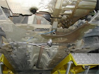
a) The front cradle
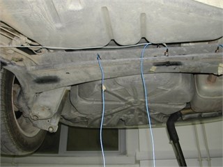
b) The rear axle
Fig. 7The eigenfrequency of the torsion bar is measured as 125 Hz
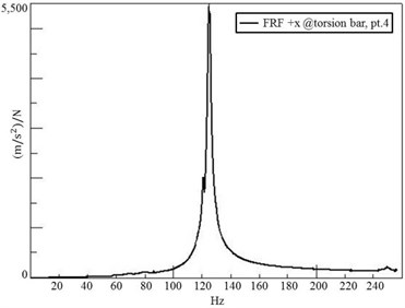
Next to the application of the described procedure, additional tests are performed on the full vehicle and its unibody, as well. The secondary components, which are subjected to the insitu testing, are the following: the front cradle, the axles and the bumpers. For the insitu testing, three axis accelerometers and an instrumented impact hammer with an appropriate tip are used (see Fig. 6). In the full vehicle test, the noise transfer functions between the secondary components and the target microphone locations are measured. The raw data of acceleration of the components are processed. The structural eigenfrequencies of the components are identified (see Fig. 7). It is observed that the torsion bar located in the rear axle has an eigenfrequency value of 125 Hz and the front cradle has an eigenfrequency value of 137 Hz. It is found that these two secondary components make significant contributions to the booming noise.
The identified booming noise takes up a wide region in the dB-rpm curve as shown in Fig. 8. The specification curve shown in Fig. 8 is determined by the OEM, based on their expectations. It is shaped by the customer feedbacks and the acoustic characteristics of the competitor vehicles. According to the specification curve, the booming noise is occurred in the 3.500 rpm-4.200 rpm interval (or 116.6 Hz-140.0 Hz), which covers the area of cruise speed. This annoying noise is mostly contributed by the torsion bar and the front cradle in the studied automobile. The studied automobile is equipped with a four-cylindered diesel engine. Note that, the curves shown here are derived from the second order data, which is dominant for the four-cylindered engines. The second order can be defined as the second harmonic of the rotational frequency of the crankshaft.
Fig. 8The specification curve and the sound pressure levels measured during the track test
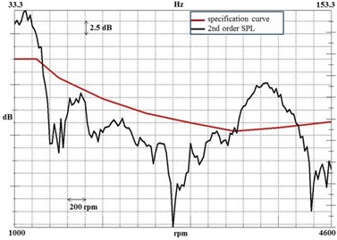
Fig. 9The comparison of measured and predicted sound pressure levels
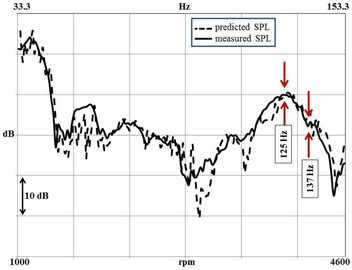
According to the outcomes of the insitu testing, computational unibody modeling step of the procedure (i.e. step 2) is revisited to improve the model. The secondary components, which are identified as the significant contributors of the booming noise are added to the FE model. Next, a coupled vibro-acoustic simulation is performed using the improved FE model. A robust model that enables accurate predictions is achieved. The measured and the predicted sound pressure levels are compared in Fig. 9.
5. Conclusions
In the automobile development process, to find out the root causes of low-frequency booming noise is critical. The widely-accepted procedure for the booming noise is discussed. The steps of the procedure are explained in detail and a case study is given. To achieve more accurate results, it is proposed to add an extra step to the procedure. Following conclusions are made:
1) Experimental analysis is indispensable for measuring the damping characteristics, and the computational analysis is a requirement for modeling the acoustic-structure coupling. Hence, the computational and experimental steps of the procedure complement each other.
2) It is reasonable to use the unibody in its simplest form for the computational modelling due to the computational cost and the physical obstacles faced during the experimentation.
3) Experimental studies must be performed on both the full vehicle and its unibody. The full vehicle test is required to measure the NTFs between the secondary components and the target microphone locations.
4) The proposed procedure reveals the effects of secondary components on the booming noise, if any.
5) The torsion bar and the front cradle have the eigenfrequency values of 125 Hz and 137 Hz, respectively. For the given case, it is observed that these two secondary components are the main contributors of the booming noise diagnosed.
References
-
Sheng G. Vehicle Noise, Vibration, and Sound Quality. Warrendale, SAE International, 2012.
-
Dunn F., Hartmann W. M., Campbell D. M., Fletcher N. H. Springer Handbook of Acoustics. Springer, 2015.
-
Oktav A. Experimental and numerical modal analysis of a passenger vehicle. International Journal of Vehicle Noise and Vibration, Vol. 12, Issue 4, 2016, p. 302-313.
-
Novotny P., Prokop A., Zubík M., Řehák K. Investigating the influence of computational model complexity on noise and vibration modeling of powertrain. Journal of Vibroengineering, Vol. 18, Issue 1, 2016, p. 378-393.
-
Acoustics Measurement of Noise Inside Motor Vehicles. The International Organization for Standardization, ISO 5128, 1980.
-
Reynders E. System identification methods for (operational) modal analysis: review and comparison. Archives of Computational Methods in Engineering, Vol. 19, Issue 1, 2012, p. 51-124.
-
Allemang R. J. The modal assurance criterion-twenty years of use and abuse. Sound and Vibration, Vol. 37, Issue 8, 2003, p. 14-23.
-
Jha S. K., Priede T. Origin of low frequency noise in motor cars. 14th Automobile Technologies Congress of FISITA, London, 1972.
-
Lalor N., Priebsch H. H. The prediction of low- and mid-frequency internal road vehicle noise: a literature survey. Proceedings of the Institution of Mechanical Engineers, Part D: Journal of Automobile Engineering, Vol. 221, Issue 3, 2007, p. 245-269.
-
Priebsch H. H., Hauer I., Fellner H., Polt G., Brandl F. Numerical simulation of vehicle interior noise up to 250 Hz. Integrated Vehicle Acoustics and Comfort, Styrian Noise, Vibration and Harshness Congress, Graz, 2001.
