Abstract
An experiment of the effect of internal flow velocity on vortex induced vibration characteristics of vertical top tension risers was carried out in a large scale wind-wave-current flume. A transparent poly riser model with effective length of 1.5 m was tested with the upper 0.75 m in the air and the lower 0.75 m in a uniform flow field. By changing the internal flow velocity, the dynamic characteristics and dynamic responses of top tension risers, the effect of internal flow velocity on VIV amplitude of the risers under different top tensions, and the top tension variation of the risers under different internal flow velocities were investigated in a semi-uniform current. Results show that the natural frequency of risers decreases with the increase of internal flow velocity, and is subjected to significant mutual inhibition between internal flow and top tension; as internal flow velocity increases, the external flow velocity needed for the “lock in” state to occur decreases, which is negative to the safe service of risers; increase of internal flow velocity leads to gradual increase of riser displacement, though at a smaller rate of variation than that caused by top tension. Axial force measurement indicates that, under a modest initial top tension, internal flow velocity makes a great difference to the top tension of risers. This suggests that internal flow velocity can offset some of the riser responses induced by top tension except when the initial top tension is high, in which case internal flow velocity does not make much difference to top tension.
1. Introduction
As a link between the surface floating body and the seabed wellhead, the riser is a basic unit for the floating production system to convey liquids to the ship. It represents one of the most complicated equipment in marine production system. As a major connector of offshore platform and subsea wellhead, a dozen of risers are normally installed on a platform, with a total length of up to thousands of meters, which are exposed to harsh working environment and complex loads including waves, sea currents, floating platform motion, ice, and so on [1, 2]. The riser is a high-tech engineering facility applicable to ocean engineering and also one of the most vulnerable facilities. When the wave or sea current flows across the riser, vortex shedding will occur at a specific flow velocity, thus causing vortex-induced vibration (VIV) of the riser. With the gradual increase in the water depth of oil and gas development water area, VIV has become a major cause for fatigue damage of riser [3-5].
When a fluid flows from one end of a deformation pipe to the other, the mass point of the liquid will generate centrifugal acceleration and phantom acceleration. Then, the dynamic pressure of the liquid will act on the pipe wall in a circulating manner and then cause flexural vibration of the riser. The existing studies show that the liquid flow in the riser may produce great impact over the dynamic characteristics of the riser. When flow velocity is increased to critical value, the pipe will lose its stability. And when the liquid in the pipe travels through a flexural pipe, the fluid will be accelerated due to the change in pipe curvature and transverse vibration of the pipe. In turn, such acceleration force may act on the pipe and cause its additional vibration (Moe and Chucheepsakul [6], Paı¨doussis et al. [7], Lopes et al. [8], Semler et al. [9]). Chen [10], Hong [11], Hong and Huh [12], conducted further investigation of the impact of internal flow over dynamic characteristics of the riser. Li et al. [13] analyzed the effect of the internal flow on the dynamic behavior of risers under the excitation of current and wave forces based on virtual work-energy principles. Guo et al. [14] conducted an experimental study on VIV for marine riser with internal flow effect in uniform current.
There have been some reports on marine riser damage fracture in the practical ocean engineering because of perturbation of the internal flow. So, the effect of internal flow should not be neglected for riser structure in deep ocean environment. There have been lots researches on VIV of riser [15-19], but little data considering effect of internal flow velocity. The performance of VIV of the riser considering internal flow velocity, especially the effect of internal flow velocity on top tension is still scarce. To the knowledge of the authors, detailed discussion on the effect of internal flow velocity on VIV characteristics of top tension risers is still inaccessible. Therefore, in the present study, an experiment involving action of internal flow velocity in a semi-uniform current was targeted designed. In the following sections, the experimental details and the parameters are discussed.
2. Experimental set up
The experiment was conducted in a large scale wind-wave-current flume, which is 65 m long, 1.2 m wide and 1.75 m deep, with a maximum velocity of 0.8 m/s. A support frame, tailored to the width of the flume and the length of the model for purpose of fixing risers of different working conditions, was mounted in the flume, and connected to it by high-strength bolts and diagonal ligaments. A detective test was conducted to confirm that vibration of this support frame is too small to make any difference to vibration of the riser model. A slidable channel was installed to allow easy shifting of working conditions. Two crossbars were mounted on top of the support frame where the riser was to be fixed to install a tensile gauge for applying top tension. Two rubber hoses were attached to both ends of the riser model. The ones at the upper end were connected to a smart electronic flow gauge and a high-pressure self-priming pump while those at the lower end were left free in the flume so that internal flow was accurately applied by the flume. Fig. 1 shows the general arrangement of the experiment.
Fig. 1Arrangement of the experiment
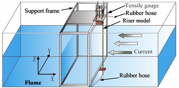
The riser model, 18 mm in diameter, 1.5 m long and with a slenderness ratio of 83.33, was tested in conditions in which the upper 0.75 m was in air, while the lower 0.75 m was exposed to a uniform current. So, a semi-uniform current was formed along the length on the whole. The riser model was vertically installed, and was submerged in a semi-uniform current in order to research the patterns of energy transfer under stepped excitation along the length of riser in real sea state. Model materials were made of transparent poly with a wall thickness of 2 mm and an elastic modulus of 0.91 GPa. The riser model with FBG sensors and on trial, as illustrated in Fig. 2. The detailed parameters of the riser model in the present experiment are listed in Table 1.
Fig. 2The riser model
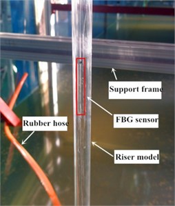
a) The riser model with FBG strain gauges
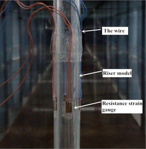
b) The riser model with resistance strain gauges
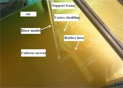
c) The riser model on trial (overwater)
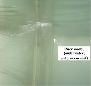
d) The riser model on trial (underwater)
Table 1Detailed parameters of the riser model
Total length () | 1.5 m |
Underwater length () | 0.75 m |
Overwater length () | 0.75 m |
Outer diameter () | 18 mm |
Inner diameter () | 14 mm |
Thickness () | 2 mm |
Modulus of elasticity () | 0.91 GPa |
Mass per unit length () | 0.12 kg/m |
Length/diameter ratio () | 83.33 |
Material () | Transparent poly |
The instrumented riser model was fixed by articulated support and allowed oscillations in both the in-line direction (-direction, IL) and the cross-flow direction (-direction, CF). The articulated support was specially made by machinery enterprise. To prevent initial top tension fluctuation at the beginning of the test, a locking device was installed on the outboard of the articulated support, and fastened after top tension was applied. Spiral manual tensile gauge was used to measure tensile variation during the experiment.
Fig. 3Design diagram of VIV test of the riser
a) Strain gauges arrangement along the riser
b) Cross section of the riser
c) Longitudinal section of the riser
Fig. 4Design diagram of the test that effect of internal flow velocity on top tension
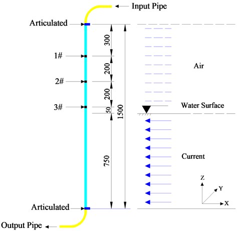
a) Strain gauges arrangement along the riser
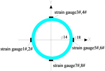
b) Cross section of the riser
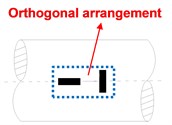
c) Longitudinal section of the riser
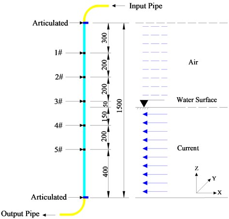
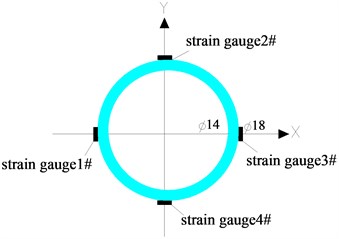
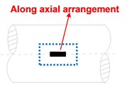
Two groups of riser model test were conducted synchronously. One is to study of VIV of risers under combined excitation of external flow, internal flow, and top tension, as shown in Fig. 3. Five measuring stations were installed along the length of the riser (Fig. 3(a)). Each station consisted of four FBG strain gauges arranged in an orthogonal matrix (Fig. 3(b) and (c)). The two strain gauges on the -axis were used to measure IL oscillation while those on the -axis were used to measure CF oscillation. After they were mounted on the surface of the riser, the gauges were coated with waterproof adhesive.
Another test is to study of the effect of internal flow velocity on the top tension of risers, as shown in Fig. 4. Three measuring stations were installed along the length of the riser. Each station consisted of four pairs of (i.e. eight) strain gauges arranged in the same way (Fig. 4(b) and (c)), and connected in a full-bridge manner to preclude any bending strain, and directly obtain the axial tensile or compressive strain of the riser. And the variation of the average value of top tension was yielded using stress and strain formulae. Fig. 5 shows the test data acquisition system used for acquiring bending strain and top tension variation data.
Fig. 5The test data collection systems
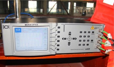
a) SI 425 fiber optical sensing extension modules for acquiring bending strain

b) Dynamic resistance strain gauge and data acquisition instrument for measuring the change of top tension
Table 2Working conditions of the riser model
Flow | Upper part | Lower part | Boundary conditions | Model material | Initial top tension | Internal flow velocity | Riser attitude | Sampling time |
Semi-uniform current | Air | 0-0.8 m/s uniform current | Articulated | Transparent poly | 17 N | 0-4.5 m/s | Standing | 40 s |
The external flow velocity ranges from 0 to 0.8 m/s, with approximate increments of 0.1 m/s, was measured using the Acoustic Doppler Current Profiler (ADCP). The process of external flow velocity collection was monitored during the whole experiment history to confirm the uniformity of flow. The strain signal was collected by Fiber Bragg Grating Signal Demodulator with sampling frequency 250 Hz. To prevent potential impact of unstable external flow on the dynamic responses of the riser, sampling started after each level of the velocity became stable, and lasted 40 seconds. The detailed working conditions of the riser model in the experiment are listed in Table 2.
3. Strain signal data analysis theory based on articulated boundary
Frequency spectrum analysis represents a basic analysis method for signal processing. The time domain signals obtained are subject to Fourier conversion and frequency domain information is obtained. The positive transformation equation is shown as follows:
where, ; means time domain data series; and means spectrum function series of frequency domain. As Fourier transformation is continuous in itself, the fast Fourier transformation (FFT) was adopted for solution. Due to frequency resolution and limited length of time domain signals, the FFT analysis result may have the probability of leakage. Thus, “windowing” measures were adopted for elimination.
A model analysis method has been used to study modal characteristics, dimensionless displacement and amplitude of the risers under different test conditions. The original intent was to use only the measured strains in the model analysis. For the riser structure of articulated model, some of the variables are assumed as follows. axis is in-line direction, axis is cross-flow direction and axis is vertical along the riser, the length of the riser is , the displacement of the riser is at any time . So, based on the modal decomposition of structural dynamics theory, displacement of the riser can be represented as follows:
where denotes the mode function, is the modal weights.
The relation between bending strain and curvature can be represented as follows:
where is the riser outer radius, the curvature is approximately equal to the second derivative of in direction:
Eq. (2) substituted into Eq. (3):
is the highest mode of the riser. is the number of measuring points along the riser length.
Eq. (5) can be transformed into matrix form:
The Eq. (6) can be expressed as follows:
For the riser structure of articulated model, the mode function can be expressed as a sine function:
So, the displacement function can be expressed as:
Eq. (9) substituted into Eq. (7):
Modal weights can be solved by the solutions of Eq. (10). Modal weights substituted into Eq. (9), and then the displacement time history along the riser can be attained.
4. The effect of internal flow velocity on natural frequency of the riser
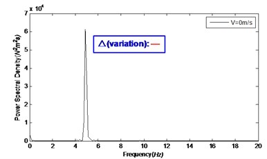
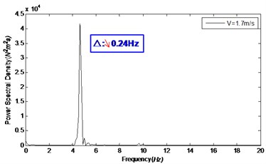
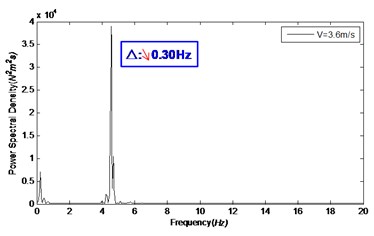
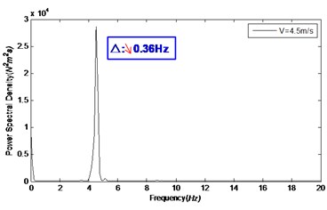
In order to measure the natural frequency of risers under different internal flow velocities, FBG decay signals were obtained through external load excitation by placing the riser model in still water, and applying different levels of internal flow velocity while keeping all other influencing factors unchanged. Out of these signals, the power spectral density of the riser model was derived. This way, the natural frequencies of risers under different internal flow velocities were yielded by FFT of the respective strain signals.
Fig. 6Natural frequency of the riser model under different internal flow velocities
a)0 m/s
b)1.7 m/s
c)3.6 m/s
d)4.5 m/s
Fig. 6 shows the natural frequency of the riser model under different internal flow velocities. At internal flow velocity of 0, 1.7, 3.6, and 4.5 m/s, the corresponding natural frequencies were 4.88, 4.64, 4.58, and 4.52 Hz, respectively. This suggests that increase of internal flow velocity lead to significant decrease of the natural frequency. And; the rangeability of natural frequency of risers depends on the magnitude of internal flow velocity. As can be inferred from the theoretical formula in literature [20], increase of top tension will lead to significant increase of the natural frequency of risers.
Hence, the internal flow velocity and top tension have some interconnection influences on the natural frequency of risers: increase of the former reduces their natural frequency while increase of the latter increases their natural frequency. That is, the natural frequency of risers is subjected to mutual inhibition between internal flow and the top tension of risers.
5. The effect of internal flow velocity on VIV process of the riser
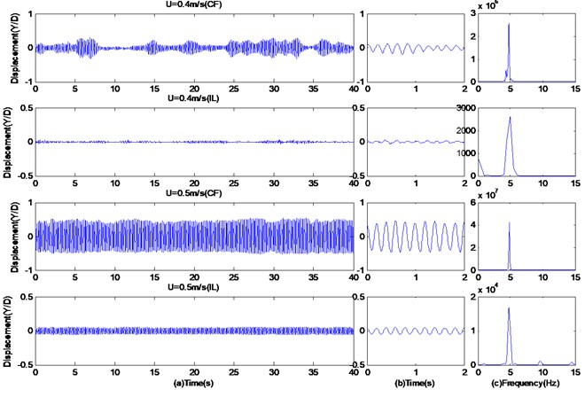
According to the VIV theory, if the frequency of a riser is close to that of vortex shedding, oscillation will result in the vortex shedding frequency being fixed at a point near the structure's natural frequency and cause large-amplitude vibration referred to as “lock-in” state. When the applied external flow velocity was 0.5 m/s, the vortex shedding frequency was about 4.91 Hz, as shown in Fig. 7(c), which is quite close to the natural frequency of the riser in still water (approximately 5.0 Hz). Obvious “lock-in” was observed at this time.
Fig. 7 shows the time histories of the CF and IL displacement/diameter and frequency spectrogram of the riser model under external flow velocities 0.4, 0.5 m/s. Here, is the outer diameter of the riser model, is the transient displacement of the riser obtained by transforming the strain time history data collected during the experiment using modal analysis theory as mentioned before; is the dimensionless displacement. Fig. 7(a) shows the whole run, and Fig. 7(b) is an enlargement of two seconds of the signals. From Fig. 7, it is obvious that the amplitude of CF displacement is about one order greater than the IL displacement; before “lock-in”, The oscillation frequency of -motion was 4.61 Hz when the external flow velocity was 0.4 m/s, and it increased to 4.91 Hz when the external flow velocity was 0.5 m/s.
Fig. 7Time histories of the CF and IL displacement/diameter and frequency spectrogram under external flow velocities are 0.4, 0.5 m/s
In order to verify the “lock-in” state of risers and the nonuniformity of its time series, CF and IL time-frequency plots of the riser model at the external flow velocities of 0.4 m/s and 0.5 m/s were yielded through Morlet Wavelet analysis (Fig. 8). From these plots, it is obvious that, within the sample interval, and when 0.4 m/s, the oscillation frequency was of the order of 4.6 Hz, the vibration intensity was not uniform, and there were two discontinuous points. The riser’s vibration frequency has a wide longitudinal distribution. when 0.5 m/s, the riser vibration demonstrated good continuity, and it can be seen from the time frequency plots that there is a narrow longitudinal distribution and high vibration intensity within the time domain. Obvious “lock-in” is observed. From Fig. 8, it is also obvious that, when 0.4, 0.5 m/s, the participation of high order frequency was presented in the IL time-frequency plots, with lower vibration intensity, as shown in the red rectangular dotted frame. But the phenomenon is not clearly reflected in the frequency spectrogram of Fig. 7(c).
Fig. 8The CF and IL time-frequency plots for external flow velocities 0.4, 0.5 m/s, which were obtained using the wavelet analysis


When 0.5 m/s, the vibration amplitude was much greater than when 0.4 m/s, and remained in a high-vibration state afterwards. Fig. 9 shows the CF amplitudes of five measuring points along the length of the riser model under different external flow velocity, which are quite consistent with each other except marginal differences in the amplitude: the displacements at points closer to the midspan are greater.
As illustrated also by Fig. 9, when the external flow velocity was smaller than 0.5 m/s, the displacement increase with external flow was slow; when the external flow velocity was in the 0.5-0.6 m/s range, the reduced velocity was about 5.6-6.7, and “lock-in” occurred; when the external flow velocity was greater than 0.65 m/s, the response of the riser jumped out of the “lock-in” region, and the amplitude dropped steeply. Fig. 9 also displays gradual amplitude increase from the endspan toward the midspan of the riser.
Fig. 9The CF amplitude of five measured stations along the riser length under different external flow velocity
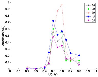
Fig. 10The CF amplitude of feature point of the riser model under different internal flow velocity accompanying external flow velocity process
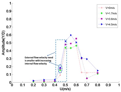
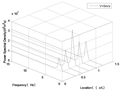
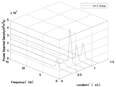
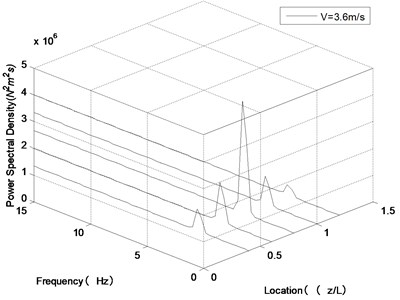
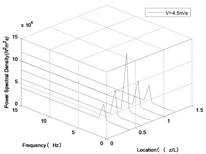
Fig. 11Frequency spectrogram of transverse vibration along the riser length at U= 0.5 m/s under different internal flow velocities
a)0 m/s
b)1.7 m/s
c)3.6 m/s
d)4.5 m/s
In order to research the effect of internal flow velocity on VIV process of the riser, the CF amplitude of feature point and three-dimensional frequency spectrogram of transverse vibration along the riser length under different internal flow velocity accompanying external flow velocity process were attained, which were illustrated in Fig. 10 and Fig. 11.
As shown in Fig. 10, compared with the working condition that internal flow velocity was 0 m/s, the overall trends of the curves of the other three working conditions (1.7 m/s, 3.6 m/s and 4.5 m/s) were similar as the external flow velocity increases. And the effect of internal flow velocity on VIV process is more significant in the interval of “lock-in” region. However, as shown in Fig. 11, at external flow velocity 0.5 m/s with internal flow velocity 0, 1.7, 3.6 and 4.5 m/s, the oscillation frequencies are 4.91, 4.76, 4.61 and 4.54 Hz, respectively. So, it can be inferred that with increasing internal flow velocity, the oscillation frequency of the riser decreases obviously, which means the “lock-in” state will occur at a low external flow velocity compared with internal flow velocity 0 m/s. The internal flow velocity is larger, corresponding oscillation frequency is smaller, which means external flow velocity that “lock-in” state need is smaller, with increasing internal flow velocity.
According to Fig. 10, the above argument details are strongly reinforced. Compared with internal flow velocity 0 m/s, the amplitude of other working conditions (1.7, 3.6 and 4.5 m/s) develops a mutation at 0.45 m/s, and the “lock-in” region moves to the left of axis, as shown in the blue dotted frame. It is also found that the larger internal flow velocity, this phenomenon is much more obvious.
6. The effect of internal flow velocity on top tension
Based on these analyses, it can be found that the internal flow velocity and top tension have some interconnection influences on the VIV characteristics of the riser. For the purpose of comparison, the effect of internal flow velocity on VIV amplitude of the risers coupling of top tension and the effect on top tension are analyzed in this section.
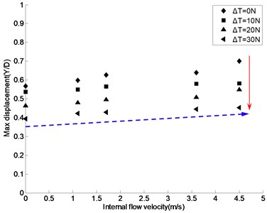
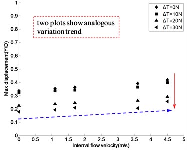
Fig. 12 shows the maximum CF displacement/diameter under different internal flow velocities ( 0, 1.1, 1.7, 3.6, and 4.5 m/s), different top tension ( 0, 10, 20 and 30 N), and external flow velocities ( 0.6, 0.7 m/s). As the vibration of the riser model was in the “lock-in” region when the external flow velocity was 0.6 m/s, and jumped out of this region when the external flow velocity was 0.7 m/s. The corresponding displacements shown in Fig. 12(a) are greater than those in Fig. 12(b). But the two plots are still comparative, and both show a significant displacement decline with the increase of top tension: in Fig. 12, it can be seen that with the top tension increasing, the amplitude decreases obviously. The mean value of the displacements decreases 0.15D with each grade top tension in Fig. 12(a), and in Fig. 12(b) it is 0.1D. Thus, it can be seen, top tension plays a great role in the vibration amplitude of the riser model.
Fig. 12The curves of the effect of top tension and internal flow velocity on displacement of the riser model under external flow velocity 0.6, 0.7 m/s
a)0.6 m/s
b)0.7 m/s
From Fig. 12, we can also observe that, as internal flow velocity increases, so does the displacement of risers, though at a smaller rate of variation than that caused by top tension. When the top tension is relatively small, the effect of internal flow velocity on displacement is significant; as top tension increases, the effect of internal flow velocity becomes less significant. For example, when 0 N, and V = 0, 1.1, 1.7, 3.6 and 4.5 m/s, the displacements were 0.56D, 0.59D, 0.62D, 0.64D, and 0.71D, respectively. when 30 N, the displacements were 0.39D, 0.42D, 0.43D, 0.45D, and 0.46D, respectively.
Fig. 13Variation of top tension under different internal flow velocity
a) Variation of top tension
b) Alterant value of top tension
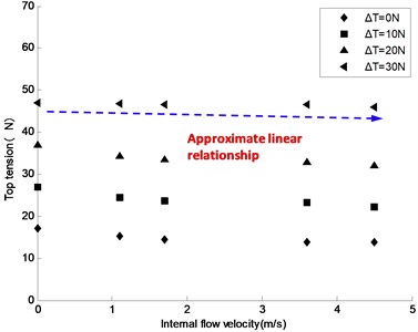
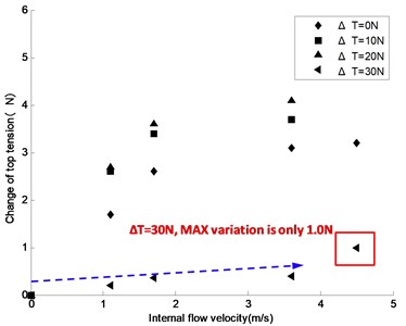
Fig. 13 shows the top tension variation of the riser model induced by internal flow velocity under different initial top tensions. Fig. 13(a) shows the top tensions acquired during the experiment under different internal flow velocities. Fig. 13(b) shows the top tension variation from the initial level under different internal flow velocities. As can be observed from these plots, under a small initial top tension (when 10 N, for example), the effect of internal flow velocity on top tension is significant; as internal flow velocity increases, top tension gradually decreases. When 10 N, for example, and top tensions under the internal flow velocities of 1.1, 1.7, 3.6, and 4.5 m/s were 24.4, 23.6, 23.3, and 22.2 N, representing a decrease of 2.6, 3.4, 3.7, and 4.8 N from the initial level, and the averaged top tension variation was 36 percent of the initial level; when 20 N, the top tensions under the internal flow velocities of 1.1, 1.7, 3.6, and 4.5 m/s were 34.3, 33.4, 32.9, and 32.1 N, representing a decrease of 2.7, 3.6, 4.1, and 4.9 N from the initial level, and the averaged top tension variation was 19 percent of the initial level.
When 30 N, the effect of internal flow velocity on top tension became much weaker unexpectedly. In Fig. 13(a), when 30 N, the top tension profile was almost a straight line except a significant fluctuation at the internal flow velocity of 4.5 m/s. In Fig. 13(b), the top tension variations under the internal flow velocities of 1.1, 1.7, 3.6, and 4.5 m/s were 0.2, 0.4, 0.36, and 1.0 N; the averaged top tension variation was only 1.6 percent of the initial level. This also verifies that, under a high initial top tension, internal flow does not make much difference to top tension.
7. Conclusions
The experimental research of the effect of internal flow velocity on VIV characteristics of top tension risers in a semi-uniform current was conducted through two kinds of data testing systems. By changing internal flow velocity, the effect on dynamic characteristics and dynamic responses of the riser were studied. The effect of internal flow velocity on the amplitude of the riser with different initial top tension and the effect of internal flow velocity on the top tension were mainly analyzed. Based upon the test results, the following conclusions can be drawn.
The natural frequency of risers is subject to significant mutual inhibition between internal flow and top tension. Increase of internal flow velocity leads to gradual decrease of riser natural frequency, especially in the “lock-in” region, and pushes this region towards low frequencies. That is, relatively low external flow velocities will force a riser into the “lock-in” state earlier than usual, hence high internal flow velocities are a matter of security concern during the service of risers. Increase of internal flow velocity leads to gradual increase of riser displacement, though at a smaller rate of variation than that caused by top tension. Especially the top tension is relatively small, the effect is obvious. And the top tension gradually decreases with the increase of internal flow velocity under relatively small initial top tension. This suggests that internal flow velocity can offset some of the riser responses induced by top tension except when the initial top tension is high, in which case internal flow velocity does not make much difference to top tension.
References
-
Song J. N., Lv L., Zhang J. Q., Wu H., Tang G. H., Li G. W., Teng B., Zhao R. H. Experimental investigation of suppression of vortex-induced vibration of marine risers by three control rods. The Ocean Engineering of China, Vol. 27, Issue 3, 2009, p. 23-29.
-
Jiao B. T., Jia X., Cao J., Zhang X. L., Yang J. D. The study and development of a vortex-induced vibration suppression device for deepwater riser. China Offshore Oil and Gas, Vol. 24, Issue 3, 2012, p. 70-75.
-
Baarholm G. S., Larsen C. M., Lie H. Reduction of VIV using suppression devices - an empirical approach. Marine Structures, Vol. 18, 2005, p. 489-510.
-
Gao Y., Fu S. X., Song L. J. Experimental investigation on the suppression device of VIV of a flexible riser. Journal of Vibration and Shock, Vol. 33, Issue 14, 2014, p. 77-83.
-
Huang S., Herfjord K. Experimental investigation of the forces and motion responses of two nterfering VIV circular cylinders at various tandem and staggered positions. Applied Ocean Research, Vol. 43, 2013, p. 264-273.
-
Moe G., Chucheepsakul S. The effect of internal flow on marine risers. Proceedings of 7th International Conference on Offshore Mechanics and Arctic Engineering, Tokyo, Japan, 1988, p. 375-382.
-
Paı¨doussis M. P., Grinevich E., Adamovic D., Semler C. Linear and nonlinear dynamics of cantilevered cylinders in axial flow, Part 1: Physical dynamics. Journal of Fluids and Structures, Vol. 6, 2002, p. 691-713.
-
Lopes J. L., Paı¨doussiss M. P., Semiler C. Linear and nonlinear dynamics of cantilevered cylinders in axial flow, Part 2: The equations of motion. Journal of Fluids and Structures, Vol. 16, 2002, p. 615-737.
-
Semler C., Lopes J. L., Augu N., Paı¨doussis M. P. Linear and nonlinear dynamics of cantilevered cylinders in axial flow, part 3: Nonlinear dynamics. Journal of Fluids and Structures, Vol. 16, 2002, p. 739-759.
-
Chen B. C. M. A marine riser with internal flow velocity-induced vibration. Proceedings of Offshore Technology Conference, Houston, USA, 1992.
-
Hong N. S. The Effect of Internal Flow Velocity on Marine Riser Dynamics. Ph.D. Dissertation, University of Florida at Gainesville, USA, 1994.
-
Hong N., Huh T. The effect of internal flow velocity on vortex-induced vibration of riser. Proceedings of the Ninth International Offshore and Polar Engineering Conference, Brest, France, 1999, p. 688-693.
-
Li X. M., Guo H. Y., Meng F. S. Effect of internal flow on the dynamic behavior of top tensioned riser. Journal of Ship Mechanics, Vol. 14, Issue 9, 2010, p. 1021-1030.
-
Guo H. Y., Lou M. Effect of internal flow on vortex-induced vibration of risers. Journal of Fluids and Structures, Vol. 24, 2008, p. 496-504.
-
Lee K. Q., Aminudin A., Naomi K., Pauziah M. Investigation on the effectiveness of helical strakes in suppressing VIV of flexible riser. Applied Ocean Research, Vol. 44, 2014, p. 82-91.
-
Zhang Y. B., Guo H. Y., Meng F. S., et al. Model tests for vortex-induced vibration of a top tension riser based on wavelet transformation. Journal of Vibration and Shock, Vol. 30, Issue 2, 2010, p. 149-154.
-
Wang J. G., Fu S. X., Xu Y. W, et al. VIV developing process of a flexible cylinder under oscillatory flow. Chinese Journal of Theoretical and Applied Mechanics, Vol. 46, Issue 2, 2014, p. 173-182.
-
Huera-Huarte F. J., Bearman P. W. Vortex and wake-induced vibrations of a tandem arrangement of two flexible circular cylinders with near wake interference. Journal of Fluids and Structures, Vol. 27, 2011, p. 193-211.
-
Chaplin J. R., Bearman P. W., Huera-Huarte F. J., Pattenden R. J. Laboratory measurements of vortex-induced vibrations of a vertical tension riser in a stepped current. Journal of Fluids and Structures, Vol. 21, Issue 1, 2005, p. 3-24.
-
Lie H., Kaasen K. E. Modal analysis of measurements from a large-scale VIV model test of a riser in linearly sheared flow. Journal of Fluids and Structures, Vol. 22, Issue 4, 2006, p. 557-575.
About this article
This work is supported by Shang Dong Province Young and Middle-Aged Scientists Research Awards Fund (BS2015HZ017), Colleges and Universities of Shandong Province Science and Technology Plan Projects (J16LH04), the Opening Project Fund of Shandong Provincial Key Laboratory of Civil Engineering Disaster Prevention and Mitigation (CDPM2013ZR01) and Qingdao postdoctoral researchers applied research Project (01020120406).
