Abstract
This research examines the emerging role of adaptive interval type-2 fuzzy logic systems (AIT2FLS) versus adaptive type-1 fuzzy logic system (AT1FLS) in vehicle handling by a new nonlinear model of the variable geometry suspension system (VGS) as a vehicle active suspension system. A proper controller is needed in order to have soft response and robustness against challenging vehicle maneuvers. Two controllers, including AT1FLS and AIT2FLS have been used in the paper. The proposed AIT2FLS can efficiently handle system uncertainties, especially in the presence of most difficult challenging vehicle maneuvers in comparison with AT1FLS. The interval type-2 fuzzy adaptation law adjusts the consequent parameters of the rules constructed on the Lyapunov synthesis approach. For this purpose, the kinematic equations are obtained for the vehicle double wishbone suspension system and they are substituted in a nonlinear vehicle handling model with eight degrees of freedoms (8DOFs). Thereby, a new nonlinear model for the analysis of VGS is obtained. The results indicate that between the two controllers, the proposed AIT2FLS has better overall vehicle handling, robustness and soft response.
1. Introduction
Adaptive control is one of the most widely used methods in uncertain system controller design. It provides a mechanism to adjust the controller’s parameters against system uncertainties and disturbances using some adaptation laws. However, it usually needs an initial model of the system. In contrast, fuzzy logic is a recent method used in many papers [1-3] which provides a valuable tool to utilize human experts’ knowledge completing our mathematical knowledge. However, this technique suffers from the lack of a mechanism to determine the consequent membership functions. Therefore, a hybrid combination of adaptive control and fuzzy logic presents an attractive and powerful approach to design controllers.
AIT2FLS in recent years, because of their potential to model and cope with dynamic uncertainties and disturbances, have attracted interest of many researchers. Wang [1] designed a direct adaptive fuzzy logic controller and used the Lyapunov theory to acquire adaptive rules. He used the same theory to present a general solution to the problem of a stable adaptive fuzzy logic controller [2]. Then he used the controller in two degrees of freedom inverted pendulum. Next, Tang [3] designed an adaptive fuzzy logic controller based on nonlinear system model inputs and outputs. Shahnazi and Akbarzade [4] introduced a proportional-integral (PI) indirect adaptive fuzzy logic controller versus a routine adaptive fuzzy logic controller, which speed up responses near the equilibrium point.
In 2007, Wai [5] proposed an adaptive fuzzy sliding mode controller and successfully demonstrated its application to an indirect field-oriented induction motor drive for tracking periodic commands. Moreover, he utilized fuzzy inference mechanism in order to implement a fuzzy hitting control law to remove the chattering phenomenon. In [6], sliding mode control and fuzzy systems as universal estimators were used to control a class of under actuated systems. They used an adaptive law to improve the approximation accuracy and guarantee the tracking performance. In 2010, Tie-Shan [7] introduced a novel robust adaptive Takagi-Sugeno fuzzy logic tracking control for nonlinear systems. Their method reduced the number of parameters updated online for each subsystem to one. Tsung-Chih et al. [8] proposed an adaptive fuzzy sliding mode controller for the synchronization of two different uncertain fractional-order time-delay chaotic systems. They used the Lyapunov stability criterion to show that free parameters of the adaptive fuzzy sliding mode controller can be tuned online by the output-feedback-control law and adaptive law. Hongyi Li et al. [9] focused on designing a sampled-data controller for interval type-2 fuzzy logic system (IT2FLS) with actuator fault in such a way that the actuator fault of IT2FLS is considered. They showed the resulting closed-loop system to be reliable since the designed controller can guarantee the asymptotic stability and H∞ performance when the actuator experiences failure. A direct adaptive general type-2 fuzzy controller is introduced by Ghaemi et al. [10] for a class of uncertain nonlinear systems. It is compared with the direct adaptive type-1 fuzzy logic controller and direct adaptive interval type-2 fuzzy logic controller, and its effectiveness is illustrated by simulation with the integration of dynamic uncertainties and external disturbances. Tsung-Chih [11] showed that the linguistic fuzzy control rules could be directly joined to the controller and used with the attenuation technique.
Currently, many researchers have focused their research efforts on the study of handling vehicle dynamic control systems. Some automotive companies have modified the vehicle’s stability and handling control system in order to avoid the vehicle from spinning or drifting out [12]. The geometry of the vehicle suspension system has a main role in the stability and handling of the vehicle. In the VGS, the actuating force can be made perpendicular to the wishbone direction, and this is a privilege of this type of system [13-17]. The researchers to date have tended to focus on the VGS, but they did not have an analytical model for the VGS. We can develop a new VGS nonlinear model by combining the kinematics of the vehicle’s suspension system and the vehicle’s handling model.
From the 1980s to 1990s, and even up to the present time, a large number of papers was published regarding vehicle active suspensions, making it a hot issue in the industry. The research studies that were conducted over the past two decades were resulted in many patents. However, not all of the products were of good quality [18-22].
The Velocette Thruxton motorcycle is the first variable geometry suspension system in which the ratio of wheel movement to spring movement can be manipulated manually [13]. Watanabe and Sharp [15] used the optimal-PD (proportional-derivative) and Neuro-controllers acting together, and the end positioning of the spring and damper to the wishbone changed that it could decrease body roll and the roll centre height alteration. Lee et al. [16] increased the vehicle handling characteristics by using a VGS, which three suggested points were selected in the McPherson suspension. Evers et al. [23] presented a new VGS model with actuator forces which is used in the Delft model, and they indicated that the power consumption of the actuator is evaluated under the worst case conditions. Goodarzi et al. [24] used the ADAMS software to give a multi-linked suspension’s mounting point variation directly related to the roll centre height and toe angle and produced an approximate model for VGS. Their work showed that the PI-Fuzzy controller usage improved the vehicle stability and handling.
There are many uncertainties such as plant model, unpredictable environmental changes, unreliable sensor information and actuators malfunction in vehicles. Therefore, intelligent controllers can move the suspension mounting point’s positions in the VGS very well. This provides the best condition for vehicle dynamics with low energy consumption. The displacement zone of the vehicle’s suspension system is limited, and the vehicles dynamics are variable due to VGS. Therefore, the suspension mounting point displacement (SMD) should be changed by advanced and intelligent controllers.
Nemeth and Gaspar [25] improved vehicle dynamics using a VGS with a controller design based on the robust linear parameter varying method. To determine the effects of adaptive fuzzy logic control (AFLC) on vehicle dynamics, Baghaeian and Akbari compared AFLC and proportional-integral-derivative (PID) in VGS and showed that AFLC has improved parameters of stability [26]. Nemeth and Gaspar [27] propose a method in which the structure of a variable geometry suspension system and the design of a robust control are achieved simultaneously in order to improve vehicle stability. Also, Gaspar analyzed the efficiency of the variable geometry suspension in preliminary works in the coordination of steering and wheel tilting [28]. Zirkohi and Lin [29] offered a new IT2FLS with neural network and indirect adaptive with sliding mode control methodology for a vehicle suspension system including actuator that the novel hybrid control approach was suggested to address controlling active suspension systems including actuator dynamics without chattering phenomenon in the face of structure and unstructured uncertainties.
The main contributions of this paper are: 1) The vehicle performance is modified by using the proposed AIT2FLS in VGS in contrast to the AT1FLS. 2) Use of the Lyapunov synthesis to guarantee stability and to find adaptation laws. 3) A new VGS nonlinear model is produced for vehicle handling analysis by using the kinematics formula of the double wishbone suspension system in the 8DOFs vehicle handling nonlinear model.
This paper is organized as follows: Section 2 presents a brief introduction to the proposed AIT2FLS. The proposed method of the controller structure under consideration here in presented in Section 3 and the underlying assumptions based on the theory of AIT2FLS are proved in that section. A new analytical nonlinear model of VGS is introduced in Section 4. The VGS model is simulated under the two standard maneuvers with the details presented in Section 5. To be fair, the proposed controllers are compared with similar metrics in Section 5.
2. Interval type-2 fuzzy logic systems
A general type-2 fuzzy set is given below:
where μ˜A(x) and fx(v) denote the secondary membership function (MF) and the secondary grade, respectively; Jx denotes the domain of the secondary MF and v is a fuzzy set (FS) in the interval [0, 1]. If fx(v)= 1 for, ∀v∈Jx then secondary membership functions are said to be interval sets.
The resulting FS is an interval type-2 fuzzy set which is determined as follows:
Due to the computational complexity, many researchers use interval type-2 fuzzy sets (IT2FS) instead of general type-2 sets, interval type-2 fuzzy set [6, 8, 11, 30, 31]. An IT2FS can be simply described in terms of its lower μ_˜A(x) and upper ¯μ˜A(x) membership functions (MFs). The area enclosed by upper and lower MFs is called as the footprint of uncertainty (FOU) which is expressed as:
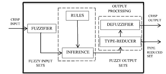
Fig. 2 shows the typical structure of IT2FLS with their fuzzifier, fuzzy rule base, fuzzy inference engine, type reducer and defuzzifier. Fig. 2 shows the general structure of IT2FLS which is described as follows.
The fuzzifier represents real valued variables as fuzzy sets. It includes the expert knowledge consisting of a set of fuzzy IF-THEN rules.
The jth rule of the IT2FLS is described as:
where M is the number of rules; xi (i=1, 2,…, n) and y respectively denote the input and output sets of the IT2FLS; ˜Fjn and ˜Gj respectively denote the antecedents and the consequent fuzzy sets.
Fig. 1Indicates a type-2 fuzzy MF with its FOU, upper and lower bounds and standard deviation (δ1, δ2)
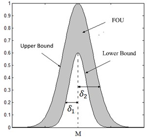
Fig. 2General structure of IT2FLS
In order to produce output IT2FS, reception of inputs and their combination with the fuzzy rules should be conducted by the inference engine. Thus, the firing set is provided as:
The firing sets of IT2FS can be written with upper and lower MFs:
where f_j(X) and ¯fj(X) are the lower and upper MFs of jth, respectively; and * defines the Mamdani t-norm. Given that the output of the inference engine is a type-2 fuzzy set, it is necessary to use a type reducer before defuzzification converting the type-2 fuzzy sets into type-1 fuzzy set. Five different type reducers have been proposed by Karnik and Mendel in [32]. Center of sets (COS) is mostly used among these due to its computational simplicity by the Karnik-Mendel (KM) iterative algorithm [32-34]. COS type reducer can be represented as:
where fj∈Fj=[f_j(X),¯fj(X)] and θj denotes the centroid of jth consequent set. In general, the type reducer gives the output as an interval set being demonstrated with its left-end and right-end points (i.e. yl and yr).
These points cannot directly be computed with mathematic formulas. However, the KM iterative algorithm has been introduced to calculate them by Mendel and Karnik in [35]. Now yl and yr can be written as:
where θjl and θjr are the left-end and right-end point of jth consequent set, respectively. L and R are the breaking point being determined by the KM algorithm. Here:
θr=[θ1r,…,θMr]T,ξjr=fjr∑Rj=1f_j+∑Mj=R+1¯fj,ξr=[ξ1r,…,ξMr]T.
Since IT2FS is used here, the output of defuzzified blocks can be easily obtained by averaging, yland yr [33] as follows:
3. Direct adaptive interval type-2 fuzzy logic control
The following general class of single input- single output (SISO) nonlinear systems can be considered for [4]:
where f and g are unknown nonlinear dynamics; t is time; u and y respectively denote the input and output of the system; and X_=[x,˙x,…,x(n-1)]=[x1,x2,…,xn] represents the state vector of the system. In Eq. (14), d(t) represents the external disturbance which is supposed to be bounded by an unknown constant D, i.e.
In order to track the desired state vector X_d=[xd,˙xd…,xd(n-1)] by the state vector X_ with existing disturbances and function uncertainties, the tracking error should be defined as follows:
The nonlinear system in Eq. (14) can be rewritten by some simple manipulation:
where:
If f and g in Eq. (17) are nonlinear known dynamics and d(t)=0, then the asymptotic error can converge to zero by the following controller:
where C=[cn,…,c1] represents a constant vector that is selected to make the polynomial h(λ)=λ(n)+c1λ(n-2)+…+cn Hurwitz. The controller is robust if the following H∞ condition is satisfied [36]:
where V denotes the Lyapunov function, ρ>0 is the level of prescribed attenuation and Q is an arbitrary positive definite matrix. In general, f and g are nonlinear unknown dynamics and the disturbance d(t) creates negative effects. Since the fuzzy logic systems are considered as general approximators, u* can be replaced with an interval type-2 fuzzy approximation as ˆu(x|θ). In order to reduce the effect of the external disturbances, the H∞ compensator is required. Then the resulting controller is given as:
where ˆu(X_|θ) and uhrespectively denote AT2FLS and H∞compensator.
Theorem. If the following adaptive laws and H∞ compensator are satisfied, the stability of the system in Eq. (14) will be guaranteed by the control input u in Eq. (21) and H∞ tracking performance in Eq. (20) will be achieved:
where γ1 and γ2 are positive constants. P is a positive definite matrix being obtained by solving the following Riccati-like equation:
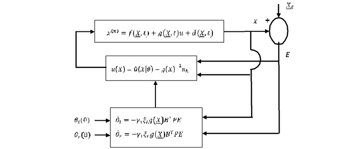
The schematic of the proposed direct adaptive interval type-2 fuzzy logic controller (DAIT2FLC) is depicted in Fig. 3.
Fig. 3Schematic of DAIT2FLC
Proof: Consider the following optimal consequent parameters for fuzzy system:
The minimum approximation error is expressed as:
By using control input in Eq. (21) and the nonlinear system in Eq. (17), we have:
The following relation is obtained from Eq. (19):
Substituting Eq. (29) in to Eq. (28), it gives:
After manipulating Eq. (30) and using Eq. (16) and (17), we have:
=(A-BCT)E_+B[g(X_,t)(ˆu(X_|θ)-ˆu(X_,θ*))]-Buh+Bd(X_,t)+Bω.
Substituting Eqs. (11) and (12) in Eq. (31), it gives:
where:
Now the Lyapunov function is expressed as bellow:
The derivative of V with respect to time gives:
The following relation is provided by substituting Eq. (32) in to Eq. (34) and using the H∞ compensator in Eq. (24):
+12[E_TP(A-BCT)E_-1γ2E_TPBBTPE_+E_TPBg(X_,t)φTlξl+φTrξr+E_TPBωl]
+˙φTlφlγ1+˙φTrφrγ1.
Imposing the adaptive laws upon Eqs. (22), (23), and (25), we have:
=-12E_TQE_-12(1ρE_TPB-ρωl)(1ρE_TPB-ρωl)T+12(ρωl)2.
Considering,(1ρE_TPB-ρωl)(1ρE_TPB-ρωl)T≥0 it can be written:
Now, the integration of Eq. (37) is:
Considering V(t)≥0, we have:
and H∞ tracking performance in Eq. (20) is provided. Thus, the proof is complete.
Remark: g(X_,t) can be split into a well-known part g0(X_,t) and gu(X_,t) an unknown part. Then the unknown part can be regarded as the external disturbance part being compensated using the H∞ controller.
4. New model of variable geometry suspension systems in vehicle
4.1. Variable geometry of suspension system
VGS is one of the active suspensions that can play a key role in the characteristics of vehicle handling such as yaw rate and lateral acceleration. The schematic diagram of the double wishbone suspension is shown in Fig. 4 [37].
The roll center height is hR that is related to geometric parameters by Eqs. (40)-(45):
where Z is the SMD of the lower wishbone and the control input signal as u=Z, T is the vehicle track, k is the distance between P and G, β is the lower wish-bone angle, β0 is the initial angle of lower wish-bone, d is the G point height, σ is the kingpin angle, rσ is the scrub radius, k1 is the lower wish-bone length and p is the instantaneous center of rotation height that is expressed as bellow:
Fig. 4Centre of gravity height (h) and distance between centre of gravity and roll centre (H) are added by geometry of double wishbone suspension system [37]
![Centre of gravity height (h) and distance between centre of gravity and roll centre (H) are added by geometry of double wishbone suspension system [37]](https://static-01.extrica.com/articles/17862/17862-img4.jpg)
And we have:
where C1 is the kingpin length from front view and ∅1 is the upper wish-bone angle.
Also, for H we can write:
where h is the centre of gravity height and H is the distance between the centre of gravity and roll centre. Also, in Fig. 4 R is the roll centre point in the middle of vehicle.
From Eq. (40) and Eq. (44), H is obtained as follows:
Substituting H in to the equations of the vehicle’s dynamic model with 8DOF, yield a new model of VGS. Also, the geometry parameters of the suspension system and their values are presented as follows in Table 1.
Table 1Geometry data of vehicle suspension system
Variable | Unit | Value | Variable | Unit | Value |
β0 | deg | 11 | rσ | mm | 5 |
h | mm | 781 | c1 | mm | 280 |
σ | deg | 10 | k1 | mm | 370 |
∅1 | deg | 5 | h | mm | 220 |
4.2. 8DOFs vehicle handling nonlinear model
8DOFs vehicle dynamic model, shown in Fig. 5, is used as the working model. The degrees of freedom include the longitudinal and lateral velocity, yaw rate, roll angle, plus other four degrees of freedom that are the rotational speeds of the wheels. The model contains all the system nonlinearities, such as the nonlinear behavior of tires, the nonlinearities in the longitudinal and lateral tire normal load transfers, roll steer effect, and roll centre height variations.
The equations can be written in X, Ydirections and the consistent rotating motions of the roll and yaw around the X-axes and Z-axes are as follows.
X-direction:
Y-direction:
X-rotation:
where Fx is the longitudinal tire force, Fy is the lateral tire force, m is the vehicle total mass, ms is the sprung mass, Ixx is the sprung mass moment of inertia about x-axis, φ is the body roll angle, Kt is the total vehicle torsional stiffness, Ct is the total vehicle torsional damping coefficient and ax, ayu are the longitudinal and lateral accelerations of the un sprung mass as follows:
where r is the yaw rate, ux is the vehicle longitudinal speed and vy is the vehicle lateral speed.
Z-rotation:
where a is the distance between front axle to the vehicle centre of gravity, b is the distance between rear axle to the vehicle centre of gravity, T is the vehicle track and IZZ is the sprung mass moment of inertia about z-axis.
Fig. 5Vehicle’s 8DOFs dynamic model
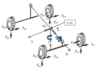
Fig. 6Longitudinal and lateral tire forces
Also for wheel spins, we have:
where Rt is the wheel radius, ω is the rotational speed of the wheel and Iω is the wheel moment of inertia.
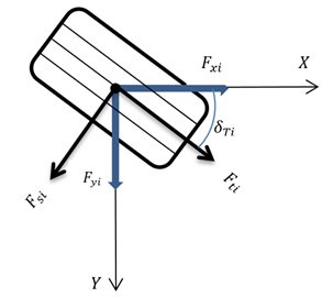
Longitudinal and lateral tire forces with respect to Fig. 6 can be produced as follows:
where δT is the steer angle and δT3, δT4 are equal zero in the rear steer angles. Ft, Fs are tire forces that are produced from nonlinear tire. Also, normal tire loads could be written as follows:
Fz2=W2[bl-axg(hl)-KR[ayg(hT)-(msm)(HT)sinφ]],
Fz3=W2[al+axg(hl)+(1-KR)[ayg(hT)-(msm)(HT)sinφ]],
Fz4=W2[al+axg(hl)-(1-KR)[ayg(hT)-(msm)(HT)sinφ]],
where W is the vehicle total weight, l is the wheel base and KR is the front roll stiffness per rear roll stiffness.
Also, ay is the lateral acceleration of sprung mass that could be written as follows:
Also, in Fig. 6 and we have the tire slip angle:
α3=tan-1br-vyux+Tr2,α4=tan-1br-vyux-Tr2,
where α is the tire slip angle.
Fig. 7 shows the structure of the vehicle model with 8DOFs in which the relationship is shown between sub-models, driver and control system is shown. In order to enhance vehicle handling, the SMD is controlled.
The nonlinear tire model used in this research is the Magic Formula tire model. The tire model defines the tractive and lateral tire forces based on its longitudinal wheel slip angle, normal force and tire slip angle.
Fig. 7Structure of vehicle model
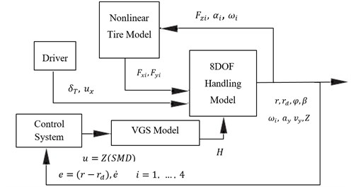
There are many vehicle dynamic models prepared with VGS. However, none of them is an analytical model. In order to develop an analytical model, Eq. (45) is substituted in Eqs. (47), (48), (55) and (56) and those manipulate as state-space equation. Then a vehicle dynamic model equipped with VGS is prepared to be used in the vehicle handling analysis. In this model steer angle and longitudinal velocity are treated as system inputs. Control inputs are e=(r-rd) and ˙e and control signal input is u=Z(SMD).
Data for a sport utility of the vehicle (SUV) and a kind of double wishbone suspension system is presented in Table 1 and 2. Finally, the model is validated with CarSim software that is a powerful software in vehicle dynamics.
Table 2Vehicle data
Variable | Unit | Value | Variable | Unit | Value |
m | kg | 1987 | l | m | 2.5780 |
ms | kg | 1662.065 | Kt | N.m/rad | 56957 |
mus | kg | 324.935 | KR | Dimensionless | 0.4 |
Ixx | kg.m2 | 657.2714 | Ct | N.m.s/rad | 3495.7 |
Izz | kg.m2 | 4510.3 | a | m | 1.1473 |
T | m | 1.4 | b | m | 1.4307 |
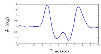
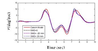
Fig. 8(a) shows the wheel angle of the system input as the double lane change (DLC) maneuver. Three suspension mounting point displacements (SMDs) are considered to be –20, 0 and 20 mm that SMD = 0 is equal to the CarSim model.
Fig. 8(b) is the yaw rate which illustrates the response of VGS model to be very close to the full CarSim model (SMD = 0). The vehicle dynamics model prepared with VGS is ready to be used.
Fig. 8Vehicle validation result
a) DLC maneuver steer angle
b) Yaw rate for DLC maneuver
5. Simulation results and analysis
Strong evidence of vehicle handling was found when the yaw rate and lateral acceleration were controlled. This could be achieved by tracking the desired yaw rate by controlling the SMD as structure of Fig. 7. The SMD is controlled by AT1FLS and AIT2FLS. Now in order to demonstrate the efficiency of the AIT2FLS, the proposed method is applied to the 8DOFs vehicle handling nonlinear model equipped by VGS as a case study.
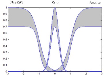
In AIT2FLS, the base of the fuzzy control information is made from a parabolic function of the MFs [38]. Hence, in AIT2FLS, for each control input e and ˙e, we defined three intervals type-2 fuzzy parabolic MFs: negative, zero, positive in the interval (–3 3), as illustrated in Fig. 9 and they are calculated as follows:
¯μP(e,˙e)=11+exp(-4(e+1)),μ_N(e,˙e)=0.71+exp(7(e+1)),
μ_Z(e,˙e)=0.7exp(-8e2),μ_P(e,˙e)=0.71+exp(-8(e+1)).
Fig. 9Input e and e˙ MFs for AIT2FLS
For evaluating the response of a computer control system, we can use the same criteria that are normally used in the adjustment of controller parameters. These are as follows:
(1) Integral of square error (ISE).
(2) Integral of the absolute value of the error (IAE).
(3) Integral of the time multiplied by the absolute value of the error (ITAE).
(4) The robustness of the proposed control scheme against fast changes and uncertainty must be high and it must be controlled by using the maximum error.
Now, the efficiency of the proposed H∞ adaptive interval type-2 fuzzy logic controller is verified by comparing the results with the direct adaptive type-1 fuzzy logic controller in terms of ISE, IAE and the maximum error metrics.
To distinguish between the possibilities of these controllers, the lane change (LC) and DLC maneuvers were used as common system inputs. Also, longitudinal velocity was used 50 km/h. The control inputs in AIT2FLS and AT1FlS are e and ˙e. So, in Eq. (16) X_ is the yaw rate and X_d is the desired yaw rate which can be written as follows [12]:
where δT is the steer angle, l is the wheel base and, Cαf, Cαr are the tire cornering stiffness in front and rear that is 35000 N/rad.
5.1. LC maneuver
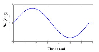
This maneuver is the challenging input for checking the vehicle handling by reducing the yaw rate and body lateral acceleration. In this maneuver, the steer angle is 4 degrees as shown in Figs. 10(a).
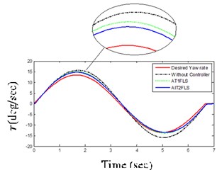
AIT2FLS responses in Figs. 11(a) and (b) indicate that the yaw rate and body acceleration has been dropped which shows that the vehicle handling characteristics are improved by using the controllers. In addition, the usage of human expert knowledge in fuzzy systems further improves the ISE and IAE as shown in Table 3 and Figs. 12(a) and (b). In other words, the ISE and IAE for the proposed AIT2FLS are less than 0.0016 and 0.096, whereas they are higher than 0.0020 and 0.104 for the AT1FLS, respectively.
According to Table 3, ISE, IAE and the maximum absolute error in AIT2FLS are less than that of AT1FLS that are around 20 %, 8 % and 19 % deceleration. The AIT2FLS has criteria for successful operation when compared to other controllers.
5.2. DLC maneuver
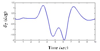
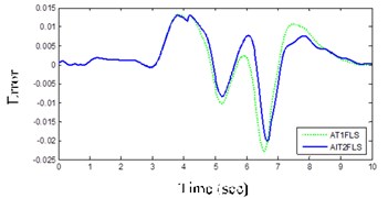
One of the most distinguished tests for vehicle handling and stability is DLC maneuver [25]. It has been used to investigate the controller’s performance in difficult vehicle conditions. Figs. 11(c) and (d) illustrate that AIT2FLS responses have tracked the desired response every time when compared to the AT1FLS.
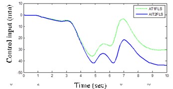
Fig. 13(d) illustrates that variation of the control input signal in AIT2FLS is small and the response is soft against another controller.
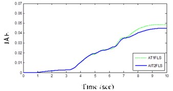
One of the important factors for the selection of controllers is a small ISE and that AIT2FLS has a lower ISE of about 0.0004 in the case of DLC maneuver according Table 3 and Fig. 13(a).
Also, other factors for assorting the controllers are the IAE and maximum absolute error that Figs. 13(b) and (c) illustrate, respectively. In all of them, AIT2FLS has respectable conditions that are about 0.044 and 0.020, whereas those for the AT1FLS are more than 0.048 and 0.022, respectively.
Table 3Controllers criteria for three maneuvers
Description | AIT2FLS | AT1FLS | |
ISE | LC | 0.016 | 0.0020 |
DLC | 0.00040 | 0.00050 | |
IAE | LC | 0.096 | 0.104 |
DLC | 0.044 | 0.048 | |
Maximum of error | LC | 0.022 | 0.027 |
DLC | 0.020 | 0.022 | |
Control input signal | LC | 44.3 | 36.7 |
DLC | 41.7 | 35.8 | |
Fig. 10Inputs LC and DLC maneuver steer angles
a) LC maneuver steer angle
b) DLC maneuver steer angle
Fig. 11LC and DLC maneuver responses
a) Yaw rate for LC maneuver
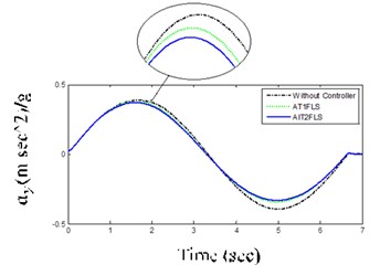
b) Body lateral acceleration for LC maneuver
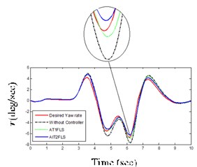
c) Yaw rate for DLC maneuver
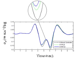
d) Body lateral acceleration for DLC maneuver
Fig. 12Proposed IT2FLS (solid), AT1FLS (dotted) in LC maneuver
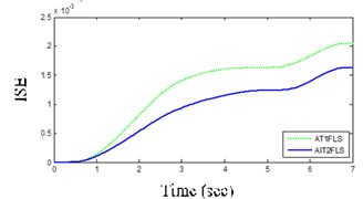
a) ISE
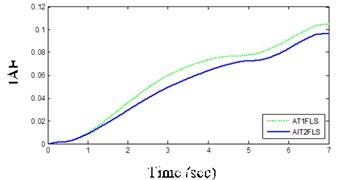
b) IAE
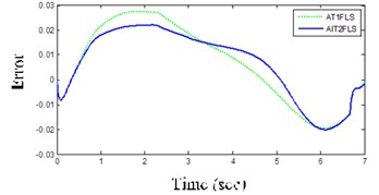
c) Error
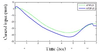
d) Control input signal
Fig. 13Proposed IT2FLS (solid), AT1FLS (dotted) in DLC maneuver
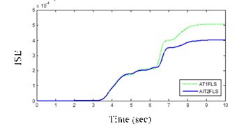
a) ISE
b) IAE
c) Error
d) Control input signal
6. Conclusions
This paper discusses the central importance of AIT2FLS versus AT1FLS in vehicle handling by a new nonlinear model of VGS as a vehicle active suspension system. The vehicle dynamics and characteristics of VGS are variable. Therefore, the variation of SMD should be decreased by an intelligent controller, and it must have soft responses in all the maneuvers. Two controllers including AT1FLS and AIT2FLS have been selected in this study. The results show that the highest handling can be provided by AIT2FLS where the yaw rate and body lateral acceleration are considered as the states of vehicle body. The important factors in the controllers are the ISE, IAE and maximum error. Note that all of these were very small for two types of maneuvers in AIT2FLS. As an important finding, the results revealed that AIT2FLS give soft responses during the process. The results also elucidate that VGS equipped with AIT2FLS could be a decent mechanism for the industrial researchers who worked in the field of vehicle active suspensions.
References
-
Wang L.-X. Stable adaptive fuzzy control of nonlinear systems. IEEE Transactions on Fuzzy Systems, Vol. 11, Issue 2, 1993, p. 146-155.
-
Wang L.-X. Stable adaptive fuzzy controllers with application to inverted pendulum tracking. IEEE Transactions on Fuzzy Systems, Vol. 26, Issue 5, 1996, p. 677-691.
-
Tang Y. Adaptive robust fuzzy control for output tracking. IEEE, American Control Conference, 2004.
-
Shahnazi R., Akbarzadeh-T. M.-R. PI adaptive fuzzy control with large and fast disturbance rejection for a class of uncertain nonlinear systems. IEEE Transactions on Fuzzy Systems, Vol. 16, Issue 1, 2008, p. 187-197.
-
Wai R.-J. Fuzzy sliding-mode control using adaptive tuning technique. Industrial Electronics, IEEE Transactions on Fuzzy Systems, Vol. 54, Issue 1, 2007, p. 586-594.
-
Wang C.-H., Cheng C.-S., Lee T.-T. Dynamical optimal training for interval type-2 fuzzy neural network (T2FNN). Systems, Man, and Cybernetics, Part B: Cybernetics, IEEE Transactions on Fuzzy Systems, Vol. 34, Issue 3, 2004, p. 1462-1477.
-
Li T.-S., Tong S.-C., Feng G. A novel robust adaptive-fuzzy-tracking control for a class of nonlinearmulti-input/multi-output systems. IEEE Transactions on Fuzzy Systems, Vol. 18, Issue 1, 2010, p. 150-160.
-
Lin T.-C., Chen M.-C., Roopaei M., Sahraei B. R. Adaptive type-2 fuzzy sliding mode control for chaos synchronization of uncertain chaotic systems. IEEE International Conference on Fuzzy Systems, 2010, p. 1-8.
-
Li H., Sun X., Shi P., Lam H.-K. Control design of interval type-2 fuzzy systems with actuator fault: sampled-data control approach. Information Sciences, Vol. 30, Issue 2, 2015, p. 1-13.
-
Ghaemi M., Hosseini-Sani S. K., Khooban M. H. Direct adaptive general type-2 fuzzy control for a class of uncertain non-linear systems. Science, Measurement and Technology, IET, Vol. 8, Issue 6, 2014, p. 518-527.
-
Lin T.-C. Based on interval type-2 fuzzy-neural network direct adaptive sliding mode control for SISO nonlinear systems. Communications in Nonlinear Science and Numerical Simulation, Vol. 15, Issue 12, 2010, p. 4084-4099.
-
Rajamani R. Vehicle Dynamics and Control. Springer, New York, 2011, p. 15-23.
-
Sharp R. Variable geometry active suspension for cars. Computing and Control Engineering Journal, Vol. 9, Issue 5, 1998, p. 217-222.
-
Sharp, R. Variable geometry active rear suspension for motorcycles. Proceedings of AVEC, Vol. 5, 2000, p. 22-24.
-
Watanabe Y., Sharp R. Mechanical and control design of a variable geometry active suspension system. Vehicle System Dynamics, Vol. 32, Issues 2-3, 1999, p. 217-235.
-
Lee S., Lee U., Han C.-S. Enhancement of vehicle handling characteristics by suspension kinematic control. Proceedings of the Institution of Mechanical Engineers, Part D: Journal of Automobile Engineering, Vol. 215, Issue 2, 2001, p. 197-216.
-
Lee S., Sung H., Kim J., Lee U. Enhancement of vehicle stability by active geometry control suspension system. International Journal of Automotive Technology, Vol. 7, Issue 3, 2006, p. 293-297.
-
Karpik G. J., Karpik D. J., Miers S. A., Lehman M. A. Vehicle Suspension System with Variable Geometry. United States Patent US 6,032,752, 2000.
-
Kim J.-W. Control Lever Structure of Active Geometry Control Suspension for Vehicles. Google Patents, United States Patent Application US 11/302,079, 2005.
-
Boston R. Vehicle Suspension System with a Variable Camber System. United States Patent US 7,914,020, 2011.
-
Lee U. K. Active Geometry Control Suspension System and Actuating Device Driving the Same. United States Patent US 8,226,091, 2012.
-
Lee U. K., Lee S. H., Choi H. R., Jang S. B., Kang B. G. Active Geometry Control Suspension. United States Patent US 8,226,091, 2012.
-
Evers W.-J., Besselink I., van der Knaap A., Nijmeijer H. Analysis of a variable geometry active suspension. International of Symposium on Advanced Vehicle Control, 2008, p. 350-355.
-
Goodarzi A., Oloomi E., Esmailzadeh E. Design and analysis of an intelligent controller for active geometry suspension systems. Vehicle System Dynamics, Vol. 49, Issues 1-2, 2011, p. 333-359.
-
Nemeth B., Gaspar P. Enhancement of vehicle stability based on variable geometry suspension and robust LPV control. Advanced Intelligent Mechatronics (AIM), IEEE/ASME International Conference, 2011, p. 253-258.
-
Baghaeian M., Akbari A. A. Enhancement of stability by adaptive fuzzy and active geometry suspension system. International Journal of Automotive Engineering, Vol. 3, Issue 3, 2013, p. 457-473.
-
Nemeth B., Gaspar P. Control design of variable-geometry suspension considering the construction system. IEEE Transactions on Vehicular Technology, Vol. 62, Issue 8, 2013, p. 4104-4109.
-
Gaspar P. Set-based analysis of the variable-geometry suspension system. World Congress, 2014, p. 11201-11206.
-
Zirkohi M. M., Lin T.-C. Interval type-2 fuzzy-neural network indirect adaptive sliding mode control for an active suspension system. Nonlinear Dynamics, Vol. 79, Issue 1, 2015, p. 513-526.
-
Tan D. W. W. T. A simplified type-2 fuzzy logic controller for real-time control. ISA Transactions, Vol. 45, Issue 4, 2006, p. 503-516.
-
Hsiao M.-Y., Li T.-H. S., Lee J.-Z., Chao C.-H., Tsai S.-H. Design of interval type-2 fuzzy sliding-mode controller. Information Sciences, Vol. 178, Issue 6, 2008, p. 1696-1716.
-
Karnik N. N., Mendel J. M. Type-2 fuzzy logic systems: type-reduction. IEEE International Conference on Systems, Man, and Cybernetics, , 1998, p. 2046-2051
-
Liang Q., Mendel J. M. Interval type-2 fuzzy logic systems: theory and design. IEEE Transactions on Fuzzy Systems, Vol. 8, Issue 5, 2000, p. 535-550.
-
Karnik N. N., Mendel J. M., Liang Q. Type-2 fuzzy logic systems. IEEE Transactions on Fuzzy Systems, Vol. 7, Issue 6, 1999, p. 643-658.
-
Karnik N. N., Mendel J. M. Centroid of a type-2 fuzzy set. Information Sciences, Vol. 132, Issue 1, 2001, p. 195-220.
-
Lin T.-C., Liu H.-L., Kuo M.-J. Direct adaptive interval type-2 fuzzy control of multivariable nonlinear systems. Engineering Applications of Artificial Intelligence, Vol. 22, Issue 3, 2009, p. 420-430.
-
Reimpell J., Stoll H., Betzler J. The Automotive Chassis: Engineering Principles. Second Edition, Butterworth-Heinemann, London, 2001, p. 160-175.
-
Wang L.-X. A Course in Fuzzy Systems. Prentice-Hall Press, New York, 1999, p. 118-127.

