Abstract
Reduction of cogging force is one of the main concerns of tubular permanent magnet linear motor (TPMLM). In this paper, an analytical calculation of air-gap magnetic density is derived. In addition, an analytical calculation of cogging force is deduced by the energy method. The impact of slots with different sizes on the Fourier coefficients of relative air-gap permanence function is demonstrated. When the nz/4p is the integer, it will produce the cogging force. Therefore, it is practical to reduce the cogging force by changing the Fourier coefficient smaller. The effectiveness of the theoretical analysis is validated by experimental results.
1. Introduction
With dramatic view of permanent magnet materials, the tubular permanent magnet linear motor (TPMLM) have made great improvement. They have been applied in different types of high control precision and positioning accuracy system. However, the performance of the TPMLM can be further enhanced by analysis and appropriate design of the internal structure. Hence, the enhancement of the performance of TPMLM deserves in-depth research.
The stator has side slots which can improve the performance of TPMLM. However, it may make the waveform of magnetic field distorted and change the energy of magnetic field according to its location. The force is volatile due to the cogging force. The volatility characteristics will impact the control accuracy of system. The force is important to maintain TPMLM. In the system, the size and volatility are the most important factors of the force. The size of force is dependent on the size of winding currents, which are not the main focus and are not illustrated in this paper. The volatility of force depends on the size of cogging force, i.e. the cogging force can be crippled by decreasing the volatility. The factors influencing the cogging force and the methods used to reduce have been demonstrated in previous literature [1-13]. Analytical solutions to investigate the coefficient, skewed slots, shape of magnetic pole which can influence the electromagnetic torque were studied to make magnet rotating motor permanent [1-8]. In [9-12], the coefficient affecting electromagnetic force and the methods to reduce the cogging force were demonstrated to improve the performance of TPMLM. In this paper, a new method to reduce the cogging force with different sizes of slots in a permanent magnet rotating motor rather than in a TPMLM is proposed. In addition, an analytical calculation of cogging force and the expressions of Gn under different sides of slots are derived.
2. TPMLM Magnetic Field Estimation
In this paper, every drop total magnetic pole in the TPMLM magnetic circuit is denoted as F and every drop air gap magnetic pole is denoted as Fδ, hence we have:
where ks is the magnetic circuit saturation coefficient; δ is the air gap length effectively; Hδ is the air gap magnetic field.
According to the Ohms law of magnetic circuit, the closed magnetic circuit by the permanent magnet and external magnetic circuit satisfy with the following relationship:
where hm is the width of permanent magnet; H and Φm are the magnetic field intensity and flux magnetic flow of PM; σ is the magnetic leakage factor; Φδ is the air gap flux.
Combing Eq. (1) and Eq. (2), yields:
When the demagnetizing curve of PM is a straight line, yields:
where μ0 is the air gap permanence; μr is the relative magnetic permeability of PM; Br is the remnant magnetism of PM.
Considering the existence of leakage flux, we have:
Combining Eqs. (3), (4) and (5), we have:
When the saturation of PM, leakage flux, and cogging effect are ignored, yields:
3. Cogging force analytical research of TPMLM
In [14], the cogging torque of the permanent magnet rotating motor was the magnetic energy W with respect to the position angle α. The TPMLM could be considered similar to the PM rotating motor, that is:
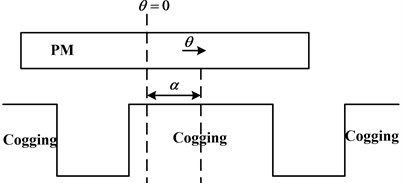
where α is the angle between the camber line of cogging and PM and is corresponding to the cogging. It is also the relative location of stator and motor. In Fig. 1, the camber line of the PM is θ= 0.
The energy of a motor can be similarly considered in the air-gap and PM, that is:
In (8), W depends on the motor structural parameters, performance of PM, and the relative position of stator and motor.
In Eq. (6):
Substitute Eq. (9) into Eq. (8), yields:
Fig. 1Relative location of PM and stator
3.1. The Fourier expression of B2r(θ)
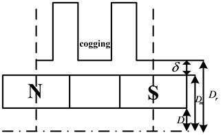
When the PM in TPMLM has a uniform distribution, the distribution map of Br(θ) can be illustrated as shown in Fig. 2. The Fourier expansion of B2r(θ) can be expressed as:
where Br0=αpB2r, Brn=2nπB2rsinnαpπ; p is the number of pole-pairs; Br is the remnant magnetism of PM; αP is the coefficient of PM.
Fig. 2Distribution map of Brθ

3.2. Fourier expression of [hm(θ)hm(θ)+δ(θ,α)]2
where z is the number of slots of TPMLM.
TPMLM is evolved by the rotating permanent magnet motor. Hence, the motor may move with displacement x, which is equivalent to the deflection angle of the rotating permanent magnet motor:
where C is the actual length of stator when it is 2π.
Fig. 3 presents a simulation model to calculate the energy of TPMLM in one pole.
Fig. 3Model for calculating TPMLM’s energy in one pole
Substitute Eqs. (11)-(13) into (10), yields:
⇒∂W∂α=π2zD4μ0(Cπδ+δ2)∑∞n=1GnBr(nz2p)sin(nzα),
where δ is the air-gap size; D is radius axis of the motor; z is the number of slots; p is the pole pairs.
Combining (13) and (14), the cogging force can be derived as:
In (15), Gn and Br have a significant impact on the cogging force. However, not all integer n can produce the cogging force, only n can make nz/2p to produce the integer. Hence, it is possible to investigate the rules of cogging force by the greatest common divisor of z and 2p. The varying rule of cogging force is periodical, and its cycles are dependent on the number of poles and slots of TPMLM, that is:
where Np is the cycles of cogging force; GCD(z,2p) is the greatest common divisor.
4. Research for reducing cogging force by slots with different sizes
4.1. Expression of cogging force in different sizes of slots
In Eq. (6) the magnetic flux density is dependent on the size of the air-gap. When the sizes of slots are different, Fourier decomposition of B2r(θ) becomes invariable. However, [hm/hm+δ(x,y)]2 is variable due to the fact that the sizes of adjacent slots are different. Hence, the cogging force can be weakened by changing the Fourier coefficient of [hm/hm+δ(x,y)]2.
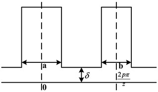
Fig. 4 is a schematic diagram of stator with different sizes of slots. In Fig. 4, the length of a and b illustrates the size of adjacent slots. Fourier decomposition of [hm/hm+δ(x,y)]2 is in the area of [-2pπ/z,2pπ/z]. The expression of Fourier decomposition can be obtained as:
Fig. 4Sizes of slots in stator
Assuming that the magnetic line is only passing through the cogging of stator, the air-gap length of cogging is δ(x)=δ and the slot is δ(x)=∞. At that time, [hm/hm+δ(x,y)]2 in the slot part is zero, while the cogging part is [hm/hm+δ]2. Hence, when the sizes of slots are different, the expression of Gn can be written as:
Thus, the expression of cogging force can be written as:
where n is the size which can adjust nz/4p to an integer.
From Eqs. (18) and (19), one can get that: the Fourier coefficient of [hm/hm+δ(x,y)]2 has a significant impact on the cogging force. However, the Fourier coefficient cannot produce the cogging force, only the Fourier coefficient of n can vary nz/4p to an integer and produce the effect. Hence, the cogging force can be weakened as long as the corresponding measurement to make the Fourier coefficient which can produce the cogging force being smaller.
4.2. Selection principle of different sizes of slots
The sizes of Gn can be distinguished by their width to determine whether it is different or not.
When the sizes of slots are equal:
When n is odd:
When n is even:
The sizes of slots are different.
When n is odd:
When n is even:
Hence, when the n is odd, Gn in different slots is consistently larger than in the equal slots, which indicates that different slots cannot weaken the cogging force. However, when the n is even, it can vary the sizes of a and b to make Gn zero to meet the weaken of cogging force requirement. From Eqs. (24):
where LCM (z,4p) is the least common multiple z and 4p. To make Gn zero, the following relationship needs to be satisfied:
The size of a and b can be obtained as:
Fig. 5Cogging force contrast with slots which have same and different sizes
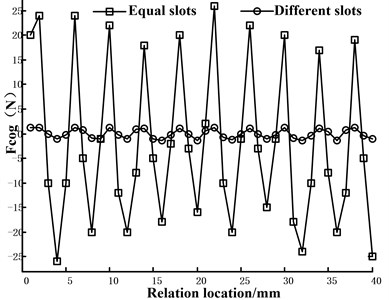
Take the TPMLM which has ten poles and nine slots to validate the effectiveness of whether using different slots can weaken the cogging force. In this TPMLM, n=4p/GCD(z,4p). It can produce the cogging force and is an odd number. Hence, different slots can be used to reduce the cogging force.
From Eqs. (25), it can be derived that a=τp/15, b=τp/45. Fig. 5 illustrates the cogging force contrast with the slots which have the same and different sizes. In Fig. 5, the slots have reasonable sizes and can make Gn equal to zero and the cogging force changes from 25 N to 1.5 N. The size of cogging is weakened significantly.
Then the motor simulation model with different slots is analyzed in ANSYS, the results are shown in Fig. 6.
It can effectively reduce the thrust ripple of the motor, and then reduce the noise of the motor.
Fig. 6Modal analysis of stator core
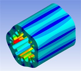
a) 8317 Hz
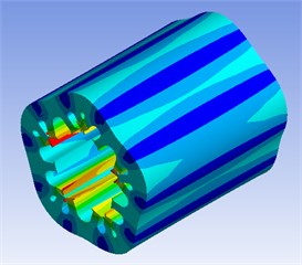
b) 8431 Hz
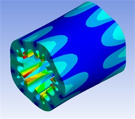
c) 9542 Hz
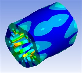
d) 9553 Hz
5. Experiment research
To validate the method for reducing the cogging force by slots with different sizes, a prototype of ten-poles and nine-slots motor is selected in the experiment. The basic parameters of TPMLM are listed in Table 1. The experiment platform includes a prototype motor, control circuits, and test circuits. Fig.7 shows a photo of the experiment platform.
Table 1Basic parameters
Parameters | Value (mm) | Parameters | Value (mm) |
Stainless steel shaft | 15 | Pole | 10 |
Rotor outer diameter | 30 | Slot | 9 |
Size of air-gap | 1.5 | Material of stator | Silicon steel |
Stator outer diameter | 48 | Magnetization direction | Axially |
Polar distance | 18 | Material of PM | NdFeB |
The force of the prototype motor is tested to validate the effectiveness of analytical results. The force measuring principle is presented in Fig. 8.
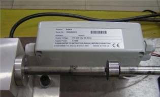
In Fig. 8, the cogging force (Fcog) is equal to the value of load cells (F). By changing the axle position of TPMLM, different values of cogging force can be obtained. The thrust force sensor and modulator are shown in Fig. 9.
Fig. 7Experimental platform
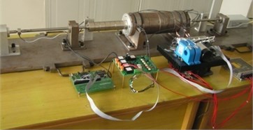
Fig. 8Sketch map of force measuring principle
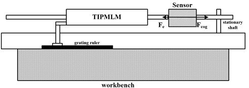
Fig. 9Thrust force sensor and modulator
When a is τp/15 and b is τp/45, force of the prototype ten-poles and nine-slots motor is tested. The forces in each point can be obtained by the static displacement method. The cogging force can be attained by subtracting the average thrust from the former obtained forces. The comparison of TPMLM cogging force between the experimental and analytical methods with two auxiliary slots is shown in Fig. 10.
Fig. 10Cogging force of TPMLM with two auxiliary slots comparisons
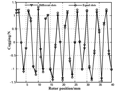
In Fig. 10, the cogging force of TPMLM with two auxiliary slots in which the reaction was calculated and the results were consistent with the experimental data. In Fig. 5, the cogging force of TPMLM with different slots was remarkably weakened in equal slots. Therefore, the validity of the solution is verified by the results.
The motor vibration can be used to justify the improvement of the performance. Hence, a motor vibration experiment is designed. The vibration measurement has seven measuring points in the Fig. 11. The accelerated speed of vibration is taken to indicate the motor drumming noise. The vibration measurer and accelerated speed sensor (in the Fig. 12 and Fig. 13) are used to test the performance. The accelerated speed of vibration to TPMLM are listed in the Table 2. It can be seen that the motor drumming noise has become smaller.
Fig. 11Scheme of points for measuring motor vibration

Fig. 12ECON6008vibration measurer
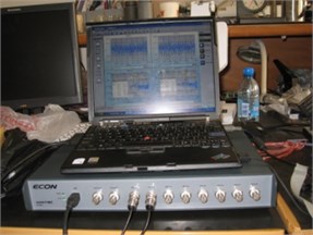
Fig. 13Accelerated speed sensor
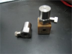
Table 2Accelerated speed of vibration
Measuring points | Equal slots (m2/s) | Different slots (m2/s) |
1 | 4.02 | 3.76 |
2 | 0.61 | 0.55 |
3 | 0.51 | 0.5 |
4 | 0.58 | 0.54 |
5 | 0.46 | 0.42 |
6 | 0.56 | 0.51 |
7 | 3.88 | 3.25 |
6. Conclusions
In this paper, an analytical calculation of air-gap magnetic density has been demonstrated and an analytical calculation of cogging force has been derived by the energy method. The expression of Gn have been elicited by the formula of cogging force, which can obtain the selection law of different sizes of slots. When n is odd, Gn in the different slots is consistently larger than that in the equal slots. Therefore, different slots method cannot be used to reduce the cogging force. However, when n is even, it can change the sizes of a and b to make the Gn zero to meet the weaken of cogging force requirement. Finally, taking the prototype ten poles and nine slots motor to experiment, the cogging force was remarkably weakened and the conclusions have been validated by experimental analysis.
References
-
Wang Xiuhe, Yang Yubo, Fu Dajin Study of cogging torque in surface-mounted permanent magnet motors with energy method. Journal of Magnetism and Magnetic Material, Vol. 267, Issue 1, 2003, p. 80-85.
-
Xu Yuetong, Fu Jianzhong, Chen Zichen Thrust ripple optimization and experiment for PMLSM. Proceedings of the CSEE, Vol. 25, Issue 12, 2005, p. 122-126.
-
Hwang C. C., John S. B., Wu S. S. Reduction of cogging torque in spindle motors for CD-ROM drive. IEEE Transactions on Magnetics, Vol. 34, Issue 2, 1998, p. 468-470.
-
Zhu Z. Q., Howe D. Influence of design parameters on cogging torque in permanent magnet machine. IEEE Transactions on Energy Conversion, Vol. 15, Issue 4, 2000, p. 407-417.
-
Lukaniszyn M., Jagiela M., Wrobel R. Optimization of permanent magnet shape for minimum cogging torque using genetic algorithm. IEEE Transactions on Magnetics, Vol. 40, Issue 2, 2004, p. 1228-1231.
-
Lee Man Gi, Lee Seung Hwan, Park Byung Ho, et al. Optimized design to improve the function of a magnetic pulse forming device. Journal of Vibroengineering, Vol. 17, Issue 7, 2015, p. 3998-4010.
-
Wang Daohan, Wang Xiuhe, Zhang Ran, et al. Novel method for reducing cogging torque in surface-mounted permanent magnet motor with different width of permanent magnets. Electric Machines and Control, Vol. 12, Issue 4, 2008, p. 380-384.
-
Yang Yubo, Wang Xiuhe Effect of permanent magnet asymmetry on cogging torque of interior permanent magnet motor. Electric Machines and Control, Vol. 14, Issue 12, 2010, p. 58-62.
-
Quan Lei, Fan Chengzhi, Ye Yunyue Cogging force reduction method by optimization of pole arc in permanent magnet linear motors. Journal of Mechanical and Electrical Engineering, Vol. 28, Issue 10, 2011, p. 1209-1212.
-
Jiabin Wang, Weiya Wang, Kais Atallah Linear permanent magnet motor for active vehicle suspension. IEEE Transactions on Vehicular Technology, Vol. 60, Issue 1, 2011, p. 55-63.
-
Bianchi N., Bolognani S. Design techniques for reducing cogging torque in surface-mounted PM motors. IEEE Transactions on Industry Applications, Vol. 85, Issue 5, 2002, p. 1259-1265.
-
LI Liyi, Huang Xuzhen, Pan Donghua Magnetic field of tubular linear motor with special permanent magnet. IEEE Transactions on Plasma Science, Vol. 39, Issue 1, 2011, p. 83-86.
-
Huang Kefeng, Li Huaishu, Zhou Yu Method research for cogging force reduction by auxiliary slots. Electric Machines and Control, Vol. 18, Issue 3, 2014, p. 54-59.
About this article
Pengfei Hou conceived the study that led to the submission, acquired data, and played an important role in interpreting the results. Kefeng Huang performed the experiments and analyzed the data. Puyu Wang reviewed and edited the manuscript. Jinquan Wang revised the article critically for important content. Ye Xu helped perform the analysis with constructive discussions.

