Abstract
Under major earthquakes, high-rise steel moment frames designed according to the current codes will experience an inelastic deformation, which is difficult to predict and control. According to the principle of work-energy balance, a performance-based plastic design (PBPD) methodology is put forward for the design of high-rise steel frames in this study. In this method, the target drift and yield mechanisms are pre-selected as key performance criteria. The design base shear in a given earthquake level is calculated based on the work-energy balance principle that the work required to push the structure monotonically to the target drift is equal to the energy needed by an equivalent single degree of freedom to reach the same state. The plastic design is utilized to design the frame components and connections so as to attain the desired yield mechanism and behavior. The method has been adopted to design a ten-story steel moment resisting frame, and has been validated by nonlinear dynamic time history analyses and pushover analysis. The results indicate that the frames develop targeted strong column sway mechanisms, and the story drifts are less than the target values, thus satisfying the anticipated performance objectives. The addressed method herein can form a basis for the performance-based plastic design of high-rise steel moment resisting frames.
1. Introduction
The steel moment frames designed according to the current codes will be subjected to an inelastic deformation under major earthquakes. However, the current seismic design code is generally based on the elastic behavior and considers the inelastic behavior indirectly. In the current China’s seismic design code, it is a practice to calculate the design base shear and elastic drift from code-specified elastic acceleration response spectrum during the minor earthquake, then design members for different combinations of internal forces, and check the elastic drift. The inelastic drift under major earthquakes is estimated as the elastic drift multiplied by a drift amplification factor and should not be beyond the specified limits. To ensure the expected ductility demands and energy dissipation capacity, some appropriate detailing measures should be taken. When hit by the strong earthquakes, however, the structures designed by the above methods will suffer inelastic deformations, which is very difficult to predict and control [1-9]. The inelastic behavior may include severe yielding and buckling of structural members and connections. These inelastic behaviors may be unevenly distributed in the structure, which may lead to a rather unfavorable response, sometimes even total collapse, or laborious and expensive repair work [10-12].
In recent years, it is found that quite a few strong earthquakes have led to great loss of life and property. The strength-based seismic design method cannot satisfy the requirements, and furthermore the performance-based seismic design (PBSD) method has been in the limelight. The performance-based seismic design philosophy has emerged as a promising and efficient seismic design approach. PBSD explicitly accounts for the inelastic behavior of a structural system in the design process itself [13-17]. However, the PBSD method depends primarily on an iteration process, namely, “Evaluate performance”, “Modify design”, “Evaluate performance” until the designed structure can reach the desired performance [10-12]. A recently developed performance-based plastic design (PBPD) methodology is considered in the present study in which inelastic characteristics of structural components are directly considered in the design [18, 19]. This design methodology has already been successfully applied to various structural systems [10, 20-25]. This study presents an application of PBPD method to high-rise steel moment frames. A steel moment resisting frame has been designed using the PBPD method in accordance with GB50011-2010 Code [1]. In this method, the target drift and yield mechanisms are pre-selected as key performance criteria. The design base shear in a given earthquake level is calculated based on the work-energy balance principle that the work required to push the structure monotonically to the target drift is equal to the energy needed by an equivalent single degree of freedom to reach the same state. The plastic design is utilized to design the frame members and connections so as to attain the desired yield mechanism and behavior. The PBPD method can account for the inelastic structural behavior directly without any evaluation and iteration. The concept of the PBPD method is very clear and the design process is simple, which can enjoy a wide engineering application.
2. PBPD method
The PBPD method employs pre-selected target drift and yield mechanisms as performance limit states. These two limit states are directly dependent on the degree and distribution of structural damages, respectively. The design base shear for a specified earthquake level, is calculated based on the work-energy balance principle that the work required to push the structure monotonically to the target drift is equal to the energy needed by an equivalent EP-SDOF to reach the same state (Fig. 1). Then the plastic design is utilized to design the frame members and connections so as to attain the desired yield mechanism and behavior.
Fig. 1PBPD concept
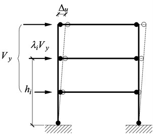
a) Yield mechanism
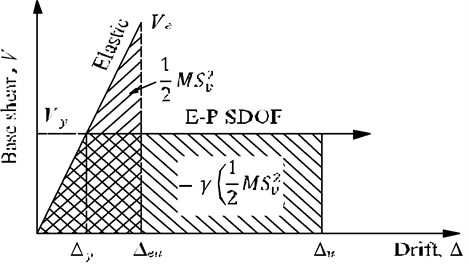
b) Energy-work balance concept
2.1. Design base shear
For a given earthquake level it is primary to determine the design base shear in the PBPD method. It is calculated based on the work-energy balance principle that the work required to push the structure monotonically to the target drift is equal to the energy needed by an equivalent EP-SDOF system to reach the same state. Assuming the system is an idealized elasto-plastic system, the work-energy equation is as following:
where and are the elastic and plastic components of the energy (work) required to displace the structure to the objective drift; is the design spectral velocity; is the design spectral acceleration; is the fundamental period of vibration; and is the total mass of the system; is the acceleration due to gravity; is the energy modification coefficient, which is dependent on the ductility coefficient of the structure and the ductility reduction coefficient . can be obtained according to the relation:
The elastic component can be given by the following:
where is the total weight of the system, is the yield base shear.
The plastic energy term is equal to the energy dissipated by the plastic hinges occurring in the structure, as shown in Fig. 1. For a given yield mechanism, the plastic energy also equal to the external work done by the design lateral forces can be obtained by:
where is the global inelastic drift ratio of the structure see (Fig. 1), which is the difference between the pre-selected design drift ratio and yield drift ratio .
According to Eqs. (1), (3) and (4), the work-energy equation can be re-written in the following form:
or:
The admissible solution of Eq. (6) gives the required design base shear coefficient:
where is a dimensionless parameter given by:
and .
2.2. Lateral force distribution
It is well known that building structures designed according to current code are expected to undergo large deformations when subjected to major earthquakes. Therefore, the vertical distribution of design lateral forces along the building height is supposed to reflect the actual distribution of story shear under major earthquakes. However, the equivalent static design lateral forces in the current codes are obtained from simplified models assuming that the structures behave elastically and primarily in the first mode of vibration. For the PBPD method, the lateral force distribution cannot be utilized until the distribution is based on nonlinear dynamic analyses and is verified.
On the basis of nonlinear time history analyses, Lee [26] proposed a new design lateral force distribution. Analytical results have shown that: 1) Frames designed by using this lateral force distribution experienced more uniform maximum interstory drifts along the height than the frames designed by using current code distributions; 2) This force distribution also gives a very good estimate of maximum column moment demands when the structures are responding to severe ground motions and deform into the inelastic range; 3) Higher mode effects are well reflected in the proposed design lateral force distribution. Soon-Sik Lee adopted a new concept of shear distribution factor, which is the ratio of the story shear force at story to that at the top story. This shear distribution factor is expressed as:
where, and respectively are the weight of structure at story and at the top th story. and are the height of story and from the base. The exponent is a numerical factor to be determined.
Using Eq. (9), the story shears at story and at the top story can be written as:
The shear distribution factor plays and important role in the performance-based plastic design procedure. The factor is directly related to the story lateral strength and stiffness along the height of the structure. It also represents the variation of story drifts along the height, indirectly.
According to the research achievements [26], the parameter can be taken as follows:
Consequently, the story shear at the top story and shear distribution factor are respectively:
The lateral force applied at story can be given as:
or:
where, is the story distribution factor at story 1, and .
2.3. Member design in steel frames
2.3.1. Design of beams (designated yielding members)
During the major earthquakes, in order to avoid structural collapse, dissipate the input energy maximally, and ensure the sufficient strength and ductility of structure, it is necessary to select a reasonable yield mechanism at the beginning of design. When the target yield mechanism shown in Fig. 2 is adopted for steel moment frames, it is natural that the beams become the primary designated yielding members (DYM). The required moment capacity of beams at each story can be yielded by the plastic design approach and referring to Fig. 2:
where is the required moment strengths of beams at story . The rotation term (Fig. 2). Note that the external work done by the uniform gravity load is zero since the beams experience the antisymmetric deformations.
The relevant research results have indicated that the desirable distribution of structural strength along the building height should correspond to the distribution of the design story shears. This contributes to the more uniform distribution of the yielding along the height, thus to avoid the concentrated yielding at a few stories. That is:
where is the required plastic moment of beams at the top story.
Fig. 2Target yield mechanism for moment frames
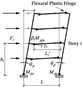
Fig. 3Single span moment frame with a soft story
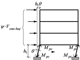
During the earthquake, in order to prevent the soft story mechanism occurring in the first story (shown in Fig. 3), the required plastic moment of columns should be reasonably determined. Assuming that plastic hinges arise at both ends of the first story columns, for a small deformation , the corresponding work equationis [26]:
then:
where, is a small mechanism deformation, is the base shear (for an equivalent one bay model), which may be taken as divided by the number of bays; is the height of the first story; the factor accounts for over strength above the design force. This method was used in the design example with a value of 1.1 for the over strength factor .
Substituting Eqs. (20) and (18) into Eq. (17), the required plastic moment of beams at story can be obtained.
The steel beams can be designed according to flexural members, and the cross section of the beam at story should satisfy the following:
where, is the design plastic moment of beams at story , is the plastic net section modulus of beams.
2.4. Design of columns (non-DYM)
Columns are non-designated yielding members (non-DYM) and they must have enough strength to resist the unfavorable combinations of factored gravity loads and maximum expected strength of the DYM simultaneously by involving the consideration of reasonable strain-hardening and over strength of materials. In the design of moment frames, the steel columns can be separated as cantilever free bodies. The free-body diagram of an exterior column at the target drift is shown in Fig. 4.
Fig. 4Free-body diagram of an exterior column
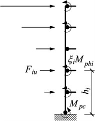
In order to guarantee that the intended strong column-weak beam mechanism will accrue to the structure; the designed columns must resist the maximum expected forces by considering a reasonable extent of strain-hardening and material over strength in the beam plastic hinges. The moment of plastic hinge at a strain-hardened beam can be determined by multiplying the required moment strengths by an appropriate overstrength factor , which should account for the effect of strain-hardening and material over strength. Assuming the distribution of the required lateral forces acting on this free body may follow the distribution as given by Eq. (16), the magnitudes of can be readily obtained by the equilibrium conditions of the free body. Then the moments and shear force of column at each story can be computed by the use of the beam end moments and lateral forces applied at each story .
In the case of steel moment frames, the sum of required counterbalance lateral forces, , acted on the free body of an exterior column can be obtained as Fig. 5(a):
where is the width of shear plate and:
Eq. (22) neglects the gravity load on the short length of the beam between the plastic hinge and the face of the column.
For the case of interior column tree, both directions of lateral forces lead to the same result; hence only the lateral forces acting to the left are shown in Fig. 5(b).
The sum of lateral forces, , can be calculated as:
Fig. 5Free-body diagram of a column tree
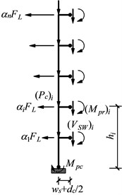
a) Free-body diagram of an exterior column tree (lateral forces acting to the left)
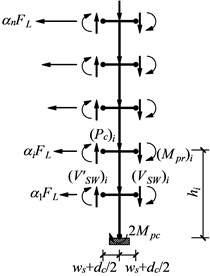
b) Free-body diagram of an interior column tree (lateral forces acting to the left)
3. PBPD procedure
(1) For the design earthquake level, select a desired yield mechanism and target drift for the structure consistent with the intended performance objectives. Assume idealized elastic-plastic (EP) force-displacement behavior and estimate yield drift ratio, , for the structure.
(2) Compute the plastic drift ratio by deducting the yield drift ratio from the pre-selected target drift ratio .
(3) Estimate fundamental period for the system from the mass and stiffness properties. Empirical formulae based on codes (e.g. GB50009-2012) can also be used to estimate the expected fundamental period of the system. Use an appropriate vertical distribution of design lateral forces.
(4) With the information in Steps 1 and 2, along with the design spectral acceleration value, , calculate the design base shear, , by the work-energy balance principle that the work required to push the structure monotonically to the target drift is equal to the energy needed by an equivalent single degree of freedom to reach the same drift. At this time, a rational theory of inelastic seismic response spectrum for EP-SDOF can be employed, such as idealized inelastic response spectra proposed by Newmark-Hall or other methods.
(5) If the force-deformation behavior of the structure is different from the assumed elasto-plastic behavior, then design base shear should be modified.
(6) Use the plastic method to design the beams (Designated Yielding Members, DYM), while having the distribution of lateral strength of the structure along the height follow the distribution of design story shear. Columns required to remain elastic (non-DYM), are designed by a capacity design approach, by accounting for the strain-hardening and material over strength of the DYM as well as by including the effects due to the frame deformation.
4. Case study
4.1. Project overview
The project is a ten-story steel frame with the story height of 3.6 m. The floor and roof dead loads are 4.5 kN/m2, the floor live load is 2.0 kN/m2, the roof live load is 0.5 kN/m2, and the snow load is 0.3 kN/m2. The seismic fortification intensity is 8°. The site condition is type Ⅱ. The design earthquake classification is the 1st group. The framing plan and elevation of the moment frame are shown in Figs. 6-7, respectively.
Fig. 6Floor plan of structure
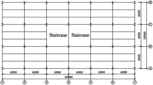
Fig. 7Elevation view of structure
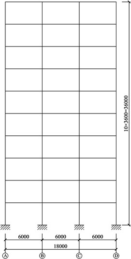
Table 1Member sections
Floor | Beam section | Exterior column section | Interior column section |
10 | H450×220×8×10 | H400×400×12×16 | H400×400×12×16 |
9 | H450×220×8×10 | H400×400×12×16 | H400×400×12×16 |
8 | H450×220×8×10 | H400×400×12×16 | H400×400×12×16 |
7 | H450×220×8×10 | H400×400×12×16 | H400×400×12×16 |
6 | H450×220×8×10 | H400×400×12×16 | H400×400×12×16 |
5 | H500×200×8×10 | H450×450×15×20 | H450×450×15×20 |
4 | H500×200×8×10 | H450×450×15×20 | H450×450×15×20 |
3 | H500×200×8×10 | H450×450×15×20 | H450×450×15×20 |
2 | H500×200×10×16 | H500×500×15×20 | H500×500×15×20 |
1 | H500×200×10×16 | H500×500×15×20 | H500×500×15×20 |
The welded H-shaped sections are selected for both beams and columns and the steel is Q235-B.F. The preliminary member sections are show in Table 1.
4.2. Design base shear and lateral force distribution
(1) Estimate fundamental period.
According to load code for the design of building structures [27], the fundamental period of the structure can be estimated as: , 0.15×10 s.
(2) Determine the yield drift ratio and target yield ratio.
The target yield mechanism is shown in Fig. 2. Assuming that beam plastic hinges is 0.54 m away from the column face.
According to the document [11], the yield drift ratio can be taken as 1 % for steel frames. The design base shear was determined in accordance with two performance objectives: 1) a maximum story drift ratio is 2 % for a ground motion hazard with 10 % probability of exceedance in 50 years (moderate earthquake); 2) a maximum story drift ratio is 3 % for a ground motion hazard with 2 % probability of exceedance in 50 years (Major earthquake).
(3) Determine the acceleration response spectrum.
According to Code for seismic design of buildings [1], the acceleration response spectrum can be obtained as:
where, is the maximum seismic coefficient, which can be specified from Code for seismic design of buildings [1].
Table 2Design parameters for PBPD frame
Design parameters | Moderate earthquake | Major earthquake |
0.121 g | 0.242 g | |
1.5 s | 1.5 s | |
Yield drift ratio | 1.0 % | 1.0 % |
Target drift ratio | 2.0 % | 3.0 % |
Inelastic drift ratio | 1.0 % | 2.0 % |
2.0 | 3.0 | |
2.0 | 3.0 | |
0.75 | 0.556 | |
0.976 | 1.951 | |
0.059 | 0.089 | |
Design base shear | 390 kN | 590 kN |
(4) Calculate design base shear.
On the basis of the above parameters, the design base shear can be calculated from Eq. (7). The calculated values of all significant design parameters are listed in Table 2.
(5) Calculate lateral force distribution.
The design lateral force distribution as calculated by using Eqs. (14) to (16) is shown in Table 3.
Table 3Lateral force distribution calculation for PBPD frame
Floor | (m) | (kN) | (kN·m) | (kN·m) | (kN) | (kN) | |||
10 | 36 | 565 | 20340 | 20340 | 1.000 | 1.000 | 36.000 | 164.47 | 164.47 |
9 | 32.4 | 670 | 21708 | 42048 | 1.652 | 0.652 | 21.138 | 107.30 | 271.77 |
8 | 28.8 | 670 | 19296 | 61344 | 2.146 | 0.493 | 14.205 | 81.12 | 352.89 |
7 | 25.2 | 670 | 16884 | 78228 | 2.539 | 0.393 | 9.901 | 64.62 | 417.51 |
6 | 21.6 | 670 | 14472 | 92700 | 2.855 | 0.316 | 6.830 | 52.00 | 469.52 |
5 | 18 | 670 | 12060 | 104760 | 3.107 | 0.252 | 4.535 | 41.44 | 510.96 |
4 | 14.4 | 670 | 9648 | 114408 | 3.302 | 0.195 | 2.810 | 32.10 | 543.05 |
3 | 10.8 | 670 | 7236 | 121644 | 3.445 | 0.143 | 1.545 | 23.53 | 566.58 |
2 | 7.2 | 670 | 4824 | 126468 | 3.539 | 0.094 | 0.676 | 15.45 | 582.03 |
1 | 3.6 | 691 | 2487.6 | 128955.6 | 3.587 | 0.048 | 0.173 | 7.89 | 589.92 |
∑ | 6616 | 128955.6 | 3.587 | 97.814 | 589.92 |
4.3. Design of beams
The distance of the plastic hinges from the face of the columns was assumed as 0.54 m. The plastic moment of the columns at the base in one-bay model was calculated by using the modified Eq. (20):
The required beam strength at each floor story was calculated by using Eqs. (17) and (18). The design parameters for the beams are given in Table 4.
Table 4Design parameters for beams
Floor | (kN) | (kN·m) | (kN·m) | Required plastic modulus | Design section | Plastic modulus |
10 | 54.82 | 1973.63 | 77.56 | 330023.8 | H250×120×8×12 | 444782 |
9 | 35.77 | 1158.87 | 128.15 | 545338.4 | H280×140×8×12 | 581312 |
8 | 27.04 | 778.76 | 166.41 | 708115.1 | H320×150×8×12 | 729632 |
7 | 21.54 | 542.79 | 196.88 | 837776.1 | H350×160×8×12 | 861512 |
6 | 17.33 | 374.43 | 221.40 | 942127.3 | H370×170×8×12 | 969752 |
5 | 13.81 | 248.64 | 240.94 | 1025282 | H380×180×8×12 | 1048352 |
4 | 10.70 | 154.08 | 256.08 | 1089692 | H380×190×8×12 | 1092512 |
3 | 7.84 | 84.70 | 267.17 | 1136904 | H400×190×8×12 | 1167392 |
2 | 5.15 | 37.07 | 274.46 | 1167897 | H400×200×8×12 | 1213952 |
1 | 2.63 | 9.47 | 278.18 | 1183736 | H400×200×8×12 | 1213952 |
4.4. Design of columns
The design of columns was done by using the concept of column tree. The column trees for the 4-story frame were shown in Fig. 5, where the terms , , and treated as applied loads. Similar column trees were constructed for this 10-story frame as well. The sum of required balancing lateral forces for the exterior and interior column trees were obtained by using Eqs. (22) and (24), respectively. For the exterior column tree came out as 115.14 kN and that for the interior column tree as 183.08 kN. Design parameters for the columns are listed in Table 5, and Table 6 gives the required strength of the columns. Final column sections are shown in Table 7.
Table 5Design parameters for columns
Floor | Exterior column | Interior column | |||||
(kN) | Column shear (kN) | (kN) | Column shear (kN) | ||||
10 | 77.56 | 0.28 | 10.04 | 32.18 | 32.18 | 57.11 | 57.11 |
9 | 134.56 | 0.18 | 5.89 | 21.00 | 53.18 | 37.26 | 94.37 |
8 | 174.73 | 0.14 | 3.96 | 15.87 | 69.05 | 28.17 | 122.54 |
7 | 206.72 | 0.11 | 2.76 | 12.64 | 81.69 | 22.44 | 144.98 |
6 | 232.47 | 0.09 | 1.90 | 10.18 | 91.87 | 18.06 | 163.04 |
5 | 252.99 | 0.07 | 1.26 | 8.11 | 99.97 | 14.39 | 177.43 |
4 | 268.88 | 0.05 | 0.78 | 6.28 | 106.25 | 11.15 | 188.57 |
3 | 280.53 | 0.04 | 0.43 | 4.60 | 110.86 | 8.17 | 196.74 |
2 | 288.18 | 0.03 | 0.19 | 3.02 | 113.88 | 5.36 | 202.11 |
1 | 292.09 | 0.01 | 0.05 | 1.54 | 115.43 | 2.74 | 204.85 |
∑ | 1.00 | 27.27 | 115.43 | 204.85 | |||
Table 6Required strength for columns of PBPD frame
Floor | Exterior column | Interior column | ||
Moment (kN·m) | Axial force (kN) | Moment (kN·m) | Axial force (kN) | |
10 | 118.44 | 126.23 | 182.49 | 181.26 |
9 | 197.26 | 305.40 | 293.51 | 423.72 |
8 | 247.76 | 500.33 | 364.89 | 666.18 |
7 | 278.76 | 707.81 | 410.13 | 908.64 |
6 | 294.53 | 925.38 | 435.19 | 1151.10 |
5 | 297.82 | 1151.00 | 443.51 | 1393.56 |
4 | 290.61 | 1382.85 | 437.43 | 1636.02 |
3 | 274.49 | 1619.27 | 418.62 | 1878.48 |
2 | 250.80 | 1858.69 | 388.40 | 2120.94 |
1 | 220.83 | 2099.64 | 348.07 | 2363.40 |
Column base | –194.7 | –389.4 | ||
Table 7Member sections for PBPD frame
Floor | Beam | Exterior column | Interior column |
10 | H250×120×8×12 | H250×250×10×10 | H300×300×10×10 |
9 | H280×1 40×8×12 | H300×300×10×12 | H370×370×10×12 |
8 | H320×150×8×12 | H320×320×10×14 | H400×400×10×14 |
7 | H350×1 60×8×12 | H350×350×10×14 | H430×430×10×14 |
6 | H370×170×8×12 | H370×370×10×16 | H470×470×10×16 |
5 | H380×180×8×12 | H370×370×10×16 | H470×470×10×16 |
4 | H380×190×8×12 | H400×400×10×16 | H490×490×10×16 |
3 | H400×190×8×12 | H400×400×10×16 | H490×490×10×16 |
2 | H400×200×8×12 | H400×400×10×18 | H500×500×10×18 |
1 | H400×200×8×12 | H400×400×10×18 | H500×500×10×18 |
5. Verification by nonlinear analysis
Nonlinear dynamic time-history analyses were carried out by using the finite element software SAP2000 so as to verify the above calculation results. The hinge P-M3 is used to simulate the material nonlinearity of the frame columns, and the hinge M3 to simulate the nonlinearity of the frame beams. The mechanical behavior of plastic hinges can be determined in accordance with FEMA-356 [28]. The peak of the earthquake accelerogram in the time history analysis is determined by the current code [1]. The selected earthquake waves are respectively Lanzhou wave 1, Artificial wave 2, Artificial wave 3, Elcentro, Cape Mendocino, Taft, Chichi, Coalinga, Loma and Landers as shown in Table 8. These ten waves vary in their frequency contents. Figs. 8-9 illustrate the maximum interstory drift ratios of the PBPD frame from time-history analyses using appropriately scaled ground motion records representative of moderate earthquake and major earthquake.
Table 8Earthquake wave input
Records | Sequence name | Date | PGA (g) | Duration (s) |
1 | Lanzhou wave 1 | – | 0.200 | 20.000 |
2 | Artificial wave 2 | – | 0.200 | 20.000 |
3 | Artificial wave 3 | – | 0.200 | 20.000 |
4 | Elcentro | 1940.5.18 | 0.349 | 30.000 |
5 | Cape Mendocino | 1992.4.25 | 0.163 | 36.000 |
6 | Taft | 1952.7.21 | 0.225 | 54.360 |
7 | Chichi | 1999.9.20 | 0.173 | 60.000 |
8 | Coalinga | 1983.5.2 | 0.147 | 40.000 |
9 | Loma | 1989.10.18 | 0.195 | 39.950 |
10 | Landers | 1992.6.28 | 0.109 | 60.000 |
Fig. 8Maximum interstory drift ratios of PBPD frame under moderate earthquake
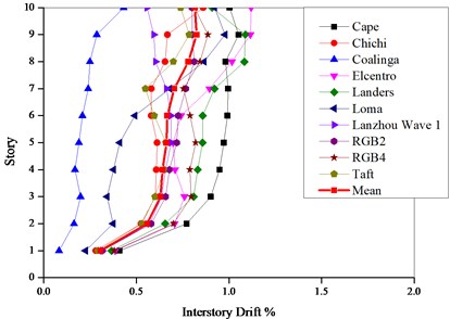
Fig. 9Maximum interstory drift ratios under major earthquake
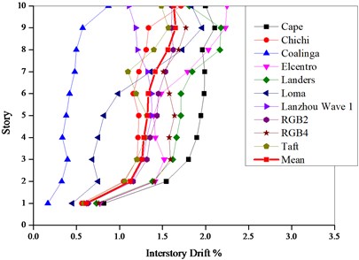
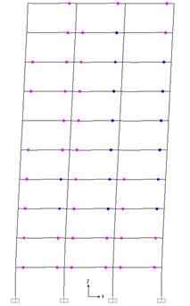
Fig. 10Plastic hinge distribution of PBPD frame
From Figs. 8-9, the maximum interstory drift ratios are comparatively uniform along the height of structure (except the first story) under all the seismic waves except Elcentro and Loma wave. The means of the interstory drift ratio respectively follows within 0.56 %-0.81 % and 1.12 %-1.6 % under the moderate and major earthquakes, which indicates that the inelastic activity is more evenly distributed over the height and the seismic energy can be dissipated simultaneously by each floor. Unlike the traditional design method, the seismic energy can be dissipated only by one story or several soft stories. The results indicate that the mean maximum interstory drifts of the PBPD frame are well less than the corresponding target values.
The plastic hinge distribution under the major earthquake is shown in Fig. 10. It can be indicated from Fig. 10 that the plastic hinges form on either end of each beam meeting the desired yield mechanism. However, the plastic hinges do not form on the column bases due to the conservative design of the first story.
6. Pushover analysis
Aiming at the steel frames designed according to the current code and PBPD method, Pushover analyses are performed on these two frames by SAP2000. Adopt the inverted triangular distribution of lateral force, respectively push the structures to the top displacement of 720 mm and 1080 mm, and the interstory drift of each story is shown in Figs. 11-12.
As shown in Figs. 11-12, compared to the traditional steel frames, the PBPD frames present the more evenly distributed interstory drift, which indicates that the inelastic activity of PBPD frames is more uniformly distributed along the height of structure than the traditional frames and the PBPD frames display the more desirable seismic performance.
Fig. 11Drift ratio under Pushover at 2 % roof drift
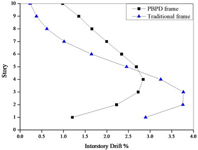
Fig. 12Drift ratio under Pushover at 3 % roof drift
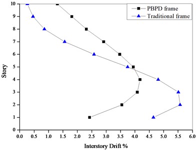
Fig. 13Plastic hinges under pushover at 4 % roof drift
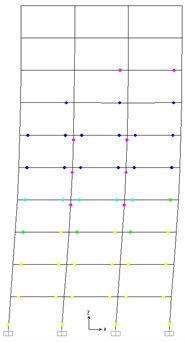
a) Traditional frame
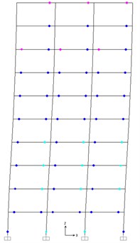
b) PBPD frame
Fig. 13 shows the distribution of plastic hinges of the traditional frames and PBPD frame when these two frames are pushed up to 4 % roof drift. From Fig. 13, for PBPD frames, the plastic hinges desirably appear at both ends of the beams, and no unintended plastic hinges occur in the columns. For the traditional frames, the plastic hinges form in the beams of each story, but there are also plastic hinges in the columns of the 1st story and 4-6 stories. Fig. 13 demonstrates that the deformation distribution of plastic hinges in the PBPD frames is more uniform along the height than those of the traditional frames, which demonstrates that the PBPD frame exhibit an excellent seismic performance.
7. Conclusions
1) The PBPD method uses predetermined target drift and yield mechanisms as important performance objectives. During the design process, the PBPD method can introduce structural nonlinear behavior directly and key performance criteria. Accordingly, the utilization of the PBPD method in the design of high-rise steel frames can eliminate the need for any assessment or iteration after initial design.
2) Through the comparison of seismic performances between the PBPD frame and traditional frame assessed by the nonlinear static analysis and dynamic time history analysis, the validity and reliability of the PBPD design method is demonstrated. In contrast to the traditional frame, the inelastic activity of the PBPD frame along the building height tends to more evenly distributed, which means that the PBPD frame exhibit an excellent seismic performance.
3) The method in this paper can be used to design the steel frame under different performance levels and to control the performance of the steel frame under frequent intensity, basic intensity, and infrequent intensity of the earthquakes.
References
-
Code for Seismic Design of Buildings. GB50011-2010, China Architecture and Building Press, Beijing, China, 2010.
-
Fan C. L., Zhang S. Y., Lu G. Y. Study on rigid-plastic seismic design of reinforced concrete frame structures. World Earthquake Engineering, Vol. 25, Issue 3, 2009, p. 67-73.
-
Fan C. L. Study on Performance Based Rigid-Plastic Seismic Design Method to Reinforced Concrete Structures under Strong Earthquake. Ph.D. Dissertation, Taiyuan University of Technology, Taiyuan, China, 2010.
-
Xin L., Liang X. W., Bai L. Optimal method for direct displacement-based seismic design of RC frames. Journal of Earthquake Engineering and Engineering Vibration, Vol. 28, Issue 5, 2008, p. 79-86, (in Chinese).
-
Medhekar M. S., Kennedy D. J. L. Displacement-based seismic design of buildings-application. Engineering Structures, Vol. 22, Issue 3, 2000, p. 210-221.
-
Ghorbanie-AslM. Performance-Based Seismic Design of Building Structures. Ph.D. Dissertation, Carleton University, Carleton, Canada, 2007.
-
Next-Generation Performance-Based Seismic Design Guidelines-Program Plan for New and Existing Buildings. FEMA 445, Federal Emergency Management Agency, Washington D.C., USA, 2006.
-
Zhou L. Performance-Based Seismic Design of Steel Moment Frames-Yield Point Spectra Method. Master Thesis, Suzhou University of Science and Technology, Suzhou, China, 2011.
-
Abdollahzadeh G. H., Banihashemi M. R. Response modification factor of dual moment resistant frame with buckling resistant brace. Steel and Composite Structures, Vol. 14, Issue 6, 2013, p. 621-636.
-
Sahoo D. R., Chao S. H. Performance-based plastic design method for buckling-restrained braced frames. Engineering Structures, Vol. 32, Issue 9, 2010, p. 2950-2958.
-
Bayat M. R. Performance-Based Plastic Design of Earthquake Resistant Steel Structures: Concentrically Braced Frames, Tall Moment Frames, Plate Shear Wall Frames. Ph.D. Dissertation, The University of Texas at Arlington, Texas, USA, 2010.
-
Leelataviwat S., Saewon W., Goel, S. C. Application of energy balance concept in seismic evaluation of structures. Journal of Structural Engineering, Vol. 135, Issue 2, 2009, p. 113-121.
-
Tehranizadeh M., Moshref A. Performance-based optimization of steel moment resisting frames. Scientia Iranica, Vol. 18, Issue 2, 2011, p. 198-204.
-
Trica L., Chen L. The influence of lateral load patterns on the seismic design of zipper braced frames. Engineering Structures, Vol. 40, Issue 7, 2012, p. 536-555.
-
Khoshnoudian F., Kiani M., Yang T. Y. A new pushover procedure for two-way asymmetric-plan tall buildings under bidirectional earthquakes. Structural Design of Tall and Special Buildings, Vol. 23, Issue 14, 2014, p. 1097-1117.
-
Etedali S., Irandegani M. A. A proposed lateral load pattern for pushover analysis of structures subjected to earthquake excitations. Journal of Vibroengineering, Vol. 17, Issue 3, 2015, p. 1363-1371.
-
Belejo A., Bento R. Improved modal pushover analysis in seismic assessment of asymmetric plan buildings under the influence of one and two horizontal components of ground motions. Soil Dynamics and Earthquake Engineering, Vol. 87, 2016, p. 1-15.
-
Leelataviwat S., Goel S. C., Stojadinovic B. Toward performance-based seismic design of structures. Earthquake Spectra, Vol. 15, Issue 3, 1999, p. 435-461.
-
Lee S. S., Goel S. C. Performance-Based Design of Steel Moment Frames Using Target Drift and Yield Mechanism. Report No. UMCEE 01-17, Department of Civil and Environmental Engineering, University of Michigan, Ann Arbor, USA, 2001.
-
Chao S. H., Goel S. C. Performance-based design of eccentrically braced frames using target drift and yield mechanism. AISC Engineering Journal, Vol. 43, Issue 3, 2006, p. 173-200.
-
Chao S. H., Goel S. C. A seismic design method for steel concentric braced frames (CBF) for enhanced performance. Proceedings of Fourth International Conference on Earthquake Engineering, Taipei, Taiwan, 2006, p. 227.
-
Chao S. H., Goel S. C. Performance-based plastic design of seismic resistant special truss moment frames. AISC Engineering Journal, Vol. 45, Issue 2, 2008, p. 127-150.
-
Goel S. C., Liao W. C., Bayat M. R., Chao S. H. Performance-based plastic design (PBPD) method for earthquake-resistant structures: an overview. The Structural Design of Tall and Special Buildings, Vol. 19, Issues 1-2, 2009, p. 115-137.
-
Liao W. C., Goel S. C. Performance-based plastic design and energy-based evaluation of seismic resistant RC moment frame. Journal of Marine Science and Technology, Vol. 20, Issue 3, 2012, p. 304-310.
-
Liao W. C., Goel S. C. Performance-based seismic design of RC SMF using target drift and yield mechanism as performance criteria. Advances in Structural Engineering, Vol. 17, Issue 4, 2014, p. 529-542.
-
Lee S. S. Performance-Based Design of Moment Frames Using Target Drift and Yield Mechanism. Ph.D. Thesis, The University of Michigan, Michigan, USA, 2002.
-
Load Code for the Design of Building Structures. GB50009-2012, Architecture and Building Press, Beijing, China, 2012.
-
Prestandard and Commentary for the Seismic Rehabilitation of Buildings. FEMA 356, Federal Emergency Management Agency, Washington D.C., USA, 2000.
Cited by
About this article
The author would like to acknowledge the financial support from the National Natural Science Foundation of China (Nos. 51678480, 51108035, 51208058, 51178388), the Natural Science Basic Research Plan in Shaanxi Province of China (No. 2016JM5007, No. 2013JM7030), and the Special Fund for Basic Scientific Research of Central College (No. 310828162017, No. 310828161009), Scientific Research Plan of Xi’an Eurasia University (No. 12-ZKB-05). Research Project of Shaanxi Provincial Department of Education (No. 14JK2073).
