Abstract
The article considers the technology absorption natural gas dehydration, systematization of the physical processes occurring in the technological chain of preparation of natural gas. Built fuzzy causal model of the process gas drying based on the combined application of fuzzy inference and neural network approximation. The use of the model enables the structural and parametric optimization of production, aimed at improving the quality of preparation of natural gas.
1. Introduction
The water present in the gas in the vapor state, forms with methane, ethane and propane, the hydrocarbon hydrates, the settling in the pipeline in a solid phase [1]. To avoid the formation of hydrates, it is necessary to drain the gas. The moisture content in the gas is characterized dewpoint temperature value. Dew point is known as the temperature cools down to a moisture content at a constant gas reaches full saturation with water vapor and condensation of water vapor contained in the gas. Preparation of gas in field conditions is the removal of the condensate water [2].
Consider technology absorption dehydration of natural gas with the use of diethylene glycol as an absorbent in preparation for transport [3]. Gas from wells, is pre-cleaned in the centrifugal apparatus. After the booster compressor station (BCS) and the passage of air coolers of gas absorption process of drying is carried out. After passing the second stage compression BCS gas is transportation. The indicator is the moisture content of the dew point temperature (DPT). In accordance with OST 51.40-93 DPT value for temperate areas of: –3S summer, winter –5C. For cold areas, these values 10C and 20C, respectively.
Natural gas treatment system can consist of several types of elements. First of all, this apparatus and process equipment. The system also includes maintenance personnel, production wells, external conditions, including weather. The aim of the system is to ensure that the desired properties of natural gas with minimum cost expenditures. Elements of the system are interconnected relationships, characterized by some of the variables and parameters.
2. The model of the system
Hardware exercising process, presented in the form of some converters that transform the values of input variables in the weekend. Let there be a central element . Together with the elements , , , an element forms a subsystem. Entrances to subsystem determines the relationship , , and outputs connections , . Nodal element carries out transformation of the form:
where – output actions; – input actions.
For example, the inlet separator provides a preliminary separation of the condensate from the gas [4]. Driving separator shown in Fig. 1.
The crude gas is fed into the machine through the radial connector located on the fender gas inlet plate assembly for pre-separation of large liquid droplets and mechanical impurities. Due to the centrifugal effect created by the gas input node on the unit deposited liquid droplets and solid particles that drain into a collection of impurities through the annular gap between the housing and the protective sheet. After pre-cleaning gas is distributed evenly between the centrifugal elements in which it is separated from the liquid fine particles of the purified gas leaves the top of the elements and the liquid gets on the grid, so that by draining pipe drains into a collection of impurities. Grid centrifugal elements separates the raw gas from the purified. The liquid, which is in the collection of impurities is discharged from the machine to the drainage pipe [5, 6].
Fig. 1Scheme inlet separator
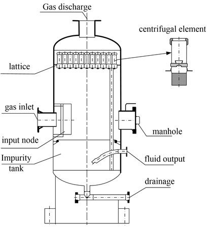
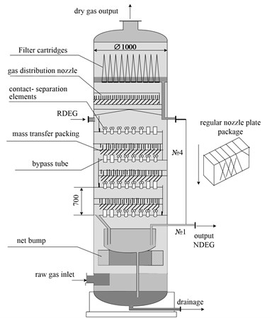
Fig. 2Shema absorber
In this case, the input parameters are the thermodynamic (pressure, temperature, humidity) and thermal characteristics of the gas. For input parameters also include the technological characteristics of the process (the gas flow rate, gas twist, disperse composition of condensed moisture, the design features of the device, etc.). The output parameters include pressure, temperature, gas flow rate, moisture content.
Conversion (1) may be a mathematical model of the process. The model can include equations of motion of multiphase medium in a multidimensional setting with phase transformations. Conversion may also appear as an engineering method of calculation of technical and economic parameters of the process. A more convenient system for the submission process is a mathematical model describing the neural network. Trained on a limited set of training samples containing experimental data network summarizes the accumulated information, and outputs the response to the data, is not used for teaching.
For the drying gas used absorbers of various types (Fig. 2). The most widely used installation applying diethylene glycol (DEG).
For the dehydration gas is used an aqueous solution of diethylene glycol. It absorbs moisture from the gas. Saturated water solution is easily recovered by evaporation of excess water. Gas enters the bottom of absorption column - a tower with a cap number of multiple plates. The lower part of the column is a scrubber, which serves to trap the condensed raw gas phase. Towards the rises in a column (in plates) gas down the aqueous solution of diethylene glycol, part of the column above the top plate and coming out of the middle column. Before leaving it accumulates in the annular space below the bottom plate. In the area of the scrubber diethylene misses. Release glycol regulated automatic float level control. Liquid settles in the lower scrubber is discharged through the drain hole. At the top of the absorption column above the top tray is a second scrubber. It is designed to hold the absorbent liquid droplets entrained in the gas. After passing the upper scrubber dried gas leaves the column.
For input variables discussed above, are added to the characteristics of the feed DEG. For output variables, in addition to the characteristics of dry gas, are added to the properties of saturated diethylene glycol carryover NDEG together with the gas.
A solution of diethylene glycol, swallowed water from the gas goes to regeneration. First it passes through the heat exchanger, where it is warm towards diethylene glycol, released from the evaporator. The heat exchange apparatus of diethylene glycol containing water is heated and goes into the flash column in which the water evaporates from this diethylene glycol.
Equipment installed on the gas treatment plants, operating under conditions of varying technological parameters of the prepared gas. Mining enterprises are faced with the problem of gas quality in the late stages of field development. Process gas treatment plant equipment must provide the required gas quality indicators in unstable conditions. In addition, you must take into account the increased requirements to the quality of the gas preparation and reliability of the equipment to ensure the basic indicators (providing the dew point, condensation reduction of losses, the absorbent hydrate inhibitors). Therefore, there is a constant improvement of the mass transfer devices through the use of various types of composite structures contact devices. For example, the applied centrifugal elements mounted on them and regular packing packets (Fig. 1). In this case, at high loads on the gas centrifugal separation contact-elements operate in a liquid dispersion mode (DEG) swirling gas flow to form a developed surface mass transfer. Nozzle surface due to a large free section, close to the cross section between poppet space, for a given operating mode, mainly, in the separation mode, as a process for mass transfer occurs between the nozzle and the gas flow with entrained liquid components. At low load operation of the combined gas contact step is characterized in that in this mode centrifugal contact – separation elements operate longer in a liquid dispersion operation, and the disruption of the film from the wall of the centrifugal nozzle and its runoff down. As a result, set in space between poppet regular nozzle plate works in irrigation mode (surface becomes mass transfer, with significantly greater than the mass transfer surface elements). This preserves the effectiveness of the process of gas dehydration. Application of section catching DEG (a dish with a filter – cartridges) allows the nozzle packages by reducing the gas flow rate to the gas velocity in the section of the apparatus to improve the quality of liquid separation, carried away by the mass transfer from the upper plate. The decrease in the removal of fluid filter – cartridges increases the turnaround time of their work and reduce losses from DEG with dry gas from the absorber. Application of the principles of uniform gas distribution over the cross section of the device allow the typical solutions to modernize absorbers of different designs.
Thus, in the preparation of the block diagram of the process of preparation of natural gas as the elements of the system should add additional structural devices that alter the characteristics of the drying process. For example, an effective way to improve the temperature and pressure parameters of the process is the use of a two-stage drying technology at two temperature and pressure levels. In this case, the input separators upgraded regularly nozzle plate feed saturated DEG. As a result, significantly improve the working conditions of booster units of the first stage of compression.
The introduction of additional structural elements on the one hand alter the characteristics of the gas, usually in the direction of improvement, but at the same time changes the costs of cost process typically upwards. Therefore, to be considered as variables of the system and cost characteristics.
3. The fuzzy control model
Consider the block diagram of the process of natural gas preparation process (Fig. 3).
Structural elements of this system are:
CGC – centrifugal gas cleaning;
BCS + AC – booster compressor station + air coolers;
A – absorber; S – stripper; ME – modernized equipment.
The system has the properties described by the following input variables:
– gas consumption; – input pressure; – gas temperature; – moisture contents; – the cost of upgrading the drying gas in the CGC; – the cost of upgrading the drying gas in the absorber; – the cost of an additional drying gas in the absorber; – air temperature; – qualification of staff; – upgrade costs recovery DEG.
The output variables of the system are:
– dew point temperature; – the cost of drying gas; – the total carryover DEG.
Intermediate variables:
– DEG; - pressure; – gas temperature; – moisture contents.
To consider the scheme of the process is assigned a fuzzy causal model, the structure of which is shown in Fig. 4.
Fig. 3Structure of technology system natural gas treatment process
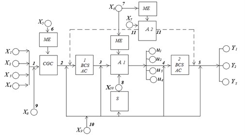
Fig. 4The structure of the fuzzy model
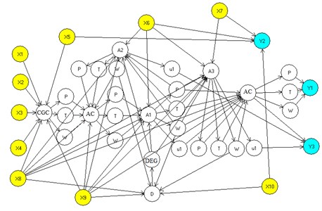
The relationship between these elements of the system are divided into two groups. The first group represents a transformation that alter properties of the gas being processed in the process equipment. This conversion is performed using a neural network of the form:
where – transformation matrix coefficients determined in the process of network training.
The training set contains the results of tests and measurement devices obtained during the operation of the equipment.
The first group relations include communication devices corresponding to the centrifugal gas purification, BCS + AC and absorbers. Inputs transformations are expendable and thermodynamic characteristics of the gas. Consumables-gas thermodynamic characteristics match and output variables.
The second group of relations is based on expert opinions and methods of fuzzy inference. The basis for the operation of fuzzy inference is the kind of relations between the elements of the fuzzy system, containing rules, the names and functions of the terms of the terms belonging.
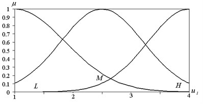
Consider the way of defining relations of the second type on the example of relation . For the linguistic input variable (the cost of upgrading the drying gas in the absorber) introduced three terms: – low; – Average; – The high costs of modernization. Output variables (diethylene entrainment) and (moisture contents) are also three terms. For variable : – a slight decrease in ash; – Average reduction in ash; – A significant reduction in entrainment. For variable : – a small reduction in the moisture content; – Average reduction in the moisture content; – Significant reduction in moisture content.
Membership functions for the variable shown in Fig. 5.
Costs are measured by the value of a notional unit. Membership functions for the variable shown in Fig. 6.
Fig. 5Membership function for the costs for the modernization
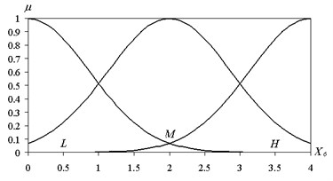
Fig. 6Membership function for the measure reducing entrainment DEG
There decrease ash DEG occurs in time.
The relevant set of rules for the inference is as follows:
The value of the variable corresponding to the element with the incoming communication is a weighted summation of all incoming calls:
where – the weights that determine the contribution of the th regard to the state of the th element. The coefficients shall be determined in the process of learning fuzzy network.
When the structural optimization of small factors lead to the rejection of connection or edges of the graph in Fig. 7.
Training data are characteristics of the operational process , . Training is conducted by using a genetic algorithm.
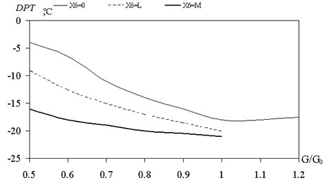
The calculated output value of the dew point temperature (DTP), depending on the gas flow rate at different levels of the cost of the modernization of the drying process shown in Fig. 7.
The calculation for the winter period of time to change the amount applied to the preparation of natural gas. The value corresponds to the optimal level boot process equipment . Due to the additional funds allocated for modernization at the secondary level may be reduced to 12 degrees while reducing gas consumption by 2 times.
The model constructed of natural gas treatment system provides a response output variable to changes in the input variables of the form:
With an appropriate choice of the system optimality criterion on the basis of the transformation Eq. (2) it is possible to put the problem of finding the optimal structure of the process flowsheet.
Fig. 7The dependence of the degree of DPT loading equipment and modernization costs
4. Conclusions
Ordering of the physical processes occurring in the technological chain of preparation of natural gas, it possible to establish the main factors affecting the drying options: high-speed mode of movement dispersed-annular flow in the mass transfer elements; temperature, pressure and humidity of the gas; concentration of the absorbent.
A complex process modeling method using a causal network based on the combined use of fuzzy inference and neural network approximation. The method of teaching fuzzy network models using genetic algorithm with real-coded.
Built on the basis of empirical data and expert, fuzzy simulation model of the process of natural gas treatment process allows for changing production conditions a rapid assessment of the natural gas indices prepared for transport. The use of the model enables the structural and parametric optimization of production, aimed at improving the quality of preparation of natural gas.
References
-
Istomin V. A., Yakushev V. S. Gas Hydrates under Natural Conditions. Nedra, Moscow, 1992, p. 235, (in Russian).
-
Strizhov J. H., Khodanovich I. E. Gas Production. Institute of Computer Science, Moscow-Izhevsk, 2003, p. 376, (in Russian).
-
Vyahirev R. I., Gritsenko A. I., Ter-Sarkisov R. M. Development and Exploitation of Gas Fields. Nedra, Moscow, 2002, p. 890, (in Russian).
-
Abasov M. T., Jalilov K. N. Questions Underground Hydrodynamics and Development of Oil and Gas Fields. Azerneftneshr, Baku, 1960, p. 255. (in Russian).
-
Cooper C. D. Air Pollution Control Methods. Kirk-Othmer Encyclopedia of Chemical. Technology. Wiley-Interscience, New York, 2007.
-
Laso M., von Stockar U. Absorption. Kirk-Othmer Encyclopedia of Chemical Technology. Wiley-Interscience, New York, 2007.
