Abstract
According to the requirement of small satellite, this paper designed a digital sun sensor which diaphragm is a V-shaped cross-section structure. Using Position Sensitive Detector (PSD) as the light detector, we designed the V-shaped cross-section structure based on the pinhole imaging principle. The sun sensor realized the accurate calculation for two axis sun angle of the sun sensor. The mechanical test, thermal test and testing of the sun sensor are designed and carried out. The mechanical test and thermal test results verify the stability of the sun sensor. Testing result shows that the detection angle can reach (120°)×(120°), and the attitude determination accuracy is better than 6” in the entire viewing field. The mass, volume and power consumption of the sun sensor is 0.177 kg, 78 mm×77 mm×21 mm and 0.25 W. The sun sensor has low power consumption, large viewing angle and high precision characteristics, which realized the sun sensor the miniaturization and meet the requirements of the micro satellite. Its performance has been verified in orbit.
1. Introductions
The sun sensor is an important attitude control component on the spacecraft. The satellite gets the sun vector location information, in the satellite body coordinate system by the sun sensor, to measure, confirm and control the satellite’s attitude [1-5]. From the sun sensor, the satellite can also get satellite spin rate and phase information in the spin of the satellite. In the early stage of the sun sensor, the azimuth information of the incident sun light is obtained by measuring the current output of the optical elements such as the photoelectric cell. Soon a new digital sun sensor which optoelectronics adopt image sensor appears. Compared with the optical cell, the basic detection unit of the image sensor has increased from a few to hundreds, or even tens of thousands, which greatly improves the ability of the sun sensor to perceive the solar light [6, 7]. Due to the limitation of the image sensor image plane size and the installation position of the mask plate, the sun sensor cannot work when the initial angle of the attitude is not in the viewing field. In order to solve this problem, many researchers have carried out relevant research, such as designing a special spherical mask structure or combining multiple sun sensors into one sun sensor [8].
With the vigorous development of micro satellite and the increasing requirements of the attitude control accuracy, the sun sensor is becoming gradually modular, miniaturization and long life. To some extent, although the above design increases the sun sensor's viewing field, while it also brings a series of problems, including increasing the system volume, mass, or power, even at the cost of the accuracy of the sun sensor, which is obviously not suitable for micro satellites.
According to the requirements of the micro satellite for the sun sensor, based on the V-shaped cross structure (the diaphragm) and the PSD (as the light detector), this paper designs a digital sun sensor. Through the one-dimensional PSD and the diaphragm, the sun sensor realizes the two axes solar angles accurate calculation. The mass, volume and power consumption of the sun sensor is 0.177 kg, 78 mm×77 mm×21 mm and 0.25 W which meet the application requirements of micro satellite.
2. The design principle of sun sensor
2.1. The PSD working mechanism
With the advantages of high position resolution, simple reaction current and quick response, PSD is widely used in the non-contact optical displacement detection system [10]. The PSD section structure is shown in Fig. 1. When the incident light beam irradiating on the surface of the photosensitive, the charge is generated at the incident position and the intensity, which is proportional to the light intensity. The charge flows through the P-layer to the electrode. Since the resistance of the P-layer is uniform, the current output from the two poles is inversely proportional to the distance from the point of light to the poles.
The distance of the two electrodes is 2, and the output light current of the electrode (1) and (2) are respectively and , and the total output current of electrode (3) is shown as the Eq. (1):
Fig. 1Cross-section structure schematic plan of PSD[11]
![Cross-section structure schematic plan of PSD[11]](https://static-01.extrica.com/articles/17518/17518-img1.jpg)
Regarding PSD as the establishment of the center of the coordinate system, the distance between the point of light spot and the center points , we get:
From the Eq. (1)-(3), the distance between the center point and the point of light, we get:
The Eq. (2) and (3) show that the movement of the carrier in the substrate is separated by the Ohm’s Law, which means
The position information is determined by detecting the movement of the photo generated charge on the substrate, while it has no relationship with the intensity, distribution, symmetry and size of the light spot on the surface [12]. The structure and equivalent circuit of one dimensional PSD are shown in Fig. 2.
Measurement range and measurement accuracy are the main basis for the selection of photoelectric detector. The measuring range of the system is ±0.5 mm, and measuring precision is ±0.001 mm. In this paper, we select the one-dimensional PSD, that its light receiving area is 81 mm2, nonlinear RMS is less than 0.15 %, and typical position error is ±5 μm, as the photoelectric displacement detection device, which produced by the Hamamatsu company.
Fig. 2One-dimension PSD [11]
![One-dimension PSD [11]](https://static-01.extrica.com/articles/17518/17518-img2.jpg)
a) Structure schematic plan
![One-dimension PSD [11]](https://static-01.extrica.com/articles/17518/17518-img3.jpg)
b) Equivalent circuit
2.2. The principles of optics
The sun imaged on the PSD through the hole on the diaphragm. By calculating the distance from the initial center position to the sun image point, we can determine the relationship between the azimuth angle of the sun light and the fixed coordinate system. The digital sun sensor optics principle is shown in Fig. 3 [13].
Fig. 3Sun sensor optics principle
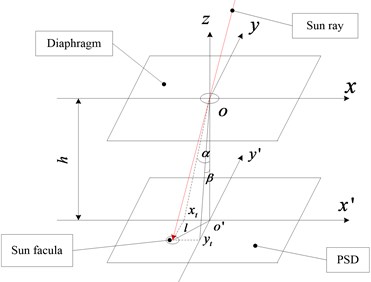
Assuming that the distance between the diaphragm and the PSD plane is , and the relative moving distance between the sun facula that the incident angle of the sun ray is and the vertical incident sun ray is . represents the two axis (-axis and -axis) sun angle. represents the distance between the sun facula centroid to . So, the sun angle is expressed as Eq. (5):
Resolution is:
where, is the minimum resolution for PSD.
The calculation formula for the single axis viewing angle of the sun sensor is:
where, is the length of the PSD sensitive element in the horizontal (-axis or - axis).
3. The structure design of the sun sensor
According to the overall structure requirements of the micro satellite, the sun sensor is designed, and the model is shown in Fig. 4. The mask plate has a particular requirement for the location, and taking into account the processing technology, the diaphragm has been designed into two parts including the upper and lower sections. Located inside the diaphragm, the mask plate with three U-shaped grooves in uniform edges is spliced by epoxy glue which is dedicated glue in aerospace [14]. The positional relationship between the internal components of the sun sensor is shown in Fig. 5. The size of the main devices is shown in Table 1.
Fig. 4Sun sensor model
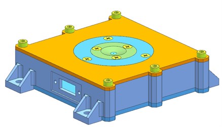
a) Sun sensor 3D model
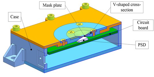
b) Sectional view of the main components
Fig. 5Internal device positional relationship
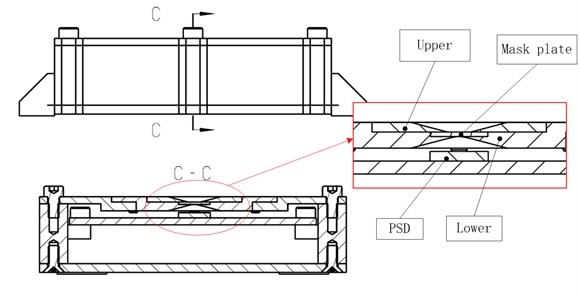
4. Experiments
The satellite will be subjected to harsh mechanical environment which be passed by the rocket during launching. In orbit, the satellite is in a space of high and low temperature environment, and itis in alternating high and low temperature environments in orbit. It is necessary to carry out mechanical test and high temperature test on the sun sensor, and to test the performance of the sun sensor in the ground.
Table 1Sun sensor size
Name | Size (unit: mm) |
Sun sensor | 78×77×21 |
PSD | 9×9×1.5 |
Circuit | 70×70×2 |
Mask plate | (Ø9, Ø0.5)×0.7 |
Diaphragm | (Ø15, Ø3.8, 150°)×1.5 |
4.1. Mechanical test
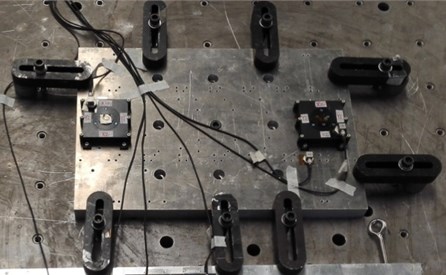
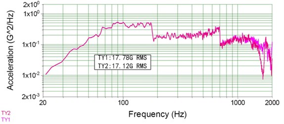
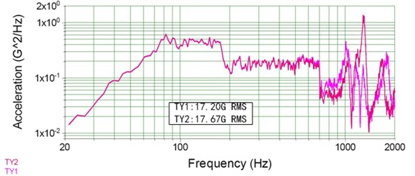
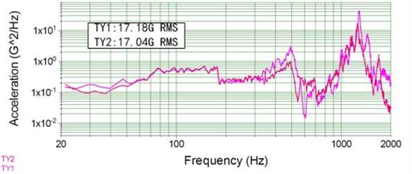
The component-level random vibration forced acceleration power spectral density RMS value of a micro-satellite is 14.53 g. The test conditions are shown in Table 2. The -axis, axis and - axis random vibration test were respectively carried out with 20 mechanical vibration test bench to assess the structural strength of the sun sensor. The mechanical test site is shown in Fig. 6. The random vibration response curves of -axis, -axis and -axis of the sun sensor are shown in Fig. 7.
Table 2The Acceleration power spectrum (APS)
Frequency (Hz) | APS |
20-80 | +8 dB/oct |
80-180 | 0.45 g2/Hz |
180-700 | 0.18 g2/Hz |
700-1700 | 0.05 g2/Hz |
1700-2000 | –6 dB/oct |
Fig. 6Mechanical test site
From Fig. 7, we can see that the RMS values of the random vibration response of the sun sensor are all in 20 g, which can meet the overall design index of the satellite.
4.2. High temperature test
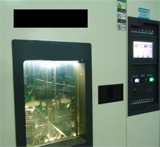
For the assessment of sun sensor in thermal stability, according to a small satellite component level thermal cycling test conditions, using DHS-800 high low temperature test box to test sun sensor at atmospheric pressure with –5 °C-+35 °C in 8.5 times at low temperature and high temperature cycling test. The high and low temperature test site is shown in Fig. 8.
Fig. 7The random vibration response curves
a)-axis
b)-axis
c)-axis
Fig. 8High and low temperature test site
4.3. The performance test
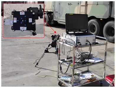
In order to test the performance of the sun sensor after mechanical test and thermal cycling test, the field experiment was carried out on the sun sensor. As shown in Fig. 9, the sun sensor test system including sun sensor, a tripod, a turntable fixing piece, a three axis turntable composition. Testing carried out under cloudless weather. Turntable console can accurately control the rotation angle and position of the turntable; the accuracy can reach 4″. Deflect two axis measurement accuracy tests on sun sensor.
According to the test data, the repeatability measurement error is less than 60″. In the whole field of view rotation measurement, the maximum error of the sun angle measurement and the actual value is within 40′. The sensor realized (120°)×(120°) to measure the sun angle, the field of view the default position accuracy is superior to 6″.
Fig. 9Performance test site
5. Conclusions
According to the requirements of a small satellite, this paper designed a digital sun sensor which diaphragm is a V-shaped cross-section structure. Using PSD as the light detector, and the results are as follows.
1) Through the design of V-shaped cross-section structure to introduce sun rays into the sun sensor, the sun sensor realized two axis sun angle accurate calculation. Thermal and mechanical testing verifies the sun sensor structure is stable and reliable.
2) The test shows that the mask plate can effectively reduce the intensity of the sun, filter out other stray light interference, making the sun spot like clear, regular and uniform brightness.
3) Using PSD as the light detector, the repeatability measurement error is less than 60″. In the whole field of view rotation measurement, the maximum error of the sun angle measurement and the actual value is within 40′. The sensor realized (120°)×(120°) to measure the sun angle, the field of view the default position accuracy is superior to 6″.
4) The mass, volume and power consumption of the sun sensor is 0.177 kg, 78 mm×77 mm×21 mm and 0.25 W. The sun sensor has low power consumption, large viewing angle and high precision characteristics, which realized the sun sensor the miniaturization and meet the requirements of the micro satellite. Its performance has been verified on micro satellite in orbit.
References
-
Chang Y. K., Lee B. H., Kang S. J. High-accuracy image centroiding algorithm for CMOS-based digital sun sensors. Sensors, 2007, p. 329-336.
-
Enright J., Sinclair D., Li C. Embedded algorithms for the SS-411 digital sun sensor. Acta Astronautica, Vol. 64, Issue 9, 2009, p. 906-924.
-
Lee C., Bae S. Y., Mobasser S., et al. A novel silicon nanotips antireflection surface for the micro sun sensor. Nano Letters, Vol. 5, Issue 12, 2005, p. 2438-2442.
-
Enright J. P. Design optimization of a digital sun sensor for use with parametric processing. IEEE Transactions on Instrumentation and Measurement, Vol. 57, Issue 10, 2008, p. 2188-2195.
-
Shuster M. D. A survey of attitude representations. Navigation, Vol. 8, Issue 9, 1993, p. 439-517.
-
Lepage G., Bogaerts J., Meynants G. Time-delay-integration architectures in CMOS image sensors. IEEE Transactions on Electron Devices, Vol. 56, Issue 11, 2009, p. 2524-2533.
-
Yu H., Qian X., Chen S., et al. A Time-Delay-Integration CMOS image sensor with pipelined charge transfer architecture. IEEE International Symposium on Circuits and Systems (ISCAS), 2012, p. 1624-1627.
-
Tu B. J., Han K., Wang H., et al. Design of digital sun sensor with large field. Chinese Journal of Sensors and Actuators, Vol. 24, Issue 3, 2011, p. 336-341, (in Chinese).
-
Bouwmeester J., Guo J. Survey of worldwide pico-and nanosatellite missions, distributions and subsystem technology. Acta Astronautica, Vol. 67, Issue 7, 2010, p. 854-862.
-
Ding X. K., Liu T. G., Song D. Y. Impact of accuracy of laser spot quality in laser triangulation long term continuous measuring based on PSD. Chinese Journal of Lasers, Vol. 39, Issue 2, 2012, p. 1-, .(in Chinese).
-
Duan J., Sun X. Y., Cai J. H., et al. Applications research to PSD in the laser displacement detecting system. Infrared and Laser Engineering, Vol. 39, 2007, p. 281-284, (in Chinese).
-
Zhang F., Li Y., Li H., et al. Compensation method of PSD’s background light based on improved BP neural network. International Symposium on Instrumentation and Measurement, Sensor Network and Automation (IMSNA), Vol. 1, 2012, p. 151-153.
-
Gannon J. L., Li X., Heynderickx D. Pitch angle distribution analysis of radiation belt electrons based on combined release and radiation effects satellite medium electrons A data. Journal of Geophysical Research: Space Physics, Vol. 112, Issue A5, 2007.
-
Mammini P. V., Nordt A. A., Holmes B., et al. Sensitivity evaluation of mounting optics using elastomer and bipod flexures. Optical Science and Technology, SPIE’s 48th Annual Meeting, International Society for Optics and Photonics, 2003, p. 26-35.
About this article
The authors would like to thank the financial support of The National Natural Science Foundation of China (No. 41501383).

