Abstract
The lecture deals with the stability of the movement of the journal inside the hydrodynamic plain bearings, which limits the operating rotational speed. The purpose of active vibration control using piezoactuators is to increase the limit of the rotor stable rotation speed and control the journal position. Besides theory it will be presented the results of testing the first prototype of this type of the bearings.
1. Introduction
The advantage of journal hydrodynamic bearings (alternatively called sleeve bearings or plain bearings for radial load) is high radial load capacity and operation at high speeds. The disadvantage is the excitation of shaft vibrations, called an oil whirl, after crossing a certain threshold rotational speed which is dependent on the radial bearing clearance and the viscosity of lubricating oil. Once an unstable motion of the bearing journal occurs, the machine starts to vibrate and its operating speed cannot be increased. Demonstration of the rotor instability is shown in Fig. 1.
Fig. 1Sliding hydrodynamic bearings instability due to the oil film
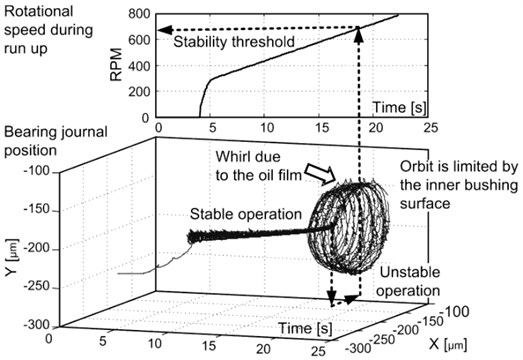
A passive way how to prevent vibrations due to the oil film whirl consists in varying the bearing internal clearance, such as to use lemon or elliptical bore, cutting a circumferential groove or using tilting pads.
The threshold of stability in angular velocity can be calculated by the Muszynska formula [1]:
where is stiffness of the oil film, is a rotor mass and is a dimensionless parameter, which is slightly less than 0.5.
2. Active vibration control of journal bearings
Vibrations of the shaft can be suppressed using the system for an active vibration damping with piezoelectric actuators to move the bearing bushing in two directions. The motion of the bearing bushing is controlled by the electronic controller, which responds to the change in position of the bearing journal with respect to the bearing housing. The mechanical arrangement of the actively controlled bearing is shown in Fig. 2.
Fig. 2Movable bushing inserted into the housing
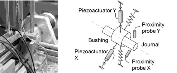
Two stacked linear piezoactuators are used to actuate the position of the bearing journal via the position of the bearing bushing. The position of the journal or shaft is sensed by a pair of capacitive sensors. The system of the actively controlled journal bearings is the 1st functional prototype in the known up to now [2]. It works with a cylindrical bushing which did not require special technology of production and assembly. This new bearing enables not only to damp vibrations, but also serves to maintain the desired bearing journal position with accuracy of micrometers, which is important e.g. for grinding and milling spindles. Active vibration control is a novelty which faces to the mentioned instability of the journal bearings. The working prototype of the active vibration control system for the journal bearings was developed in the Czech Republic.
Many authors pay attention to the active control of the journal bearings with the use of active magnetic bearings (AMB) [3] and giant magnetostrictive material (GMM) [4]. Although the authors of the paper which deals with the use of GMM state those experiments can be carried out up to 1700 RPM, they publish only measurements at 350 RPM. The instability due to the oil film could not arise at this low rotational speed. The advantage of journal bearings with piezoactuators compared to AMB is that the bearing bushing mounting stiffness remains unchanged in the case of an accidental loss of the electric power supply.
3. Test stand and instrumentation
The performance of the actively controlled bearing was tested on the test bench (Rotorkit) with the span of bearing pedestals of 200 mm. The bearing diameter is 30 mm and the length-to-diameter ratio is equal to one, see Fig. 3. An inductive motor of 400 Hz drives the rotor and therefore the maximum rotational speed is 23k RPM. An input for the oil inlet is in the horizontal plane of symmetry of the bushing. As is evident from the photo in Fig. 3 the supports of the piezoactuators were reinforced by additional bars. Bending and torsional load of the piezoactuators are excluded by using flexible tips and mounting procedure.
The position of the bearing journal is measured by a pair of the proximity probes which are capacitive sensors originated from the MICRO-EPSILON company. The sensors are of the capaNCDT CS05 type with a measurement range of 0.5 mm. An advantage of the capacitive sensors is that it is not necessary to ground the shaft. The magnitude of the capacitive sensor error is less than 1 μm. As was stated before the bearing bushings are actuated by means of the piezoactuators oriented in vertical and horizontal directions and fastened to the rig frame. The preloaded open-loop piezoactuators are of the P-844.60 type, the product of the Physik Instrumente Company. The piezoactuator require a low voltage amplifier with the 120 V peak value (LVPZT). The piezoactuator travel range is up to 90 μm, the pushing force is up to 3000 N and the pulling force is only up to 700 N.
Fig. 3Rotorkit

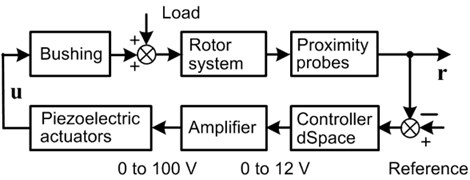
An electronic feedback which is shown in the diagram in Fig. 4 is created for each of the two directions of the motion of the bearing journal in the bearing bushing. The control system is thus composed of two independent loops, each of which has its own controller. Both the controllers are of the proportional type. The controllers were created as a digital in the signal processor of the dSpace type. The sampling frequency is chosen equal to 5 kHz.
If the open-loop gain is positive, then the maximal rotational speed for the rotor stable behavior is as follows:
Fig. 4Active vibration control system
4. Influence of the controller proportional gain on instability threshold of journal bearings
The instability onset of the bearing journal motion inside the bushing arises when crossing the threshold value of rotational speed Eq. (2). This phenomenon means that the steady-state rotation of the journal is not stable and the journal axis starts to whirl at the frequency which is 0.42 to 0.48 multiple of the frequency of rotational speed of the rotor.
The effect of active vibration control for the constant gain of the controller on the threshold of instability is presented in this chapter. Rotor speed increases according to a ramp function as it is shown in the left panel of the Fig. 5. The time history of the axis coordinates of the bearing journal is shown in the right panel of the Fig. 5. The -coordinate corresponds to horizontal direction and the -coordinate is for vertical direction. Active vibration control is switched OFF for this measurement. Instability occurs at about 2k RPM. Oscillations of the bearing journal are limited by the journal clearance within the bushing. Measurements in this article were carried out on the shaft with the radial clearance of 55 μm.
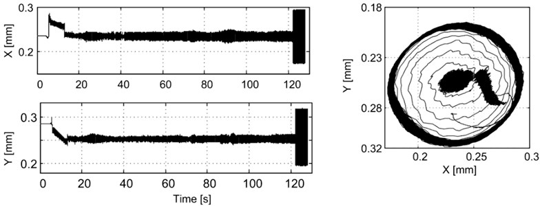
The time histories of the axis coordinate of the bearing journal are also shown in Fig. 6. The active vibration control for these measurements is switched ON. The controller gain for the measurement in Fig. 6 is the maximum value we used for the tests. Instability of the bearing occurs at the rotational speed about 12k RPM. Vibrations during the instable motion of the journal are also limited by the journal clearance within the inner gap of the bearing bushing.
Fig. 5RPM and the journal position as a function of time for tests without active vibration control

The active vibration control is not turned ON at zero RPM of the rotor but after finishing a transient process, which ends by lifting the journal to approximately the middle position in the vertical direction which takes approximately 15 seconds for the given rate of the increase of speed. The transient of the journal seems to be reverse for the vertical motion of the bearing journal in the right panel of the Fig. 5 and in the left panel of the Fig. 6. The scale for the vertical motion is reverse in these figures, meaning upside-down. The relationship between horizontal and vertical movement of the journal shows the orbit in the right panel of Fig. 6. The orbit is a trajectory of the journal axis. The shape of the orbit is approximately circular when instability occurs.
Fig. 6RPM and the journal position as a function of time for tests with active vibration control ON
5. Influence of the parametric excitation on instability threshold of journal bearings
The linear proportional controller was used for active vibration control in the previous chapter. Parametric excitation means that at least one parameter of the system varies periodically in time according to a sinusoidal function. The gain of the proportional controller was selected as this varying parameter. The system becomes non-linear and non-stationary. The gain of the proportional controller is given as follows:
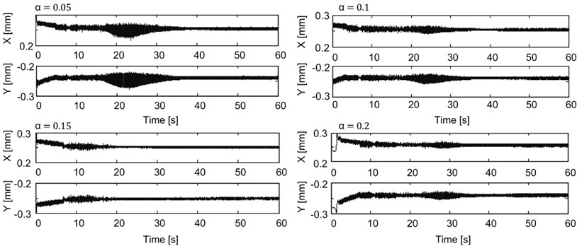
where is a dimensionless amplitude of excitation, is a static gain factor and is angular frequency of excitation. Dohnal [5] has solved a similar problem for magnetic bearings. The experiments on the test stand were conducted for the following amplitudes of excitation 0, 0.1, 0.15, and 0.2. The static gain was the same as the gain of the previous experiments with the linear controller. The excitation frequency was selected 30 Hz, which is approximately equal to the frequency of vibration at the low RPM.
Rotor speed increases according to a ramp function as is shown in the left panel of the Fig. 7. Results of measurement are shown in the two panels as in the previous figures. The time histories in the right panel of the Fig. 7 correspond to an operation when the active vibration control is OFF. The effect of the amplitude of the parametric excitation on the journal movement during RPM run up is shown in Fig. 8. The best choice of the excitation amplitude is 0.15, for which is the position of the journal almost without oscillations. The amplitude of the residual oscillation of the journal does not exceed 8 μm. Precision ball bearings (so called Deep groove ball bearings) which are offered by SKF have a radial clearance (Radial internal clearance C2) to a diameter of 30 mm in the range from 1 to 11 micrometers. The maximum rotational speed of the 206-SFFC bearing type is only 7.5k to 13k RPM.
Fig. 7RPM and the journal position as a function of time for tests with active vibration control OFF

Fig. 8The journal position as a function of time for tests with active vibration control ON
6. Reducing mechanical power losses in actively controlled bearings
Power losses in the journal bearings were estimated from the electric power which is consumed by frequency convertor and motor. Dependence of electrical power upon rotational speed of the motor was measured with and without active control as it is shown in Fig. 9. Basic power consumption of the motor and frequency convertor was measured with the disconnected clutch between the motor and rotor; it means that the bearings were inoperative. The friction loss of a pair of bearings at 7000 rpm is 66 W in an unstable operation, and if the active vibration control is ON, then the friction loss is of only 48 W. The active vibration control reduces the friction losses of sliding bearings by 27 %. The bearing clearance is of 90 μm for the bearing journal of the diameter 30 mm. As a lubricant the hydraulic oil of the OL-P03 type (VG 10 grade, kinematic viscosity 2.5 to 4 mm2/s at 40 °C) was used. All tests were undertaken at ambient temperature about 20 °C.
For small power loss by friction in the bearings the actively controlled bearings can be used in systems for storing the kinetic energy as they are flywheels that spin at high speed. Longer life compared with roller bearings, it is another advantage of this type of bearings [6].
Fig. 9The electric power consumed by the frequency convertor, motor and bearings

7. Conclusions
Experiments prove the correctness of the theoretical prediction which refers to the extending of the operating range of plain bearings when active vibration control is used. The experiments with the time-periodic changes of the controller gain confirm the positive effect on the vibration response. The control system maintains the bearing journal at the chosen position with the same precision as the precision ball bearings. The actively controlled journal bearings reduce the mechanical power losses by friction.
References
-
Muszynska A. Whirl and whip – rotor/bearing stability problems. Journal of Sound and Vibration, Vol. 110, Issue 3, 1986, p. 443-462.
-
Tůma J., Šimek J., Škuta J., Los J. Active vibrations control of journal bearings with the use of piezoactuators. Mechanical Systems and Signal Processing, Vol. 36, 2013, p. 618-629.
-
Fürst S., Ulbrich H. An active support system for rotors with oil-film bearings. Proceedings of IMechE, Series C, 1988, p. 61-68.
-
Lau H. Y., Liu K. P., Wang W., Wong P. L. Feasibility of using giant magnetostrictive material (GMM) based actuators in active control of journal bearing system. Proceedings of the World Congress on Engineering, Vol. 2, London, UK, 2009.
-
Dohnal F., Markert R., Hilsdorf T. Enhancement of external damping of a flexible rotor in active magnetic bearings by time-periodic stiffness. Proceedings of the SIRM, Internationale Tagung Schwingungen in rotierenden Maschinen, Darmstadt, Deutschland, 2011.
-
Zisser M., Schweighofer B., Wegleiter H., Haidl P., Bader M. Test rig for active vibration control with piezoactuators. Proceedings of the 22nd International Congress on Sound and Vibration, Florence, 2015.
About this article
This research has been supported by the Czech Grant Agency, namely by the Project No. P101/12/2520 “Active Vibration Damping of Rotor with the Use of Parametric Excitation of Journal Bearings”, and by the Project No. 101/07/1345 “Active Control of Journal Bearings Aimed at Suppressing the Rotor Instability”. Valuable support was also within the Project Pre-Seed Activity Technical University of Ostrava II – Engineering, the individual activity IA01 „Actively Controlled Bearing” No. CZ.1.05/1.3.00/14.0318 and within the Project No. SP2016/84 – „Modern Methods of Machines and Processes Control”.
