Abstract
This paper is focusing on diagnosis for longitudinal and radial vibrations of turbomachinery coupled with induction motors. In this context, extensive field vibration measurements are conducted and analysed to identify the source of predominant vibrations on rotor bearing system in a chosen centrifugal compressor in the radial and longitudinal directions. As a first step, the measured overall vibration levels at multiple locations on bearing surface are compared with the existing ISO standard limits. These measurements showed severe longitudinal vibration values and failure of thrust collar assembly which were not considered in turbomachinery (API) design standards. The second step in diagnosis for vibration spectrum measurements are conducted both in longitudinal and radial directions during transient and steady state operations to find the vibration source and thrust collar assembly failure mechanism. This study on vibration diagnosis and analysis on turbomachinery is useful in correcting the severe longitudinal vibrations and damage control measures and corrections associated with static eccentric airgaps through motor air gap diagram.
1. Introduction
Generally, refinery service industry uses turbomachinery with coupled induction motors. These turbomachinery’s are designed according to the API standards. The operational safety limits of these machines are established based on radial and longitudinal vibrations according to the ISO 10816-3 and VDI 2056-3 standards.
Centrifugal compressors were designed as per API 617 [1] including fluid mechanics, machine elements and assembly. The standard evaluates lateral and torsional critical speeds, identifying the amplification factors at resonance and correlation with the unbalance response and limiting the response within sealing clearance and vibration response at all the planes of bearings should be within allowable values as per specification. For meeting the API 617 requirements; API 684 standard [2] provides a methodology for lateral and torsional dynamics by lumped parameter model analysis and balancing procedures for turbomachinery.
ISO 13373-(1, 2) in reference [3] standards describes the transducer selection, installation location places, measurements processing, analysis and data presentation for condition monitoring and diagnosis purposes. ISO 10816-3 and VDI 2056 -3 [4] evaluates the vibration severity on the stationary bearing surfaces. Similarly, ISO 7913-3 and VDI 2059-3 [5] contain a shaft vibration evaluation at orthogonal planes. These standards are used to find the monitor vibration levels and assess the status of the turbomachinery in service. However, these standards are not being mentioned about the longitudinal vibrations. But it is very important to study the longitudinal vibrations for turbomachinery coupled with induction motors having with skew rotor bars. W. T. Thomson [6] studied the induction motor failures correlating the air gap eccentricity for radial vibrations.
Shekhawat Narendra [7] studied the effect of eccentric air gap on radial vibration by using Finite Element Methods (FEM) and compared with the motor current signatures. Sequent study made by C. E. Bradford and R. G. Rhudy [8] on axial magnetic forces in induction motors and demonstrated that the total axial forces are the sum of rotor bar skew force and air gap magnetic energy variation. According to the current literature survey, a vibration diagnosis is conducted for coupled systems to understand the effect of longitudinal vibrations and connected thrust bearing assembly damages. Thereby, the manuscript was considered for turbomachinery coupled with the induction motor in sour gas service and had severe vibrations while operations.
2. Diagnosis on turbomachinery with coupled induction motors
The turbomachinery rotor bearing system shown in Fig. 1 possessing having mass (M), directional stiffness (K) and damping (C) follows a single degree of freedom (SDOF) vibration system and applied with F(t) Periodic forcing phenomena presented as differential equation and shown in following Eq. (1):
where, vibration acceleration (¨X), velocity (˙X) and displacement (X) are the responses of the system and F(t) is the periodic vibration forcing function. The vibration forced response is X(t) from the system in particular solution follows shown in Eq. (2) and is the basis for diagnosing the turbomachinery coupled with induction motor rotor bearing system. In real sense, forces including mechanical, electrical and aerodynamic exciting the system:
where, X(t) is the vibration response of the system, ω is the angular rotation frequency and Φ is the frequency dependent phase angle between force and response. Diagnosis on turbomachinery for chosen centrifugal compressor coupled with the induction motor description is given below for vibration measurements and analysis.
Generally, turbomachinery designed as per API 617 [1] which considers the radial vibrations and longitudinal forces as constant axial thrust. However, turbomachinery coupled with induction motor shows both longitudinal and radial vibrations. The effect of longitudinal vibrations needs to be studied for fault diagnosis. So, a configuration of single stage centrifugal gas compressor coupled with squirrel cage induction motor construction is chosen for further experimental study. Fig. 1 shows a schematic diagram of chosen turbomachinery configuration. The components mounted on the shaft are impeller, thrust collar and gear coupling hub. Both the driver and the driven shafts were coupled by float end gap gear coupling. The rotor system was supported radially on the compressor side with two lobe journal bearings housed in the compressor casing and similarly the motor rotor was supported with symmetrically plain sleeve bearings. The entire rotor system is axially located by thrust bearing assembly with a tilting pad bearing mechanism which has active and inactive sides for load bearing surfaces. The complete system installed on the rigid foundation. Table 1, shows the operating conditions and specifications of the turbomachinery configuration.
Fig. 2 shows the field observations during maintenance of turbomachinery. It can be observed that surface frettage wear is available at shaft mounting locations, collar surfaces and keyway failure. Similar failure observations were mentioned by W. T. Thomson et al., in the Induction motors [6]. To understand the failure mechanism, the vibration measurements are studied on sample turbomachinery coupled with an induction motor. Fig. 1 shows the vibration measurement locations which includes four journal bearing locations and thrust bearing. Vibration velocities in three directions were measured successively on bearing housings with uni-axial accelerometer having the sensitivity of 50 mV/g. A proximity probe with the sensitivity of 8 mV/µm is used to measure thrust bearing displacement. Shaft radial vibrations are measured using eddy current probes as per API 670 standard.
Fig. 1A schematic of turbomachinery and coupled squirrel cage induction motor
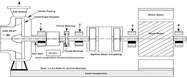
Fig. 2Thrust collar mountings damages and shaft surface frettage wear
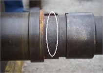
a) Shaft mounting surface frettage
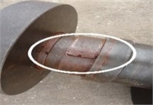
b) Damages in thrust assembly mounting
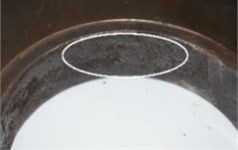
c) Collar contact surface frettage
Table 1Details of Turbomachinery coupled with induction motor
Equipment | Details | Equipment | Details | Equipment | Details |
Design | API 617 | Thrust bearing | Tilting pad | Phases | Three phase |
Compressor type | Single stage centrifugal compressor | Drive Coupling | Spline float as per API 671 | Speed [N] | 50 Hz / 3000 RPM |
Fluid | Sour gas | Lubricant | ISO VG 46 | Rotor bar skew slot angle | 16° |
Suction/discharge pressures (ATA) | 19.77/22.52 | Motor type power rating | Three phase induction motor and 2500 KW | Radial bearings for motor | Plain journal bearings |
Suction/ discharge temperature | 33/46 °C | Rated current | 259 Amps | Foundation type | Rigid foundation |
Compressor radial bearings | Two lobe journal bearing | Voltage rating | 6600 Volts [6.6 kV] | Rotor class and type | Rigid rotor design |
3. Results and discussion
The measured overall vibration velocities (in rms values) on bearing housing surfaces in the vertical, horizontal, and longitudinal directions are given in Table 2. The measured vibration levels for the above turbomachinery exceed the allowable limits according to the standard ISO 10816-3 and ISO 7919-3 for couped industrial machines classification. the allowable vibration velocity for group I machinery with power rating above 300 kW and installed at a rigid support is up to 2.8 mm/s rms, and its exceedance causes damages to the machine [4, 5]. During testing, the allowable shaft vibration depends on a speed according to the standard API 617. For a speed of 3000 rpm, the allowable displacement value is 50.8 µm (peak to peak). The overall vibration is exceeded the allowable values. Hereby, a detailed spectrum analysis was carried out to find the root cause to identify the vibration source. In this regard, Table 3 shows the measured vibration spectrum and peak to peak amplitude at location 3, that means peak-to-peak vibration amplitude is predominant at 1X in all three directions. the measured spectrums at location 3 is only shown in the manuscript for severity, but the same data is available for other locations also. From this, it was observed that motor bearings (3, 4) are demonstrated higher amplitude of vibrations and spectrums with the dominant frequency at a synchronous rotating speed of the motor. Similarly, the longitudinal vibrations at location 3 presented in Table 3 produced in the tune with the vibration amplitude other directions and the thrust force generated in the motor rotor skewed bar and combined static eccentric air-gap effect as discussed in the reference [7, 8].
Table 2Overall vibration measurements on bearing housing stationary surface
Locations | Overall velocity vibrations on bearing surfaces in rms values and its harmonics for two turbomachines (TM1 & TM2) | ||||||
Measurement points | Overall vibration velocity in mm/sec [rms] in three directions | Longitudinal vibration | |||||
Directions | Vertical | Horizontal | Longitudinal | Predominant at rotation speed | |||
Machines | TM1 | TM2 | TM1 | TM 2 | TM1 | TM2 | |
1 | 1.5 | 0.95 | 1.9 | 1.06 | 1.3 | 0.6 | |
2 | 1.4 | 0.75 | 1.8 | 0.85 | 1.4 | 0.6 | |
3 | 3.4 | 1.6 | 4.8 | 1.9 | 4.3 | 2.2 | |
4 | 3.3 | 1.6 | 4.8 | 1.9 | 4.2 | 2.2 | |
Table 3Vibration spectrum at bearing 3 housing surface in three directions
 a) Configuration |  b) Horizontal |  c) Vertical |  d) Longitudinal |
3.1. Longitudinal vibration analysis
Shaft vibration response in the longitudinal direction is measured at thrust collar location using proximity probes during transient runup and steady state operations. the measured spectrums are shown in Table 4. The steady state vibration response peak-to-peak amplitude was present at a synchronous rotation speed and transient run up vibration response spectrum indicating that critical speeds are at 17.5 Hz and 37 Hz.
3.2. Radial vibration analysis
Shaft vibration responses in radial direction under steady state conditions at four bearing locations in two different transverse planes (XX, YY) are measured by using eddy current probes according to ISO standard [3]. Table 5 shows the measured spectrums, dominant frequency, and peak-to-peak displacement amplitude. The measured vibration displacement values are exceed the allowable limit of 43.82 µm. It is also observed that at all four locations, the shaft vibrations peak amplitude is synchronous with rotational speed. Bradford et al [8] discussed that the electrical excitations caused magnetic energy variation in the induction motor due to variation in static air gap eccentricity, which is the root cause for radial and longitudinal dynamic force. These longitudinal vibrations created the micromotion at the thrust collar mounting and frettage wear observations as shown in Fig. 2. The motor nominal air gaps identified as 3.82 millimeter and static air-gap eccentricity measured is vary from 3.41 mm to 4.23 mm as shown in Fig. 4(a). The similar turbomachinery was taken to verify the effect of static air gap eccentricity and the measured static eccentricity variation is from 3.6 mm to 4.04 mm as shown in Fig. 4 (b). The measured overall vibration values for this turbomachinery are within the allowable range as shown in the Table 3 and is demonstrated that less magnetic energy variation reduces the vibration response. Thereby, it is suggested to correct the static eccentric air gaps to obtain uniform values in the motor assembly as shown in Fig. 4(c).
Table 4Shaft longitudinal vibrations at thrust bearing location in µm (Peak to Peak)
 | Shaft longitudinal vibrations in µm (peak to peak) | Frequency and response |
Steady state |  | Response is 51.4 µm at rotational speed (1X) 50 Hz. Overall amplitude is 64.6 µm |
During run up |  | First critical speed is 17.5 Hz and second critical speed is 37 Hz |
Table 5Shaft vibration in horizontal (XX) and vertical (YY) directions at four bearing positions
 | Shaft Vibrations in XX measured Values in µm (peak to peak) | Shaft Vibrations in YY Measured Values in µm (peak to peak) |
Bearing 1 | 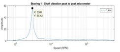 | 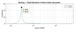 |
At 50 Hz , 55.42 µm (peak to peak) | At 50 Hz , 49.28 µm (peak to peak) | |
Bearing 2 |  |  |
At 50 Hz , 55.31 µm (peak to peak) | At 50 Hz , 48.93 µm (peak to peak) | |
Bearing 3 |  |  |
At 50 Hz , 102.7µm (peak to peak) | At 50 Hz , 63.32 µm (peak to peak) | |
Bearing 4 |  |  |
At 50 Hz, 102.4 µm (peak to peak) | At 50 Hz , 63.28 µm (peak to peak) | |
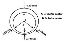 | 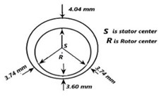 | 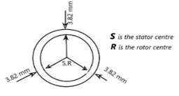 |
Fig. (4a) induction motor1 air gap diagram at 120 degrees measurements | Fig. (4b) induction motor 2 air gap diagram at 120 degrees measurements | Fig. (4c) induction motors with uniform airgap diagram at 120 degrees measurements |
4. Conclusions
The present paper has discussed the vibration diagnosis of thrust collar failure in a turbomachinery coupled with induction motor. The measured overall vibration values at bearing locations are compared with ISO limits and found the allowable values exceeded at the motor bearing locations. The detailed spectrum analysis and shaft displacement measurement showed the dominant vibrations in the longitudinal and radial directions at a rotational speed. Vibration analysis indicates these vibrations are occur due to static eccentric air gaps with inadequately equalised magnetic pull and are synchronized with the speed. These excessive longitudinal vibrations cause thrust bearing assembly damages and amplified radial vibrations as a result of static air gaps with unbalance magnetic pull. The present study focussed on understanding the effect of longitudinal vibrations and inferred with static air-gap eccentricity variation in the turbomachinery coupled with induction motor and obtained the minimum vibration levels by correcting static air-gap variation to uniform values for improving machinery availability.
References
-
API 617. Centrifugal Compressors for General Refinery Service. API Publication, 1988.
-
API 684. Introduction to Lateral Critical and Torsional Analysis and Rotor Balancing. First edition, API Publication, 1996.
-
ISO 13373 -1(2). Condition Monitoring and Diagnosis of Machines Vibration Condition Monitoring, Part 1 General Procedures, and Part 2 Processing and Presentation of Vibration Data. Indian Standard Published in Part 1-For Year 2002 and Part 2 for 2005.
-
ISO 10816 -3 (VDI-2056-3). Mechanical Vibration -Evaluation of Machine Vibration by Measurements on Non-Rotating Parts -Part 3: Industrial Machines with Nominal Power Above 15 Kw and Nominal Speeds Between 120 r/min and 15 000 r/min When Measured in Situ. ISO Publication, 2009.
-
ISO 7919-3. Mechanical Vibrations on Evaluation of Machine Vibrations on Shaft Vibrations for Coupled Industrial Machines. ISO Publication, 2008.
-
Thomson W. T., Gilmore Ronald Motor current signature analysis in induction motor drives. Proceedings of 32nd Turbomachinery Symposium, Texas Huston USA, 2003, p. 145-156.
-
Shekhawat Narendra M. Comprehensive analysis rotor eccentric faults in squirrel cage induction motor. International Journal of Scientific Research and Development, Vol. 7, Issue 3, 2019, p. 1659-1666.
-
Bradford C. E., Rhudy R. G. Axial magnetic forces on induction-motor rotors. Journal of AIEE Transactions, Vol. 72, 1953, p. 488-492.
