Abstract
In this paper, the vibration characteristic of the casing under rub-impact condition is analyzed by using finite element method, envelope demodulation and empirical mode decomposition. Firstly, aiming at the structure characteristics of the casing of the rotor system, the finite element model is established by ANSYS software. Modal analysis and transient analysis are carried out in detail. The first six order natural frequencies and corresponding vibration modes are acquired in the mode analysis. The transient response history and time-amplitude curves are obtained in the harmonic response analysis. The vibration characteristics and rule of the casing under rub-impact condition are also presented in the transient dynamic analysis. Secondly, the vibration mechanism analysis of the casing is performed. Since the pulse force due to rubbing fault may lead to casing’s resonance, the envelope demodulation method and empirical mode decomposition (EMD) are utilized to diagnose the rubbing fault. By means of the envelope demodulation and EMD, the stator’s vibration signal is analyzed, and the rub-impact fault diagnosis is fulfilled. Finally, as for the aero-engine, the vibration signal obtained is just the acceleration on casing, and it is of great difficulty to obtain the vibration displacement. Hence, experiment of one-point rub-impact is conducted, and the validity and feasibility of the method adopted are verified by the testing response data. Besides, the casing vibration acceleration signals are analyzed in order to extract the rubbing fault’s features. Results demonstrate that the casing resonance envelope signal is very suitable for detecting the rub-impact fault. It is worth relying that envelope demodulation method and EMD would have a promising application for the rubbing fault diagnosis between the rotor and the casing.
1. Introduction
Occurrence of rubbing fault between rotor and stator may result in rotating machines failure or reduce these equipment performance, which will lead to the increase of maintenance cost and even catastrophic accidents. Therefore, it’s important to recognize and diagnose the existence and severity of rubbing fault precisely in rotating machines when running. Early diagnosis of rubbing fault in rotating machinery can effectively decrease the maintenance expense and guarantee safer and longer lasting operation of the machine to some extent. Hence, the analysis of rotor system rubbing mechanism, extraction of fault characteristics and diagnosis of rubbing fault have been the main task of the rotor dynamics research.
In recent years, many scholars have done a lot of research work about rubbing fault of rotating machinery, mainly concentrated on the rotor vibration signal processing. Spectrum characteristics analysis has been widely applied in the rubbing fault diagnosis, which plays a major role in providing some characteristics as indicators of faults [1-3]. In addition, some advanced methods of signal processing such as wavelet transforms (WT) [4-6], cepstral analysis [7, 8], blind source separation (BSS) [9] and so on have also made remarkable achievements in detecting rub-impact.
However, diagnosis of rubbing fault is the challenging topic as many features of rub-impact are the same as the other common faults such as unbalance [10]. These similar signatures may cause false diagnosis. Meanwhile, for large-scale power machinery, such as gas turbine and aero-engine, vibration signal measured is just the acceleration signal collected from casing, it’s of great difficulty to acquire the vibration displacement signal because of its own structural features. Besides, the casing is also typical thin-walled structure.
All of the aforementioned characteristics are not taken into account in the existing theoretical and experimental researches, so they can’t be directly used to aero-engine rubbing fault detection. Hence, it is very significant and essential to study the vibration characteristics of casing and laws of casing vibration acceleration signals for effectively identifying the rubbing faults of aero-engine.
In view of this, another important role, the vibration acceleration of casing, is used as the information source of diagnosis in this paper. Firstly, the characteristics and laws of rubbing fault are researched by using finite element method, in which a contact model is built. Secondly, the casing vibration acceleration signals under rub-impact status are collected, and the rubbing fault information of the rotor and the casing can be obtained efficiently by means of envelope modulation technique and empirical mode decomposition (EMD). The experimental results are used to verify the dynamic response obtained by using finite element method. The rub-impact characteristics extracted in the paper can be useful in identifying the rubbing fault of rotating machine, especially for aero-engine.
2. Finite element modeling and dynamic analysis of casing
Because of the coupling system complexity of the rotor and the casing, it is difficult to establish a mathematical model. From this perspective, using the theoretical vibration dynamic to do the analysis is suitable. Finite element method (FEM) are widely adopted to deal with the problem of mechanical vibration. The method could achieve higher numerical stability, but will consume more computer storage space. FEM is used to solve rotor dynamic problems until 1970s. With the rapid development of computer science, the FEM method has become more and more popular in analyzing mechanical vibration problems. Therefore, FEM is applied to complete geometric modeling, dynamic simulation and vibration analysis of casing.
2.1. Modal analysis
Since the rub-impact occurred between the blade and the casing can lead to the unsteady motion of the blade and even arose the high frequency vibration modes of casing, it is significant to conduct the modal analysis of casing. For achieving the finite element analysis about the casing, meshes are created utilizing the ANSYS software. Finite element meshing of the casing surface and the pedestal are done with three-dimensional, 8-node tetrahedral structural solid elements (SOLID 185).
Casing material is considered with the isotropic elasticity. The casing material properties are assigned as follows.
Young’s Modulus: 2.09×10⁵ MPa;
Poisson’s ratio: 0.269; Density:7890 kg/m3.
Boundary condition of meshed model are assigned as all nodes of the whole pedestals’ bottoms are fixed and the contact surfaces between the casing and the pedestals are bonded, and there are a total of 41533 elements, as shown in Fig. 1.
After assigning both bottom faces of the pedestal and casing material properties for the analysis, the calculation has been done through FE based model analysis solver of ANSYS.
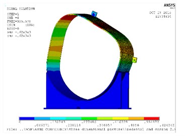
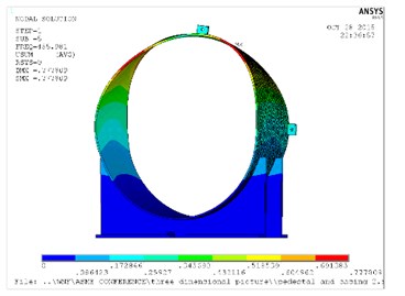
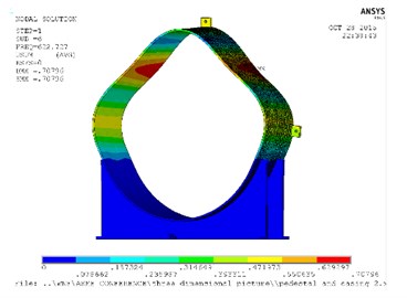
The following natural frequencies and mode shapes obtained from the FEM analysis are shown in Table 1 and Fig. 2, respectively. Only the first six orders frequencies are extracted in this paper, since the vibration amplitude of the high frequency is relatively small.
Fig. 1Finite element mesh chart of casing and pedestal
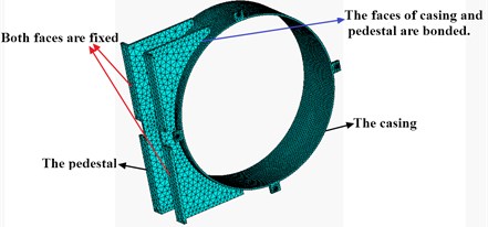
Table 1Frequencies (Hz)
Orders | 1 | 2 | 3 | 4 | 5 | 6 |
Frequency | 88.296 | 173.95 | 121.19 | 395.58 | 455.98 | 622.73 |
Fig. 2Natural frequency and mode shapes for casing and pedestal
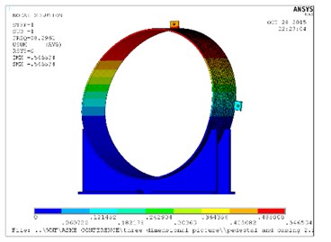
a) Mode 1
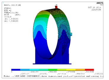
b) Mode 2
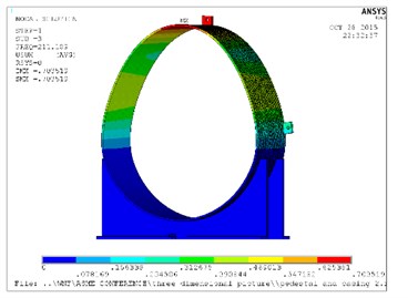
c) Mode 3
d) Mode 4
e) Mode 5
f) Mode 6
2.2. The establishment of the contact force model
In the section, we fully consider that elastically deformable radial blades of outer radius ‘R’, are installed on a rigid disk of hub radius ‘r’, as illustrated in Fig. 3. The casing interaction forces upon the blade tip is acquired by means of Coulomb friction model. Based on the experimental conditions, it is supposed that the rub-impact only occurs in the radial direction. The individual blades behave like a cantilever beam-column of span length ‘L’ and are subjected to a centripetal force field generated due to the rotor spin velocity ‘ω’ with the blade tip rub load F (+sign: tension and – sign: compression) acting along the beam axis. The tip rub force F denotes a dynamic contact load, which is non-zero only under rub-impact status and will always have a (−) sign because of the contact load being compressive in nature. Let μ denotes the friction coefficient.
Fig. 3Rub forces F and μF on the rotor blade
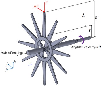
Fig. 4Schematic view of the rub zone on the casing
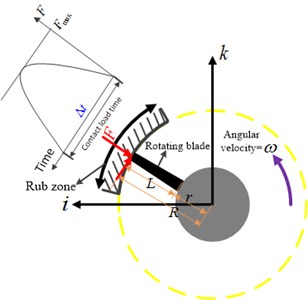
Pulse loads [11-16] refer to forces that are applied over a short amount of time, less than 100 ms or so. Although that seems like a very short time window, it can easily represent 30 or more revolutions in some rotating machines, certainly long enough to include an entire rub event. The stationary global Cartesian unit vectors (i,j,k) is used to describe the position of the blades. The parameter ∆t is defined as the time width in time, as shown in Fig. 4. The backward whirl induced by dry friction is ignored because the rotating speed is relative small and the casing is typical thin-walled structure. It is assumed that every blade has the same physical and geometric parameters, and rubbing occurs in the same position, the pulse force can be expressed as:
where A denotes the amplitude of pulse force, n is the number of blade, ω represents the angular velocity of rotor.
The finite element method (FEM) is chosen to perform the time-accurate or transient analysis because it includes an explicit based solver that is suitable for short-duration loading events such as impacts.
2.3. Transient dynamics analysis of casing
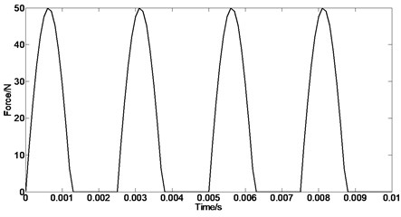
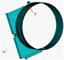
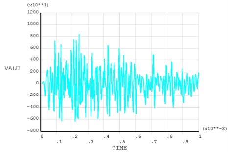
Transient dynamics analysis is used to identify the structure dynamic characteristics in response of the load changing over time. The same boundary condition is adopted when the transient dynamic analysis is carried out. Periodic very short pulse force will be imposed on the casing when the rubbing fault occurs between the rotor and the casing. According to the experiment conditions, the amplitude of rubbing force acting on inner surface of the casing is set to 50 N and the rubbing cycle is defined to 0.0025 s, as shown in the left side of Fig. 5. The number of node which the rubbing force is imposed on is 11045, as shown in the right side of Fig. 5. The 11045th node’s Y-component of vibration acceleration response shown in Fig. 6 is obtained by using ANSYS to solve.
It can be seen from Fig. 6 that pulse rubbing force generated by rubbing can arose the casing’s high-frequency inherent vibration mode, which is taken as the carrier. The amplitude of carrier is subjected to periodic rubbing pulse modulation, so the casing vibration mode shows complex amplitude modulation phenomenon. Meanwhile, the contact and separation process often generated impacts between the rotor and casing. Therefore, the dynamic response of casing under rubbing have obvious impact characteristics. It can be observed from Fig. 6 that the amplitudes under rub-impact condition roughly present a downward trend, which is due to the attenuated vibration of corresponding node on casing in the short time after rub-impact. In order to extract the rub-impact feature, further investigate the amplitude-modulated and amplitude variation characteristics, it is essential to carry out the blade-casing rubbing experiments and collect the vibration acceleration signals from the casing.
Fig. 5a) Periodic rubbing force; b) force diagram of the casing
a)
b)
Fig. 6Y-component of vibration acceleration response
3. Experimental verification
3.1. Experiment arrangement of the rotor system
In order to find out the laws of blade-casing rubbing fault, a simplified rotor-bearing-casing test bed system is carried out for the sake of simulating the rubbing fault. The schematic of the rotor-bearing-casing test bed is shown in Fig. 7. The picture of the rotor-bearing-casing test rig and the sketch of data acquisition system are illustrated in Fig. 8(a) and 8(b), respectively. The framework of the rotor-bearing-casing system are composed of a casing, one disk mounted on a shaft, and the shaft is supported by double row angular contact ball bearing. A motor drives the shaft to rotate by a flexible coupling.
Fig. 7Schematic of the rotor-bearing-casing test bed

The rotor-bearing-casing system is driven by the motor with the speed of 2100 rpm. The radial rubbing status is simulated by adopting a rub screw to hit the blade tip. The vibration acceleration signals of casing are measured by the acceleration sensors. An eddy current sensor is used to obtain the rotational speed by monitoring the key phase. The data acquisition system is utilized to capture the time series. The sampling frequency of the data acquisition device is set to be 4 kHz.
Fig. 8Experiment setup of rotor-bearing-casing system
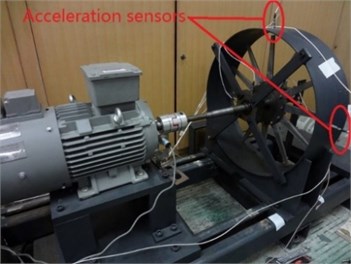
a) Test rig for rubbing between the blade and casing
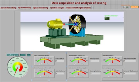
b) Data acquisition software and test rig monitoring interface
4. Time-frequency features of casing with rub-impact fault
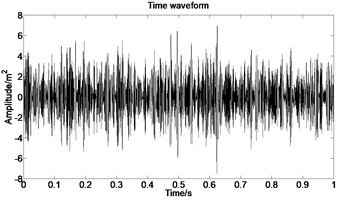
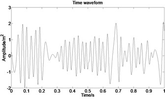
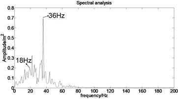
To further study the mechanism of rubbing fault, the experiment in which rubbing fault occurs in one fixed position is conducted. The testing data of channel 2 (CH2) acquired from the experiments is selected; the corresponding rubbing position is horizontal side; and the experimental rotating speed is 2100 rpm = 35 Hz. Fig. 9 shows the vibration acceleration time waveforms of casing.
Fig. 9Waveform
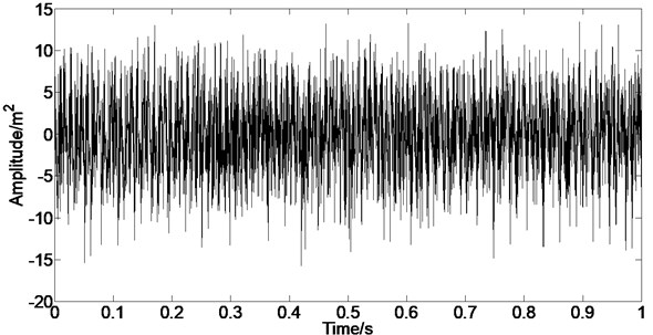
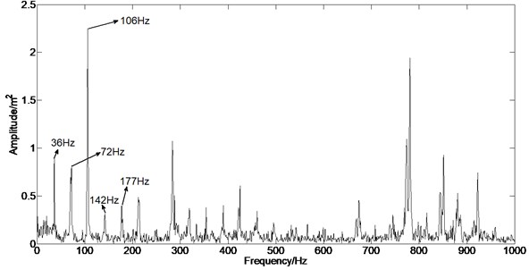
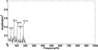
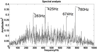
Fig. 10 shows the FFT spectrum of the casing vibration with rubbing fault. The fundamental frequency 1X, second harmonic component 2X and higher frequency components can be clearly observed, which is in accordance with results in [17-19]. Nevertheless, the rubbing fault signals with amplitude modulation features are always mixed in the background and noise signals. Hence, in order to better observe fault features, envelope demodulation method and empirical mode decomposition are adopted to analyze the rub-impact acceleration signal picked up from the casing.
Fig. 10Spectrum
4.1. Extraction of signal envelopes
A large amount of variation component in signals could be embodied in the envelopes of signals, and the carrier wave of envelopes is usually taken by the high-frequency components of vibration signal. Hilbert technique is an effective tool to obtain the envelopes of signals in fault diagnosis [20, 21].
As for a real signal x(t), H{x(t)} represents the Hilbert transform of x(t), which is defined using the Cauchy principal value (denoted by P) as:
The analytic signal g(t) of the real signal can be obtained which is defined as:
where ˆx(t) denotes Hilbert transform of the real signal x(t), and the amplitude of analytic signalis expressed as:
This is the envelope of x(t).
4.2. The application of envelope demodulation method to the rubbing fault diagnosis of the rotor and the casing
Based on the basic characteristics of the casing vibration signal caused by rubbing, the envelope demodulation method is utilized to separate the high frequency inherent vibration signal of the casing. Specific procedures are shown in Fig. 11.
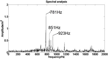
The envelope analysis results of original casing acceleration signal are shown in Fig. 12, respectively. It can be found that the rubbing fault information can be extracted from the strong interference signal, such as background signal and noise signal, when the envelope analysis of the original signal under rub-impact status is carried out.
Fig. 11Specific procedures
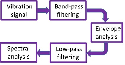
Fig. 12Envelope analysis of casing signal under rubbing
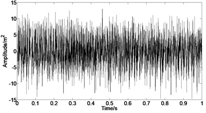
a) Time domain after bandpass filter
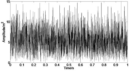
b) Envelope of time domain
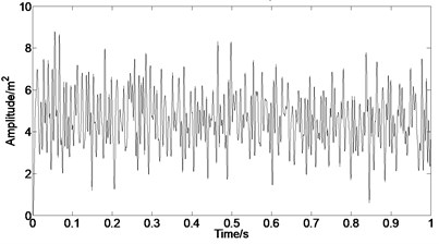
c) Time domain after low-pass filter
d) Spectral analysis after filtering
4.3. Rubbing features extraction based on EMD
As aforementioned, the responses of the system present nonlinear phenomenon and some faults almost have similar frequency characteristics, which to some extent increases the complexity of fault detect just depend on tradition features. Thus, the method of empirical mode decomposition (EMD) is applied to further process the nonstationary and nonlinear vibration acceleration signals and excavate more fault information that cannot be detected just relying on statistical parameters in time domain and frequency domain. The novel tool, EMD, first developed for data analysis by Huang et al [22], is a kind of adaptive and unconstrained decomposition of the complex signal into a finite number of almost orthogonal intrinsic mode functions (IMFs) following a recursive process and has been widely used for various applications [23-26]. An IMF is supposed to satisfy the following two conditions:
1) In the whole data set, the number of extrema and the number of zero crossings should be equal or different no more than one.
2) At any point, the mean value of the envelope defined by the local minima and local maxima is zero.
Sifting is implemented iteratively for extracting IMFs from original signal using following algorithm:
1. Let m1 represent the mean of upper and lower envelope value of original signal x(t), which are determined from a cubic-spline interpolation of local maxima and minima. The first component, h1(t) is calculated as shown in Eq. (5):
2. In next step, h1(t) is considered as the original signal, and m11 is the mean of upper and lower envelope value of h1(t) and h11(t) is obtained:
3. Above procedure is repeated n times, until h1n conforms to the conditions of an IMF. Then it is designated as first IMF, c1(t)=h1n(t), it is then separated from rest of the data Eq. (7):
4. Now r1(t) is considered as main signal and steps 1-3 are repeated for calculating second IMF.
5. The number of IMFs that can be extracted depends on the original signal. The stopping criterion is that the rm(t) becomes monotonic function from which no more IMF can be extracted.
Therefore, based on the definition of EMD approach, any complicated signal could be theoretical expressed as:
where ck(t) denotes the kth IMF of the original signal x(t) and rm(t) represents the ultimate residue value, which could be the signal mean trend or a constant. On account of the two conditions of each IMF as mentioned above, the IMF may be a single component of frequency-modulated (FM) or amplitude-modulated (AM) signal.
The acceleration signal shown in Fig. 9 is also used in the section. EMD is used to decompose the original signal and the result is presented in Fig. 13. The x axis signifies the time and the y represents amplitude in Fig. 14.
Fig. 13IMFs obtained by using EMD
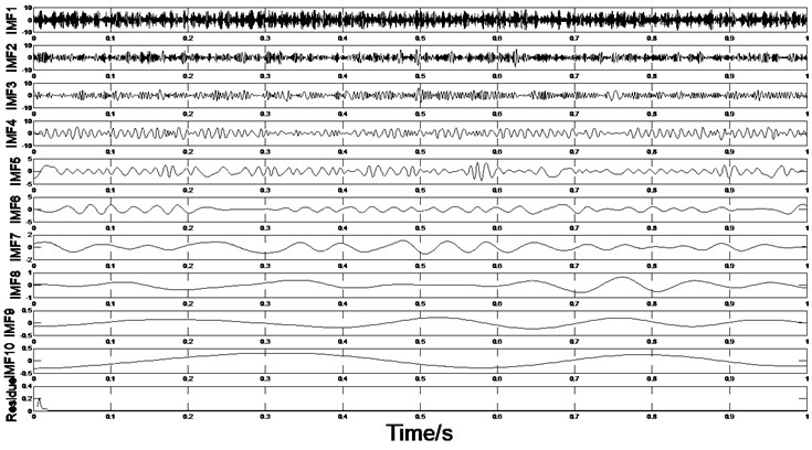
Fig. 14The first six order IMFs of acceleration signal decomposed by EMD and their corresponding spectrums
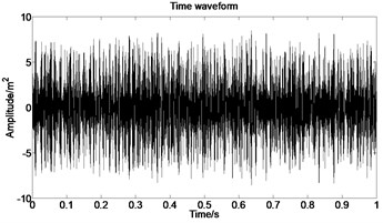
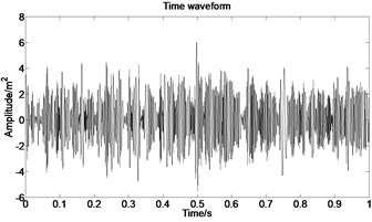
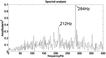
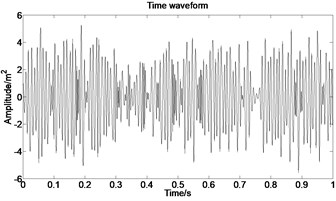
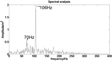
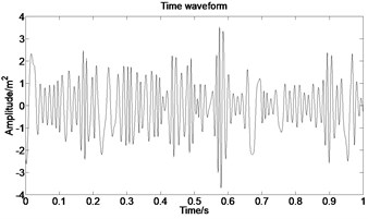
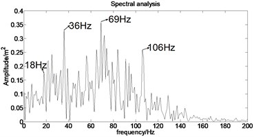
It can be observed from Fig. 14 that the complicated acceleration vibration data is effectively decomposed into ten IMFs and residue, which reflect the information of different frequency bands. It should be noted from Fig. 14 that the first IMF1 contains the amplitude-modulated features, which is generated due to the periodic rub-impact occurred between the rotor and the casing. Furthermore, Fig. 14 also clearly shows that there exist the 1/2×, 1×, and some sup-× components etc. in the spectrum. These components are identified as the indicators of rub-impact in most cases, in other words, rubbing fault could be detected with EMD. The EMD approach successfully extracts all the mentioned signatures once more. This application, thus further demonstrates the validity of EMD in diagnosing rubbing fault.
In order to verify the effectiveness, some comparisons are performed. In the past, cepstral analysis has been applied in the rotating machinery condition monitoring since it can extract excitation information from the vibration signal [3, 7]. However, when the cepstral is employed to rotor vibration signals analysis, the impulse response function and the excitation should meet certain conditions, which the rotor vibration signals may not satisfy [27]. Wavelet owns the variable time-frequency window and could decompose a complicated signal into a number of components, which enable wavelet analysis to distinguish the rub-impact component from the rotor system vibration signal [6, 28]. However, wavelet analysis is necessarily an adjustable window Fourier transformation. Due to the limited length of wavelet base function, energy leakage will happen in wavelet transformation of signal. Furthermore, once wavelet base function and decomposition scales were confirmed, the result of wavelet transform would be the signal under a fixed scale, whose frequency components relate only to the sampling frequency of original signal and have no relation to the original signal itself. A demodulation method on the basis of the local mean decomposition (LMD) was proposed for rub-impact fault diagnosis [29], which can extract the transient fluctuations of the instantaneous frequency of the fundamental harmonic component. However, it should be noted that using LMD, the mode mixing problem cannot be solved.
5. Conclusions
The finite element model of casing is established and characteristics analysis of acceleration vibration signal under rubbing fault is carried out. The acceleration vibration signals contain abundant information, and the rubbing fault signal will present amplitude modulation characteristics due to the periodic rub-impact effect occurred between the rotor and the casing.
By employing EMD method to interpret the rubbing vibration acceleration signal, the rub-impact signal, noise signal and strong background signal could be separated and the amplitude modulation information of the rotor-bearing-casing system can be extracted effectively. Besides, the EMD approach has a higher algorithm efficiency, and it allows observation of longer term transient casing vibration. It is helpful for improving the reliability of machine condition assessment and diagnosis.
It is shown that the proposed methods provide reliable and potential ways to diagnose the casing vibration, by which means the rotary machine condition could be diagnosed accurately.
References
-
Shi D. F., Wang W. J., Unsworth P. J., et al. Purification and feature extraction of shaft orbits for diagnosing large rotating machinery. Journal of Sound and Vibration, Vol. 279, 2005, p. 581-600.
-
Dang Xiangyi Experimental Investigation and Signal Features Extraction of Casing Vibration Faults. Tsinghua University, 2014.
-
Chen G. Study on the recognition of aero-engine blade-casing rubbing fault based on the casing vibration acceleration. Measurement, Vol. 65, 2015, p. 71-80.
-
Al-Badour F., Sunar M., Cheded L. Vibration analysis of rotating machinery using time-frequency analysis and wavelet techniques. Mechanical Systems and Signal Processing, Vol. 25, Issue 6, 2011, p. 2083-2101.
-
Ocak H., Loparo K. A., Discenzo F. M. Online tracking of bearing wear using wavelet packet decomposition and probabilistic modeling: a method for bearing prognostics. Journal of Sound and Vibration, Vol. 302, Issues 4-5, 2007, p. 951-961.
-
Peng Z., He Y., Lu Q., et al. Feature extraction of the rub-impact rotor system by means of wavelet analysis. Journal of Sound and Vibration, Vol. 259, Issue 4, 2003, p. 1000-1010.
-
McCarthy D. J., Lyon R. H. Recovery of impact signatures in machine structures. Mechanical Systems and Signal Processing, Vol. 9, Issue 5, 1995, p. 465-483.
-
Zheng G. T., Wang W. J. A new cepstral analysis procedure of recovering excitations for transient components of vibration signals and applications to rotating machinery condition monitoring. Journal of Vibration and Acoustics, Vol. 123, Issue 2, 2001, p. 222-229.
-
Jing J. P., Meng G. A novel method for multi-fault diagnosis of rotor system. Mechanism and Machine Theory, Vol. 44, Issue 4, 2009, p. 697-709.
-
Sun Y. L., Zhang Y. X., Chang H. B. Method of rotor rub-impact faults diagnosis based on stator vibration signal. Journal of Vibration Engineering, Vol. 22, Issue 4, 2009, p. 391-394.
-
Turner K., Adams M., Dunn M. Simulation of engine blade tip-rub induced vibration. ASME Turbo Expo 2005: Power for Land, Sea, and Air, American Society of Mechanical Engineers, 2005, p. 391-396.
-
Sinha S. K. Non-linear dynamic response of a rotating radial Timoshenko beam with periodic pulse loading at the free-end. International Journal of Non-Linear Mechanics, Vol. 40, Issue 1, 2005, p. 113-149.
-
Kou H., Yuan H. Rub-induced non-linear vibrations of a rotating large deflection plate. International Journal of Non-Linear Mechanics, Vol. 58, Issue 1, 2014, p. 283-294.
-
Padova C., Dunn M. G., Barton J., et al. Casing treatment and blade tip configuration effects on controlled gas turbine blade tip/shroud rubs at engine conditions. Journal of Turbomachinery, Vol. 133, Issue 1, 2008, p. 261-276.
-
Ma H., Tai X., Han Q., et al. A revised model for rubbing between rotating blade and elastic casing. Journal of Sound and Vibration, Vol. 337, Issue 337, 2015, p. 301-320.
-
Cao Dengqing, Yang Yang, Chen Huatao, et al. A novel contact force model for the impact analysis of structures with coating and its experimental verification. Mechanical System and Signal Processing, Vol. 70, Issue 71, 2016, p. 1056-1072.
-
Mayes I. W., Davies W. G. R. The vibrational behavior of a rotating shaft system containing a transverse crack. I Mech E Conference Publication, Vibration in Rotating Machinery, 1976, p. C168/76.
-
Gasch R. Dynamic behavior of a simple rotor with across-sectional-rack. I Mech E Conference Publication, Vibration in Rotating Machinery, 1976, p. C178/76.
-
Mayes I. W., Davies W. G. R. A method of calculating the vibrational behavior of coupled rotating shaft containing a transverse crack. I Mech E Conference Publication, Vibration in Rotating Machinery, 1980, p. C254/80.
-
De Chanvalon, Manon T. Quantum symmetry groups of Hilbert modules equipped with orthogonal filtrations. Journal of Functional Analysis, Vol. 266, Issue 5, 2014, p. 3208-3235.
-
Jordão T., Menegatto V. A. Weighted Fourier-Laplace transforms in reproducing kernel Hilbert spaces on the sphere. Journal of Mathematical Analysis and Applications, Vol. 411, Issue 2, 2014, p. 732-741.
-
Huang N. E., Shen Z., Long S. R., et al. The empirical mode decomposition and the Hilbert spectrum for nonlinear and non-stationary time series analysis. Royal Society of London Proceedings, Vol. 454, Issue 1971, 1998, p. 903-995.
-
Cheng J., Yu D., Tang J., et al. Local rub-impact fault diagnosis of the rotor systems based on EMD. Mechanism and Machine Theory, Vol. 44, Issue 4, 2009, p. 784-791.
-
Yang W., Tavner P. J. Empirical mode decomposition, an adaptive approach for interpreting shaft vibratory signals of large rotating machinery. Journal of Sound and Vibration, Vol. 321, Issue 3, 2009, p. 1144-1170.
-
Liu M. L., Wang K. Q., Sun L. J., et al. Applying empirical mode decomposition (EMD) and entropy to diagnose circuit breaker faults. Optik, Vol. 126, 2015, p. 2338-2342.
-
Lin L., Chu F. HHT-based AE characteristics of natural fatigue cracks in rotating shafts. Mechanical Systems and Signal Processing, Vol. 26, 2012, p. 181-189.
-
Zheng G. T., Wang W. J. A new cepstral analysis procedure of recovering excitations for transient components of vibration signals and applications to rotating machinery condition monitoring. Journal of Vibration and Acoustics, Vol. 123, Issue 2, 2001, p. 222-229.
-
Peng Z. K., Chu F. L., Tse P. W. Detection of the rubbing-caused impacts for rotor-stator fault diagnosis using reassigned scalogram. Mechanical Systems and Signal Processing, Vol. 19, Issue 2, 2005, p. 391-409.
-
Wang Y., He Z., Zi Y. A demodulation method based on improved local mean decomposition and its application in rub-impact fault diagnosis. Measurement Science and Technology, Vol. 20, Issue 2, 2009, p. 28-28.
Cited by
About this article
The research work is supported by the National Natural Science Foundations of China (No. 11572167). The authors are also grateful to the anonymous reviewers for their worthy comments.

