Abstract
The seismic performance evaluation and retrofit process are very important in damaged bridges. If the result is not appropriate, then retrofit process are required. In this paper, to validate the seismic performance of retrofitted bridge experimentally, an experimental study was conducted to verify the application and efficiency of the jacket retrofit method to ensure seismic performance of damaged reinforcement concrete (RC) bridge piers. A total of 4 RC bridge piers was made and then 3 piers were pre-loaded under the range of service load to be damaged. These piers were retrofitted and repaired using a carbon fiber reinforced polymer (CFRP), steel plate, and fiber steel composite (FSC) plates. These retrofitted and repaired piers were subjected to monotonic loading. Hysteresis and ultimate behaviors of the 3 RC piers were evaluated and compared with those of 1 non-damaged pier (standard specimen). As a test result, the retrofitted and repaired RC bridge piers applied by the jacket retrofit method were ensured under the targeted displacement ductility and ultimate load. The ultimate load and displacement ductility of the pier retrofitted and repaired by FSC plate were higher than those of other piers by CFRP and steel plates and also the pier by FSC plate showed better energy dissipation capacity than others. Generally, RC bridge pier retrofitted and repaired with the jacket retrofit method has low ductility but it was found that the pier retrofitted and repaired by FSC plate combined with CFRP and steel wire had overcome effectively this disadvantage through ductility evaluation based on the concept of energy numerically. This experiment showed that one could improve the safety margin and targeted ductility by repairing the cracks, spalls, etc. of the damaged RC bridge piers appropriately and then retrofitting them with the high ductile materials. The responses of existing damage bridges are compared with those of retrofitted bridge by jacket method for earthquake of target level, and also seismic performances are evaluated. By the test and analysis results it can be concluded that the proposed seismic retrofit method was found to be valid.
1. Introduction
Most of existing bridges already display developed agedness and their seismic performance in case of potential earthquakes are being questioned. An earthquake can make the member of the bridge damaged. In case of large damage, it can lead the collapse of the bridge. The bridge that can be damaged during earthquakes should be secured of required seismic performance. First, proper seismic performance evaluation should be executed in order to ensure seismic performance. If serious damage is expected as a result of evaluation, it is required to retrofit the bridge. Currently, a wide variety of methods has been proposed for a seismic retrofit [1-3]. The study on the one of these seismic retrofit methods repairing and retrofitting damaged major members such as concrete slabs and girders by using composite materials such as Fiber Reinforced Polymer (FRP) and steel plate has been extensively done [4-7]. For Reinforcement Concrete (RC) piers in particular, the simple and effective method retrofitting the RC piers by covering with the steel plate or FRP externally has been suggested. The retrofit of RC piers with steel plate was first proposed by Sun et al. [8], since then study on this method has been continuously done by Preistley et al [9]. In addition, the study on applying FRP plate instead of steel plate to increase ductility and strength of piers has been done by Matsuda et al. [10], Xiao et al. [11] and etc. [12, 13].
However, there is a disadvantage that brittle failure of the structure occurs if the damaged structural members are retrofitted by the FRP jacket generally because retrofit FRP material is brittle and interface failure occurs at the bonding surface. In recent years, in order to enhance these shortcomings, Fiber Steel Composite (FSC) plate combined with FRP and steel wires has been developed. Thus, in this paper, the application and efficiency of jacket retrofit method were experimentally verified to obtain seismic performance of the damaged RC piers. This study was carried out by following steps. A total of 4 RC piers with same reinforcement ratio were made. The behavior of one RC pier (standard specimen) was evaluated under the repeated monotonic increasing loading, a quasi-static test. The other 3 RC bridge priers were pre-loaded under the initial yielding force measured by the quasi-static test of the standard specimen to be damaged. The cracks of 3 damaged piers were repaired by injecting epoxy and then were retrofitted by using FSC plate, Carbon Fiber Reinforced Polymer (CFRP), and steel plate. The hysteretic behavior of each repaired and retrofitted specimen under the cyclic loading was evaluated respectively. Maximum force and maximum displacement of 3 piers were compared with those of standard specimen. The responses of existing damage bridges are compared with those of retrofitted bridge by jacket method for earthquake of target level, and also seismic performances are evaluated.
2. Experimental program
2.1. Specimen production
A total of 4 RC piers was made in order to compare seismic retrofit performance experimentally. Standard specimen, specimen retrofitted by CFRP, specimen retrofitted by FSC plate, and specimen retrofitted by steel plate were made and the behaviors of each specimen were evaluated respectively.
Fig. 1Cross section of specimen (unit: mm)
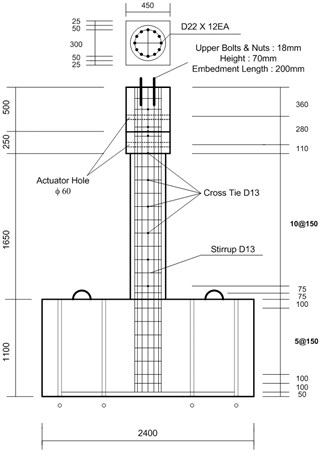
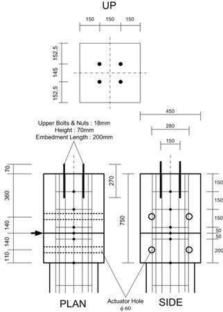
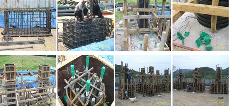
In order to compare performance between standard specimen and retrofit specimens, the detail arrangement of reinforcement and section of the specimens were made identically. Though specimens were circular in cross section, foundation and coping of the specimens had different cross sections because the foundation should have greater stiffness than the pier to be fully fixed and the section of the coping should be determined by considering shape and size of the actuator. The 28 days concrete compressive strength (f28) was in the 24 MPa. Pouring the concrete into the specimens was done at the foundation first and then done at the pier. Strain gauges were attached to the main and stirrup reinforcement to measure the strain of reinforcement before pouring concrete. Main reinforcement was D22 (Diameter of 22 mm), hoop reinforcement and cross-tie were D13 (Diameter of 13 mm). As using that reinforcement, the problems about geometric and material similarities that might arise because of a small-scale model was excluded as much as possible. The material properties of the specimen are provided in Table 1. The cross section of specimen is shown in Fig. 1 and the making of the specimens are shown in Fig. 2.
Table 1Material properties of specimens (unit: MPa)
Concrete | Steel reinforcement | ||
Compressive strength | 27 | Yield strength | 423 |
Elastic modulus | 21,700 | Tensile strength | 600 |
Fig. 2The making of specimens
2.2. The process of test and measurement detail
By using an actuator with built in a load cell and a displacement cell, loads and displacement of the specimens were measured. Flexural failure was expected because aspect ratio was 4.13 as 1650 mm in the height and 400 mm in the diameter of the pier. Thus, plastic hinge could be occurred mostly at the bottom of the pier, so strain gauges were attached to the bottom of the pier. For the quasi-static test, the axial force corresponding to 0.15×f28×concrete section (Ag) was constantly loaded using an oil jack. And the lateral force was loaded as a displacement control method using hydraulic actuator with capacity of 500 kN. The lateral load was loaded repeatedly as 3 cycles up to the yield displacement (Δy) obtained from the experiment. Installation locations of the gauges and a range of loading for quasi-static test are shown in Fig. 3.
2.3. Pre-loading and retrofit process
Except for the standard specimen, the other 3 RC bridge priers were pre-loaded under the initial yielding force measured by the quasi-static test of the standard specimen to be damaged in advance and then were retrofitted by using FSC plate, CFRP, and steel plate after repair of crack by injecting epoxy. The result of the pre-loading test is shown in Fig. 4.
The amount of retrofit for each method was determined to make the same strength. The material properties of CFRP, steel plate and FSC plate are provided in Table 2. And the mechanical behavior of CFRP, steel plate and FSC plate are provided Fig. 5. The process of repair and retrofit is shown in Fig. 6.
Fig. 3Measurement detail and loading range for quasi-static test
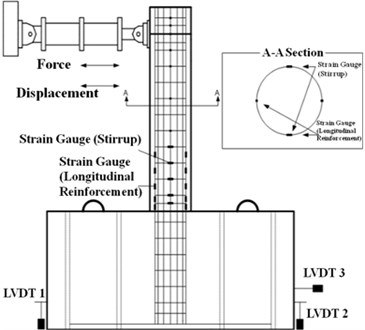
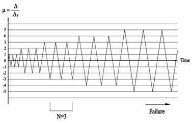
Fig. 4The result of the pre-loading test
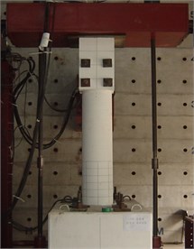
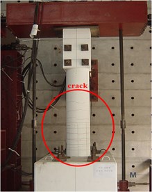
Table 2Material properties of CFRP, steel plate and FSC plate
Retrofit material | Tensile strength, MPa | Elastic modulus, MPa |
CFRP | 3,55 | 2.35×10⁵ |
Steel plate | 320 | 2.00×10⁵ |
FSC Plate | 2 | 2.15×10⁵ |
Fig. 5Mechanical behavior of CFRP, steel plate and FSC plate
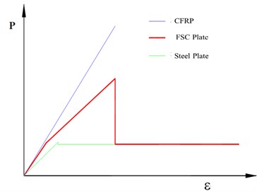
Fig. 6Repair and retrofit of the damaged specimen by pre-loading
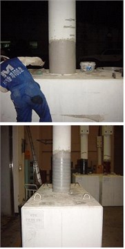
a) FSC plate retrofit
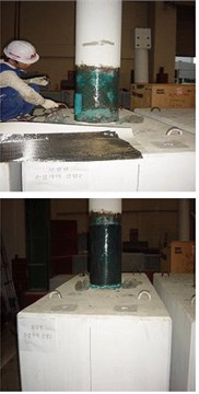
b) CFRP retrofit
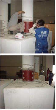
c) Steel plate retrofit
3. Test results
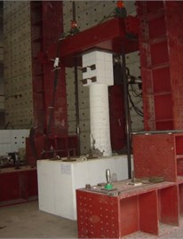
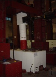
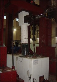
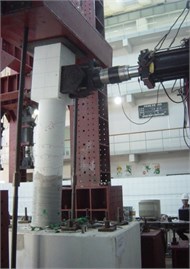
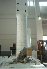
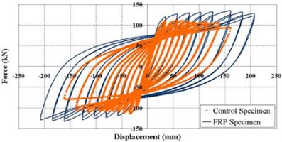
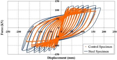
As a test result, an initial crack of the standard specimen occurred horizontally at the interface between a foundation and a pier. And as the load was gradually increased, the horizontal and vertical cracks were occurred at the middle of pier. Finally, as typical flexural failure such as a separation of the concrete cover and crushing was shown, load-carrying capacity was drastically reduced. In case of repaired and retrofitted specimens, the initial cracks occurred horizontally above the boundary of the retrofit plates. As the load was gradually increased, the horizontal and vertical cracks were occurred at the middle of the piers. However, the numbers of vertical cracks were significantly less than those of the standard specimen due to the retrofit effect. As the load was increased, the reinforcement was yielded and showed ductility and then failures were finally shown as a debonding of the retrofit plates. The results of testing, failure and load-displacement curves for each specimen are shown in Figs. 7-9.
Fig. 7Testing photo of the specimens
Retrofit efficiency was evaluated and compared between the standard specimen and repaired and retrofitted specimens by the retrofit method as shown in Fig. 10. The retrofit specimens have relatively higher strength and ductility than the standard specimen. The specimen with FSC plate retrofit has greater retrofit effect than the others relatively. Despite the advantages of retrofit material, the specimens with FRP and steel plate have lower retrofit efficiency because of defects that occur during construction or curing of concrete and bonding performance degradation.
Fig. 8Failure photo of the specimens
a) Standard specimen
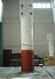
b) Retrofit specimen with steel plate
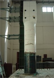
c) Retrofit specimen with FSC plate
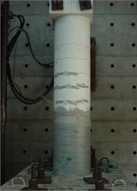
d) Retrofit specimen with CFRP
Fig. 9The load-displacement hysteresis curve
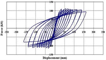
a) Standard specimen
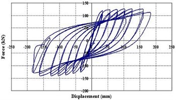
b) Retrofit specimen with steel plate
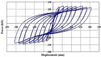
c) Retrofit specimen with FSC plate
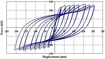
d) Retrofit specimen with CFRP
4. Seismic performance evaluation
The pushover analysis with controlled displacement was implemented for the standard, CFRP, steel plate and FSC plate. With the outcome, the relationship between the top displacement and the base shearing force of the bridge is calculated. The distribution shape of load is generally important in the case of implementing the pushover analysis. Based on the Korean design response spectrum of elasticity [3], the seismic coefficients CA and CV were modified and used. The coefficients were CA= 0.224 and CV= 0.322. Fig. 11 shows the capacity spectrum of each type of specimen. The configuration of capacity spectrum proved that the standard specimen could not satisfy the capacity demand, whereas the seismic retrofit with CFRP and FSC plate specimens achieved all the demanded standards.
Ductility of reinforced concrete beams and piers retrofitted by the jacket retrofit method is generally reduced by brittle failure pattern such as the brittle nature of retrofit material and early debonding at the bonding surface, etc. However, it is insufficient to judge whether the structure has the required ductile capacity with only simple comparison of the displacement-ductility. Thus, this paper evaluated the ductility of each specimen based on the concept of energy. Ductility based on the concept of energy is defined as the ratio of any two of inelastic, elastic, and total energies. In using the energy ratio, however, it is not easy to determine elastic energy and inelastic energy. In this paper, the method of finding a point where the load was changed differently in the load-deflection curve was selected and the inflection point of energy was determined. The method of calculating the energy ductility indices is shown in Fig. 12.
Fig. 10Comparison curves between the standard specimen and retrofit specimens
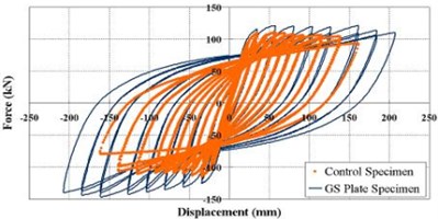
a) Standard-FSC plate retrofit
b) Standard-CFRP retrofit
c) Standard-Steel plate retrofit
Fig. 11Capacity spectrum of the specimens
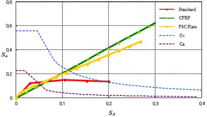
Fig. 12Total, elastic, and inelastic energies
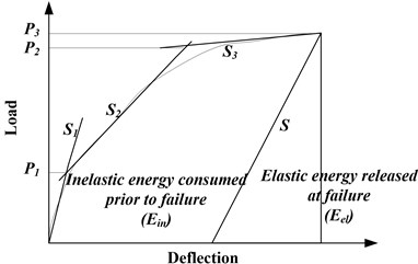
The slopes, S1, S2, and S3 were calculated by numerical integration and the loads, P1 and P2 were the points where another extended slope are met and P3 was ultimate load. The elastic and inelastic energies can be calculated using Eq. (1) and the energy ratio of inelastic energy and total energy can be calculated using Eq. (2):
where S, S1, S2, S3: slopes, P1, P2, P3: loads:
According to the study results by Grace [14], ductile failure is dominant when the energy ratio is greater than 75 %, and semi-ductile is considered when the energy ratio is in range of 70-74 %. If the energy ratio is less than 69 %, brittle failure is dominant.
The ductility of specimens can be classified according to the energy ratio shown in Table 3. The failure type of the retrofit specimens was classified as ductile failure in this test. It is restrictively found that the retrofit structure with the jacket retrofit method secures ductility. It is considered that ductility is increased by the improvement of confinement effect of RC piers because retrofit materials are bonded to the outside of the piers as the type of jackets and material resistance is enough against tensile force under ultimate behaviors.
Table 3Ductility evaluation using the concept of energy
Specimen | Yield load | Ultimate load | Energy ratio (Ei/Et) | Ductility | ||
Load (kN) | Displacement (mm) | Load (kN) | Displacement (mm) | |||
Standard | 65.77 | 13.72 | 110.27 | 51.21 | 0,76 | Ductile |
Steel Plate | 73.23 | 13.85 | 125.17 | 98.72 | 0,87 | Ductile |
CFRP | 74.92 | 13.97 | 120.46 | 105.23 | 0,88 | Ductile |
FSC Plate | 75.06 | 14.09 | 134.38 | 150.17 | 0,92 | Ductile |
5. Conclusions
The seismic repair/retrofit performance of jacket retrofit method for damaged RC piers was evaluated and compared experimentally. This study concluded that all specimens repaired and retrofitted by the jacket retrofit method secured targeted displacement ductility and ultimate load. Maximum load and displacement of the specimen retrofitted by FSC plate are higher than those by CFRP and steel plate and it showed better dissipation capacity of energy. Although there is a disadvantage of less ductile on the specimen retrofitted by the jacket retrofit method, it was found that this disadvantage could be overcome effectively in FSC Plate combined with FRP and steel wire. This was verified numerically by ductility evaluation using the concept of energy. The responses of existing damage bridges are compared with those of retrofitted bridge by jacket method for earthquake of target level, and also seismic performances are evaluated.
As a result, it was experimentally found that if the damaged RC piers were repaired properly and then retrofitted by materials with high ductile capacity, they could secure safety margin and targeted ductility prior to be damaged. However, there were local failures due to defects that occur during construction or curing of concrete and bonding performance degradation. This could cause unexpected failure, and the system and plan should be considered in order to prevent local failures. By the test and analysis results it can be concluded that the proposed seismic retrofit method was found to be valid.
References
-
Zirzba Y. N., Baluch M. H., Basunbul I. A., Sharif A. M., Azad A. K., G. J. Al-Sulaimani Guidelines toward the design of reinforced concrete beams with external plates. ACI Structural Journal, Vol. 91, Issue 6, 1994, p. 639-646.
-
Christopher K. Y. Delamination failure in beams retrofitted with a bonded plate. Journal of Materials in Civil Engineering, Vol. 13, Issue 2, 2001, p. 106-113.
-
Han K. B., Park J. M., Park. S. K. Full-scale pseudodynamic test for bridge retrofitted with seismic isolations. The Baltic Journal of Road and Bridge Engineering, Vol. 3, Issue 1, 2008, p. 38-46.
-
Toutanji Houssam A., Saafi Mohamed Flexural behavior of concrete beams reinforced with glass fiber-reinforced polymer (GFRP) bars. ACI Structural Journal, Vol. 97, Issue 5, 2000, p. 712-719.
-
EI-Mihilmy Mahmoud T., Tedesco Joseph W. Analysis of reinforced concrete beams strengthened with FRP laminates. ASCE, Vol. 126, Issue 6, 2000, p. 684-691.
-
Bonacci J. F., Maalej M. Behavioral trends of RC beams strengthened with externally bonded FRP. Journal of Composites for Construction, 2001, p. 102-113.
-
Christos G. P., Michael F. P., Kent A. H. Fatigue behavior of RC beams strengthened with GFRP sheets. Journal of Composite for Construction, 2001, p. 246-253.
-
Sun Z., Seible F., Priestley M. J. N. Flexural Retrofit of Rectangular Reinforced Concrete Bridge Column by Steel Jacking. Structural Systems Research Project, Report SSRP-93/07, University of California, San Diego, 1993.
-
Priestley M. J. N., Seible F., Xiao Y., Verma R. Steel Jacket restofitting of reinforced concrete bridge columns for enhanced shear strength. Part 1: theoretical considerations and test design. ACI Structural Journal, Vol. 91, Issue 4, 1994, p. 394-405.
-
Matsuda T., Fujiwara H., Higashida N. Effect of carbon fiber reinforcement as a strengthening measure for reinforced concrete bridge piers. Proceedings of 1st US-Japan Workshop on Seismic retrofit of Bridges, Public works Institute, Ministry of Construction, Tsukuba, Japan, 1990.
-
Xiao Y., Wu H., Martin G. R. Prefabricate composite jacking of RC columns for enhanced shear strength. Journal of Structural Engineering, Vol. 125, Issue 3, 1999, p. 225-264.
-
Zile E., Tamuzs V. Inelastic deformation of round concrete columns in triaxial compression. Mechanics of Composite Materials, Vol. 46, Issue 2, 2010, p. 173-182.
-
Zile E., Daugevicius M., Tamuzs V. The effect of pretensioned FRP windings on the behavior of concrete columns in axial compression. Mechanics of Composite Materials, Vol. 45, Issue 5, 2009, p. 457-466.
-
Grace N. F., Soliman A. K., Abdel-Sayed G., Saleh K. R. Behavior and ductility of simple and continuous FRP reinforced beams. Journal of Composites for Construction, Vol. 2, Issue 4, 1998, p. 186-194.
About this article
This study was supported by Research Fund of Chungnam National University in 2015. The authors gratefully acknowledge this support.

