Abstract
Dynamic processes of the armored personnel carrier M113 are investigated in this paper. The model of the system is reduced to seven degrees of freedom (DOF). Six schemes of different integrations were investigated; it was determined that integration schemes with variable time steps allow to reduce calculation time within the applicable range of the calculation error. The weapon’s impact on the dynamic processes of the vehicle is investigated on the uneven terrain. The influence of the standard weaponry on the oscillation peculiarities of the M113 when the vehicle is standing still, moves on the uneven terrain is analyzed. Also, possibilities to use 30 mm cannon on the carrier M113 are examined.
1. Introduction
Military machinery is often operated for a sufficiently long period of time during which it is being modernized, electronic systems, weapons and other items are replaced. At this point, the issues associated with safety and reliability must be addressed. When weapons are changed, dynamic properties of a vehicle change as well. The market offers a large selection of complement items, and the customer can buy the items of different manufacturers, but after they are gathered into a single system, problems during operation may arise. Fedaravičius et al. [1] investigated influence of the shot recoil of various weapons mounted on the armoured vehicle influencing the vehicle oscillation when driving on an uneven terrain. It was found out that usage of a more powerful weapon without suspension modification is not effective. If a more powerful gun system is installed on a carrier, in order to minimize its influence on other systems, recoil dampers can be used. Hongsheng et al. [2] investigated a magnetorheological damper of a gun recoil; the use of such system can solve many problems, but it is a difficult mechatronic system with a PID controller.
It is practically impossible to experimentally investigate all possible combinations of operating parameters of the vehicle due to the testing cost and time requirements. The mathematical modeling of physical systems by applying numerical methods has become a real alternative. However, in order to obtain reliable results, we need to perform model validation and verification. The paper presents a mathematical model for the M113; numerical methods are verified which allow to effectively deal with such problems.
A lot of mathematical models exist which are used for the investigation of the vehicle dynamics. Most commonly used models for vehicles with wheel transmission have 2, 4, 14 and 38 DOF. The simplest one is a quarter-car model [3], which is the 2 DOFs model, where displacements of the sprung mass and a quarter of the vehicle body are taken into consideration. The 4 DOFs model is a half-vehicle model, the vehicle body has 2 DOFs (displacement in vertical direction and rotation), and 1 DOF for each wheel. The 14 DOFs model consists of 6 DOFs of the vehicle (longitudinal, lateral, vertical motions, roll, and yaw) and the 4 DOFs pitch motions of sprung mass, with the remaining 4 DOFs of the rotation of wheels [4]. The 38 DOFs consist of 6 DOFs of the vehicle, and 8 DOFs for each wheel [5]. It is always important to select the best model to the specific case. Męzyk et al. [6] made a mathematical model of a tracked vehicle using Matlab/Simulink software; while making comparison of simulation results and experimental data it was found that simulation results are extremely exact and the mathematical model can be used for the investigation of dynamic parameters of the tracked vehicle. Suspension can be presented by employing the Super-Element model. This model treats the track chain as a single flexible-band and the rest of the running gear as discrete rigid bodies (road wheels, support rollers, drive sprockets, idlers and chassis components) with kinematic constraints. This reduces the size of the problem because the track chain is reduced by a number of rigid bodies with frictional contacts with a single force super-element applied to each road-wheel [7]. Super-element-based model cannot show the dynamic interaction between the track components. Rubinstein and Hitron [8] presented a model, which incorporates detailed description of the track, the suspension system, and the dynamic interaction between its components; the model was first applied to the M113. Literature review showed that impact of weapons reinstallation on the machine dynamic parameters was not widely investigated, and is still a relevant problem.
2. Mathematical model of the armored personnel carrier M113
To investigate the influence of a selected weapon on the dynamical characteristics of the M113 (Fig. 1(a)), a mathematical model was used. The vehicle is modelled as a 2D system, rotation around x axis and displacements in y, z directions (Fig. 1(b)) are only taken into account, the model has 7 DOF.
Using this scheme mathematical model was created. Motion equations are based on the Lagrange equation of the second order:
where: qk is a generalized coordinate; Fk(t,qk,˙qk) is a generalized force.
T is kinetic energy of the system:
where: mk is the mass of the body k; I is the moment of inertia of the vehicle body, ˙qk is the linear velocity of the body k, q7 is the angular velocity of the vehicle body.
Π is the potential energy of the system:
+12k5(q5-z5)2+12k6(q6-q7(l3+l4+l11)-q1)2
+12k7(q6-q7(l4+l11)-q2)2+12k8(q6-q7(l11)-q3)2
+12k9(q6+q7(l5-l11)-q4)2+12k10(q6+q7(l5+l6-l11)-q5)2.
Φ is the dissipative function:
Using Eqs. (3), (4) and (1), equations of motion may be written:
-c6(˙q6-˙q7(l3+l4+l11)-˙q1)=-m1g,
-c10(˙q6+˙q7(l5+l6-l11)-˙q5)=-m5g,
+k8(q6-q7(l11)-q3)+k9(q6+q7(l5-l11)-q4)
+k10(q6+q7(l5+l6-l11)-q5)+c6(˙q6-˙q7(l3+l4+l11)-˙q1)
+c10(˙q6+˙q7(l5+l6-l11)-˙q5)=-m6g,
-k7(l4+l11)(q6-q7(l4+l11)-q2)-k8(l11)(q6-q7(l11)-q3)
+k9(l5-l11)(q6+q7(l5-l11)-q4)+k10(l5+l6-l11)(q6+q7(l5+l6-l11)-q5)
-c6(l3+l4+l11)(˙q6-˙q7(l3+l4+l11)-˙q1)
+c10(l5+l6-l11)(˙q6+˙q7(l5+l6-l11)-˙q5)=-F(l10-l9).
¨qi, i=1,…, 7 – are linear and angular accelerations.
Fig. 1a) The M113 b) Dynamic model of the M113
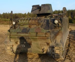
a)
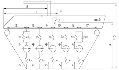
b)
In order to solve the mathematical model, different numerical integration schemes may be used, and the chosen method will have the influence on the accuracy of the results and the calculation time. Three types of mathematical errors that appear in this process may be defined [9]: truncation error; round-off error; global error. It is very important to choose the appropriate integration step, thereby reducing the calculation error and computation time. Thompson and Grest [11] proposed to use the integration step ∆; Zhang and Campbell [12] found that it is not always appropriate, and the integration step was proposed.
In this paper 6 different integration schemes are investigated. Three integration schemes with the constant time step: Euler; Modified Euler; Runge-Kutta of 4th order. Three integration schemes with variable time steps: ODE23, which uses Runge-Kutta integration scheme of 2nd and 3rd order; ODE45, uses Runge-Kutta of 4th and 5th order, and ODE15S.
3. Findings of the modelling
In this part of the paper verification and validation of the system is made and the simulation results are presented.
3.1. System verification
In order to compare the different numerical methods, the Eq. (6) was solved analytically; we assume that , then Eq. (6) can be written:
Such equation has an analytical solution; when the initial displacement and velocity equal to zero , and Eq. (12) can be simplified:
where: .
For the purpose of result verification, the integration time step 10-4 s and simulation time 1 s were selected; initial data is presented in Table 1. We can see from Fig. 2 that the selected time step is too small when using Euler Method.
Fig. 2Verification of integration schemes
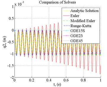
Fig. 3Errors using different integration schemes
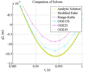
Table 1Initial data
Parameter | Value | Parameter | Value |
Stiffness , 1,…, 5 | 2,15∙107 N/m | Unsprung mass of 1 and 5 axes | 160 kg |
Unsprung mass of 2, 3, 4 axes | 120 kg | Sprung mass not loaded | 10120 kg |
Sprung mass loaded | 11360 kg | Inertia not loaded | 21900 kg∙m2 |
Inertia loaded | 24600 kg∙m2 | Suspension stiffness , 6,…, 10 | 6,5∙104 N/m |
Suspension damping | 1800 Ns/m | l1 | 2.34 (m61); 2.45 (m62) |
0.68 m | l3 | 0.66 m | |
0.66 m | l5 | 0.66 m | |
0.66 m | l7 | 0.68 m | |
1.800 m | l9 | 1.3 m | |
1.3 m | l10 | 2.3 m | |
The geometrical parameters of the vehicle have been set with the loaded and unloaded vehicle. The loaded vehicle is with a full crew and the equipment. Stiffness coefficients were determined from the experimental measurements. | |||
The error increases monotonically, this method cannot be used for such type of tasks with the selected integration time step. The results obtained when using other integration schemes corresponds to the analytical solution.
In Fig. 3 we can see errors when using proposed integration schemes (without Euler), the best result was obtained when using Modified Euler, Runge-Kutta (4 order) and ODE45 methods.
When using the ODE15S, error has increased, and the biggest error was found when ODE23 method was used (Fig. 3). In order to solve this task using ODE23, 525 iterations were made, using ODE45 637 iterations, and using ODE15S 449 iterations were made to achieve the solution.
3.2. System validation
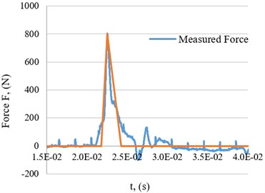
Recoil force of the 12.7 mm gun was measured (Fig. 4); measured recoil curve is presented in Fig. 5; approximated force for simulation was used.
Fig. 4Recoil force measurement equipment
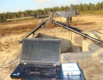
Fig. 5Numerical value of the recoil force
For the purpose of the system validation, the case was chosen when the vehicle stands still and makes one shot, simulation time equals to 10 s. Three methods were used for the solution of the case: Modified Euler, Runge-Kutta, ODE 45. During the investigation it was identified that the largest errors are received when 1.648 s and 2.356 s.
When using the ODE45 integration scheme, with the integration time step 1∙10-5 and , the error is less than 0.05 % at the time moment 1.648 s and 2.356 s, the calculation time is 54.8 s. When using Modified Euler method with error limits of 0.05 %, the selected time step should be 3∙10-5 s, the calculation time 267.4 s. When using Runge-Kutta method with error limit of 0.05 %, the selected time step should be 1∙10-5 s, calculation time 129 s. When comparing three different integration schemes, the shortest computational time was obtained using ODE45 method. Modified Euler is 4.88 times slower, and Runge-Kutta 2.35 times, respectively. Therefore, ODE45 method was employed in further investigations.
In Fig. 6 three cases are presented, one shot, two shots, and three shots are fired.
The 12.7 mm gun is often used on the M113 and the recoil has no significant effect on the vehicle dynamics, this is proved by the data given in Fig. 6. In case one shot, the maximum displacement of the vehicle body is about 5 mm. When three shots are fired, the displacement is about 9 mm, in this case, not only the amplitude, but the oscillation frequency changes as well. An interesting effect is obtained when shots are fired at a certain frequency. In one particular case, single shots are fired with the interval of 1.85 s, then after each shot the amplitude increases and this has a negative impact on the dynamic characteristics of the vehicle, the crew inside in particular.
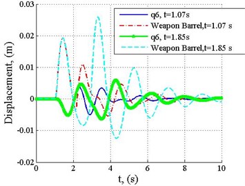
Fig. 7 shows displacement of a weapon barrel, when two shots are fired. After the first shot, the barrel end rises by 19 mm, and after the second, when the interval is 1.85 seconds, the displacement of the barrel is 25 mm. However, time interval is reduced to 1.07 s, the amplitude after the second shot will reduce to 11 mm. In real word scenario it is very difficult for the person shooting to determine the correct time intervals; which are points in time when the machine returns to its initial position.
It would seem that it is necessary to fire when the time is 1.07 s, as it allows to reduce the amplitude, however, after a closer examination of the case it can be observed that both in the first and the second instances, at the moment of firing, the end of the barrel is roughly in the same place, which means that it does not have a significant influence on the accuracy. However, people experience better comfort when firing takes place every 1.07 s (half of the period of the oscillation).
Fig. 6Displacement of the vehicle body, when the vehicle velocity v= 0
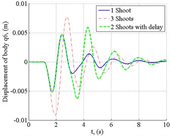
Fig. 7Displacement of a weapon barrel, when the vehicle velocity v= 0, shooting intervals are 1.07 and 1.85 s
4. Investigation of dynamic parameters of the armoured carrier M-113 with 30 mm weapon
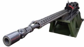
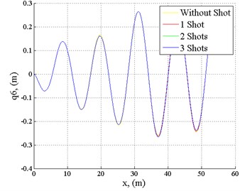
For investigation of dynamic parameters of the armoured personnel carrier M113 on the uneven terrain, road surface roughness was estimated (Fig. 9, such roughness of the plough may occur in winter, when the soil is frozen); 30 mm weapon (muzzle velocity – 1385 m/s, mass of the shell – 0.725 kg; Fig. 8) was installed. By using a simple mathematical model, and making an assumption, that the recoil force curve will have the same shape as the 12.7 mm gun, and the operating time will only vary, it was found out that the maximum recoil force will be 11150 N.
Fig. 8Rheinmetall’s 30 mm machinegun
Three different cases were investigated, velocities of 10, 20 and 40 km/h, as well as three shooting modes when the vehicle moves without firing, the vehicle fires one, two, and three times. Intervals between shots are chosen so that the worst condition would be created and oscillations would be caused this way.
When the vehicle velocity is 10 km/h, suspension absorbs roughness (Fig. 10), shooting with the 30 mm machinegun increases oscillations, but such increase does not have a significant impact on the vehicle dynamics. The interval between shots was selected of 1.85 s (such interval had the worst impact on vehicle dynamics).
When the vehicle velocity is 20 km/h (Fig. 11), displacement of the carrier body is a little smaller than the roughness of the road surface, but the situation is worse compared to the first case, when the velocity was 10 km/h, and shots even decreased oscillations. When vehicle velocity is 40 km/h, we can see (Fig. 12) a significant increase of the vehicle body displacements; shooting does not have any significant effect on the vehicle dynamics. The 30 mm weapon may be mounted on the armoured vehicle without an additional adjustment of the suspension. This will have no significant impact on the dynamics of the machine and the comfort for people, but by choosing time intervals between the shots it is possible to reduce as well as increase the oscillation frequency of the vehicle body.
The best time to fire is at the moment when the machine returns to the initial position after the shot.
Fig. 9Road surface
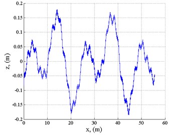
Fig. 10Displacement of the vehicle body, when vehicle velocity v= 10 km/h
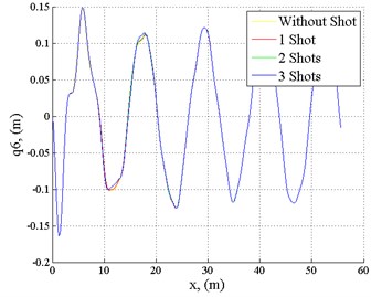
Fig. 11Displacement of the carrier body, when the vehicle velocity v= 20 km/h
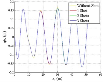
Fig. 12Displacement of the carrier body, when the vehicle velocity v= 40 km/h
5. Conclusions
During the investigation it was identified that while firing in series, the oscillation amplitude of the vehicle as well as the frequency changes; when firing single shots, it is possible to either reduce or increase the oscillation frequency of the vehicle body. This will affect the crew’s comfort, but not the shooting accuracy.
During the investigation on rough surface, it was found out that the 30 mm weapon does not have any significant impact on the carrier dynamics. For the proposed surface, it was found out that maximum permissible velocity is up to 20 km/h. Canons of up to 30 mm caliber may be mounted on the armoured personnel carrier M113 without making any additional changes to the vehicle’s suspension.
References
-
Fedaravičius A., Jonevičius V., Survila A., Pincevičius A. Dynamics study of the carrier HMMWV M1151. Journal of Vibroengineering, Vol. 15, Issue 3, 2013, p. 1619-1626.
-
Hongsheng H., Jiong W., Suxiang Q., Yancheng L., Xuezheng J. Investigation on controllability of a Magnetorheological gun recoil damper. Proceedings of the 2009 IEEE International Conference on Information and Automation, 2009, p. 1044-1049.
-
Ngwangwa H. M., Heyns P. S. Application of an ANN-based methodology for road surface condition identification on mining vehicles and roads. Journal of Terramechanics, Vol. 53, 2014, p. 59-74.
-
Shyrokau B., Wang D., Savitski D., Ivanov V. Vehicle dynamics control with energy recuperation based on control allocation for independent wheel motors and brake system. International Journal of Powertrains, Vol. 2, Issues 2-3, 2013, p. 153-181.
-
Venture G., Ripert P. J., Khalil W., Gautier M., Bodson P. Modeling and identification of passenger car dynamics using robotics formalism. IEEE Transactions on Intelligent Transportation Systems, Vol. 7, 2006, p. 349-359.
-
Męzyk A., Switonski E., Kciuk S., Klein W. Modelling and investigation of dynamic parameters of tracked vehicles. Mechanics and Mechanical Engineering, Vol. 15, Issue 4, 2011, p. 115-130.
-
Madsen J., Heyn T., Negrut D. Methods for Tracked Vehicle System Modelling and Simulation. Technical Report, http://sbel.wisc.edu/documents/TR-2010-01.pdf, 2010, p. 53.
-
Rubinstein D., Hitron R. A. detailed multi-body model for dynamic simulation of off-road tracked vehicles. Journal of Terramechanics, Vol. 41, 2004, p. 163-173.
-
Fraige F. Y., Langston P. A. Integration schemes and damping algorithms in distinct element models. Advanced Powder Technology, Vol. 15, Issue 2, 2004, p. 227-245.
-
Haile J. M. Molecular Dynamics Simulation: Elementary Methods. 1992, p. 512.
-
Thompson P., Grest G. Granular flow: friction and the dilatancy transition. Physical Review Letters, Vol. 67, Issue 13, 1991, p. 1751-1754.
-
Zhang Y., Campbell C. The interface between liquid-like and solid-like behaviour in two-dimensional granular flows. Journal of Fluid Mechanics, Vol. 237, 1992, p. 541-568.
-
Kruggel-Emden H., Sturm M., Wirtz S., Scherer V. Selection of an appropriate time integration scheme for the discrete element method (DEM). Computers and Chemical Engineering, Vol. 32, 2008, p. 2263-2279.

