Abstract
Since earlier days, most of the failures encountered by the structures or machines are mainly due to material fatigue. The dynamic behaviour of the beam may change when cracks begin to appear in it. Knowledge of these changes in the dynamic individualism is important in crack detection as well as in structure or in machine design. This paper deals with systematic study on the free vibration of Euler-Bernoulli beam containing open edge transverse cracks. In this study, two springs steel materials (EN 8 and EN 47) are considered. The effect of the top side cracks and bottom side cracks on the natural frequency of a cantilever beam is discussed. The natural frequency of a cracked case cantilever beam is investigated numerically using FE analysis software ANSYS. Experimental work is done by using DeweFRF to investigate the natural frequency of cracked beams for strong validation of the numerical results. The results of this study suggest that the average value of natural frequencies for all top side cracked beams are identical to the average value of natural frequency for all bottom side cracked beams. This is true for both EN 47 and EN 8. Hence, it is clear that the dynamic characteristic (natural frequency) is not changing, when same configuration of cracks is either on top or bottom side of the beam. The natural frequencies for EN 8 material are comparatively on higher side than EN 47 material for the same crack configurations. In most of the cracked cases, the damping effect of EN 47 is greater than EN 8. It is also found that as crack location increases at constant crack depth, then natural frequency increases. At the last location, as crack depth increases, natural frequencies almost remain same. It is observed that, the presence of top side crack and bottom side crack of the same configuration in the cantilever beam is not a function of natural frequency, when cantilever beam is of a square cross section.
1. Introduction
Since more than last two decades, the problem of crack and its detection in structures or beams has attained significant role. An inadequate numerical and analytical study exists on vibration of beam with cracks. Shifrin and Rutolo [1] proposed a new method for enumerating natural frequencies of a beam with an arbitrary number of transverse open cracks. Cracks are characterized as massless rotational springs. Compared to the substitute methods which make use of continuous model of beam, the calculation time required here was reduced due to the reduced dimension of the matrix. The experimental investigations of the effects of cracks on the first two modes of vibrating beams for both hinged-hinged and fixed-free boundary conditions is elaborated by Owolabi and Swamidas [2]. The Frequency Response Function (FRF) amplitudes and changes in natural frequencies obtained from the measurements of dynamic responses of cracked beams as a function of crack depth and location of crack are used for the detection of crack. Zheng and Kessissoglou [3] obtained the natural frequencies and mode shapes of cracked beam using Finite Element Method (FEM). The total flexibility matrix is established by adding overall additional flexibility matrix to the flexibility matrix of the corresponding intact beam element. The results when compared with analytical results show more accuracy than when the local additional flexibility matrix was used in the place of overall additional stiffness matrix. Chen et al. [4] carry out experimental investigation to determine the location and size of crack. The intersection of curves of stiffness versus crack location for the first three natural frequencies obtained from the vibration of the cracked cantilever beam predicts the crack location and crack depth. Patil and Maiti [5] verified a method to predict the location and depth of crack experimentally for cantilever beams with edge crack. The energy approach method is used for analysis and the crack is represented as a rotational spring. For a particular mode, varying crack location, a plot of stiffness versus crack location is obtained. The intersection of these curves consequent to the three modes gives the crack location and the associated rotational spring stiffness. Sadettin [6] conducted the number of experiments on edge cracked cantilever beam to see the effect of crack on different vibration parameters.
Kirishmer [11], Thomson [12] and Petroski [13, 14] illustrated the effects of cracks on structural response through simple reduced section models of cracked beams using energy methods, and discussed the effect of the size and location of the crack to the natural frequency and vibration mode of the damaged beam. Inagaki et al. [15], estimated the crack size and position by natural vibration analysis of cracked rotors. Dealing with the same subject and using modal analysis, Grabowski [16] also came to the conclusion that there is a strong dependence of vibrational behaviour of cracked rotors on the crack position and magnitude. Mays and Davies [17] proposed a method for the prediction of the crack location and magnitude of a rotating cracked rotor, from frequency measurements and analytically obtained mode shapes. Mohammad et al. [18] are studied the small scale effect on the axial vibration of a tapered nanorod employing nonlocal elasticity theory. To analyze the mechanical behaviour of nanoscale materials, they used non-local elasticity theory. Differential quadrature method (DQM) is applied for different end conditions. The small scale effects on the natural frequencies of the tapered rods are investigated. They observed that the non-local vibration solutions are always smaller than their local counterparts for both uniform and tapered nanorod. Yayli [19] proposed a finite element procedure for computations of natural frequencies based on strain gradient elasticity theory. The results reveal that for the microbeam with varying cross section comparable to its material length scale parameter, the effect of strain gradient is significant. They observed that the frequencies of microbeam can be controlled by choosing proper values of depths. Yayli [20] is studied the free axial vibration response of carbon nanotubes (CNTs) with arbitrary boundary conditions based on non- local elasticity theory. A unified analytical method has been developed, which can be used for a nanorod with any types of boundary conditions. It is suggested that by controlling the spring parameters and natural frequencies, the structures of nanotubes can be produced for nanosized devices. Lam et al. [21] observed experimentally that the normalized bending stiffness increases by about 2.4 times when the thickness was reduced from 115 to 20 µm. Stolken and Evans [22] examined that the plastic work hardening shows a great increase as the microbeam thickness decreases from 50 to 12.5 µm. Demir et al. [24] have examined nonclassical frequencies of carbon nanotubes based on shear deformable beam theory by discrete singular convolution technique. Akgoz and Civalek [25] have analyzed microsized beams for various boundary conditions based on strain gradient elasticity theory. In adition, small scale effect of the torsion response of bars and buckling of axially loaded microscaled a beam has been presented by Kahrobaiyan et al. [26] and Akgoz and Civalek [27], respectively.
From the detailed literature survey, it has been observed that most of the researchers have worked on the cracked cantilever beam. They have investigated the effect of crack locations and crack depths on different vibrating properties like natural frequency, damping factor and resonance amplitude. None of the researchers has worked on the top side and bottom side crack on the cantilever beam of square cross section. Also, the comparative vibration studies on EN 8 and EN 47 structural material are missing in the literature. It is very essential to understand the dynamics of the cracked cantilever beam for the specific configurations because the natural frequency is used as basic criteria for predicting the location and the size of the damage.
The present work deals with both numerical and experimental investigations on free vibration of cracked cantilever beam of two practically important spring steel beams EN 8 and EN 47 materials; having square cross section. Effect of top side cracks and bottom side cracks on vibration parameters are investigated by finite element method and experimental method.
2. Theory
The beam with a transverse edge crack is clamped at left end, free at other end, it has a uniform square cross-section. The Euler-Bernoulli beam model is assumed as length to width ratio of a beam is 18. The crack is assumed to be an open crack in this study.
2.1. Governing equation of free vibration of a intact cantilever beam
Consider an elastic beam of length l subjected to a transverse force f(x,t) per unit length and w(x,t) is the transverse displacement of the string shown in Fig. 1(a). The free body diagram of an element of a beam shown in Fig. 1(b), where M(x,t) is the bending moment, V(x,t) is the shear force.
Since the inertia force acting on the element of the beam is:
The force equation of motion in the z direction gives:
where ρ is the mass density and A(x) is the cross-sectional area of the beam. The moment equation of motion about the y axis passing through a point O in Fig. 1(b) leads to:
Fig. 1An elastic beam
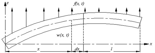
a) A beam in bending [8]
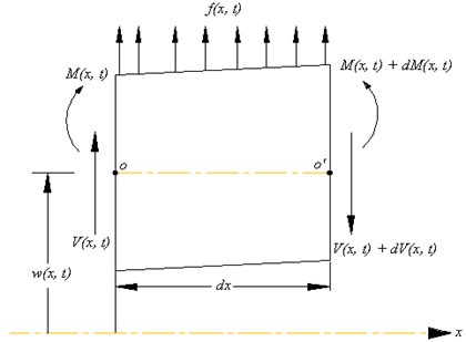
b) Free body diagram of a beam in bending [8]
By writing dV=∂V∂x∂x and dM=∂M∂x∂x and disregarding terms involving second powers in dx Eqs. (1) and (2) can be written as:
By using the relation V=∂M∂x from Eq. (4), Eq. (3) becomes:
From Euler-Bernoulli theory of bending, the relationship between bending moment and deflection can be expressed as:
where E is the Young’s modulus and I(x) is the moment of inertia of the beam cross section about y axis. Inserting Eq. (6) into Eq. (5), we obtain the equation of motion for the forced lateral vibration of a nonuniform beam:
For a uniform beam, Eq. (7) reduces to:
For free vibration, f(x,t)=0, and so the equation of motion becomes:
Since the equation of motion involves a second-order derivative with respect to time and a fourth-order derivative with respect to x, two initial conditions and four boundary conditions are needed for finding a unique solution for w(x,t). Usually, the values of lateral displacement and velocity are specified as w0(x) and w'0(x) at t= 0, so that the initial conditions become:
The free vibration solution can be found using the method of separation of variables as:
Substituting Eq. (12) into Eq. (9) and rearranging leads to:
where a=w2 is a positive constant. Eq. (13) can be written as two equations:
The solution of Eq. (15) can be expressed as:
where A and B are constants that can be found from the initial conditions. For the solution of Eq. (14), we assume:
where C and s are constants, and derive the auxiliary equation as:
The roots of this equation are:
Hence the solution of Eq. (14) becomes:
where C1, C2, C3, C4 are constants. Eq. (21) can be expressed as:
The cantilever boundary conditions are:
Substituting cantilever boundary condition in Eq. (22), we obtain:
β[C2+C4]=0,C2=-C4,
C1(coshβl+cosβl)+C2(sinhβl+sinβl)=0,
C1(sinhβl-sinβl)+C2(coshβl+cosβl)=0.
From Eq. (29) and (30), we obtain:
which reduces to:
This last equation is satisfied by a number of values of βl, corresponding to each normal mode of oscillation, which for the first and second modes are 1.875 and 4.695, respectively. The natural frequency of intact cantilever beam for the first mode is hence given by:
2.2. Formulation of a cracked cantilever beam
The presence of crack increases the local flexibility in the beam, and hence there is a jump in the slope of a slender beam in the vicinity of the crack section. The magnitude of the stiffness is selected so that the rotation of the spring due to the moment at the crack section is equal to the jump in slope due to additional flexibility. As the bending vibration is studied, edge crack is modelled as a rotational spring with a lumped stiffness. The crack is assumed open. Based on this modelling, the beam is divided into two segments: the first and second segments are left and right-hand side of the crack, respectively. When this equation is solved by applying beam boundary conditions and compatibility relations, the natural frequency of the cracked beam is finally obtained:
where Ai and Bi, i= 1, 2, 3, 4, are constants to be determined from the boundary conditions, λ4=ω2ρAL4/EI, ω is the vibration angular Velocity.
2.3. Application to a cracked cantilever beam
The boundary conditions for the structural member under consideration (see Fig. 2), are:
Fig. 2Cracked cantilever beam model [23]
![Cracked cantilever beam model [23]](https://static-01.extrica.com/articles/17394/17394-img3.jpg)
If R=L1/L is the dimensionless crack position, the continuity conditions at the crack position are:
and the compatibility condition due to rotational flexibility is:
Eqs. (33) and (34) with equations (35)-(38) yield the characteristics equation [23] which, in turn, yields the natural frequencies of a cracked cantilever beam.
3. Experimental study
The aim of experimentation is to monitor the change in natural frequency and damping in a cantilever beam due to presence of transverse edge crack.
3.1. Experimental setup
The instruments used for experimental analysis are accelerometer, DeweFRF and related accessories, as shown in Fig. 3. Specimens of EN 8 and EN 47 material are used to study the effects of cracks on vibration parameters. Both the materials are tested in ELCA Lab, Pune, India, for material properties like young’s modulus and density. The material properties and specimen geometric properties are shown in Table 1. Poisson’s ratio (μ) is assumed as 0.3. Wire EDM process is used to produce cracks on the specimens.
The beam is clamped at one end by a fixture and another end is free. An accelerometer of piezo electric type is mounted on the beam is used to measure the acceleration of the vibrating body. A vibration of transverse waves is comparatively on upper side than longitudinal waves [7]. Again, pure bending mode is obtained at the first natural frequency only in the crosswise direction. Owing to this reason, only the vibration in the transverse direction is considered in this study.
Fig. 3Experimental set-up
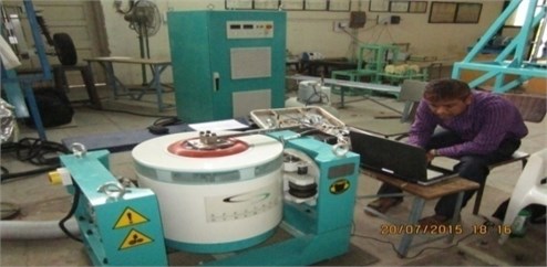
Table 1Material properties and geometric properties of specimen
Property | EN 8 | EN 47 |
Density (kg/m3) | 7820 | 7800 |
Modulus of Elasticity (N/m2) | 2.104×10¹¹ | 1.95×10¹¹ |
Length of specimen (m) | 0.360 | 0.360 |
Cross section of specimen (m2) | 0.02×0.02 | 0.02×0.02 |
3.2. Crack configurations
Total 48 cracked specimens are used in this study, to find out how the cracks affect the dynamic behavior of a cantilever beam.
Fig. 4Schematic diagram of a cracked cantilever beam

a) Cantilever beam with top side transverse crack

b) Cantilever beam with bottom side transverse crack
Case 1: In this case, 12 specimens of EN 8 material are considered and cracks are taken on the specimen from top side. Single transverse crack is taken on each specimen. Case 1 is subdivided into 3 sub cases. In the first sub case, 120 mm crack location is selected from the cantilever end and at this location crack depth is varied by an interval of 4 mm from 4 mm to 16 mm. The second and third sub cases are similar to first sub case, only difference is that instead of 120 mm crack location, 180 mm and 240 mm crack location is chosen for the second and third sub case respectively.
Case 2: This case is similar to case 1, the only difference is that cracks are taken on the beam from the bottom side.
Case 3: This case is similar to case 1, but instead of EN 8 material, EN 47 material is chosen.
Case 4: This case is similar to case 2, but instead of EN 8 material, EN 47 material is chosen.
4. Finite element modelling and analysis
ANSYS [10] finite element program is used to determine natural frequencies of the undamaged as well as cracked beams. For this purpose, rectangle area is created. This area is extruded in the third direction to get the 3 D model. Then at the required location, small rectangular area of crack of 0.5 mm width and required depth is created and extruded. Then small volume of crack is subtracted from large volume of cantilever beam to obtain cracked three dimensional models.
The width of crack is kept constant throughout its depth in this study. A 20 node structural solid element (solid 186) is selected for modelling the beam because of some special features like stress stiffening, large strain, and large deflection. Finite element boundary conditions are applied on the beam to constrain all degrees of freedom of the extreme left hand end of the beam. The Block Lanczos eigenvalue solver is used to calculate the natural frequencies of the beams.
Fig. 5Cracked beam finite element modelling

Fig. 6Natural frequency plot, EN 47 TS crack, crack details: L1/L= 0.33; a/H= 0.8

Fig. 7Natural frequency plot, EN 8 BS crack, crack details: L1/L= 0.33; a/H= 0.8

5. Results
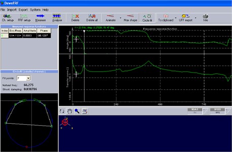
Experimental values of natural frequency and damping factor determined by DeweFRF are shown in Figs. 8-9. In Figs. 10-11, through finite element analysis it is found that, the average value of natural frequency of top side cracked beams is identical to the average value of natural frequency of bottom side cracked beams of EN 8 material. The same theory holds true for EN 47 material also.
Fig. 8Natural frequency and damping factor Plot by DeweFRF, EN 47 TS crack, crack details: L1/L= 0.33; a/H= 0.8
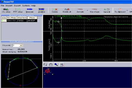
Fig. 9Natural frequency and damping factor plot by DeweFRF, EN 8 BS crack, crack details: L1/L= 0.33; a/H= 0.8
Experimental results showed some error between the average value of natural frequency of top side and bottom side cracked beams. Small experimental deviation in results is mainly due to presence of some error in the boundary conditions. The existing fixture is not perfectly rigid, means it is associated with some flexibility property. This flexibility property changes the vibrating natural frequency of the beam. During experimentation time, a free length (unclamped length) of the beam may get changed by 1 or 2 mm from the required length, therefore, it leads to change the value of natural frequency of the beam significantly. It is get clear from Eq. (32). Also, the presence of manufacturing defects, machining induced residual stresses in the beam changes its natural frequency. The presence of top side crack or bottom side crack in the beam for the same crack configuration gives the same value of flexural rigidity, due to square cross section of a cantilever beam. So, natural frequency of a cantilever beam of square cross section is independent of top side or bottom side cracks.
It is also found that when the crack location increases from the fixed end and keeping the crack depth constant, then the value of natural frequency remains unvarying. This holds true when crack depth is either equal to or less than 20 % of the beam depth. A constant value of natural frequency means an almost constant stiffness of the beam. For larger crack depth, natural frequency increases notably with crack location.
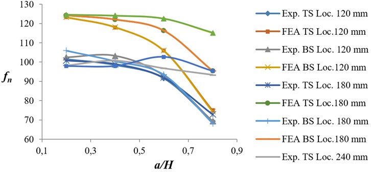
From Figs. 12-13, it is found that as crack depth was increased for any unique location, then natural frequency of the beam decreases, attributed mainly to the reduction in rigidity of the beam. Therefore, it is clear that change in crack depth is a function of natural frequency. The natural frequency of the beam decreases considerably when crack depth increases to 80 % of the beam depth, and it is least affected when crack depth is either 20 % or less than 20 % of the depth the beam. It is also found that for 120 mm crack location, when crack depth was increased, then natural frequency decreases more abruptly than 180 mm and 240 mm crack location. This is because of more damping effect at 120 mm crack location.
Fig. 10Variation of natural frequency ratio versus crack location ratio for EN 47 specimens
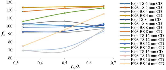
Fig. 11Variation of natural frequency ratio versus crack location ratio for EN 8 specimens
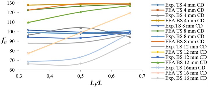
Fig. 12Variation of natural frequency ratio versus crack depth ratio for EN 47 specimens
From Fig. 14, it is found that values of natural frequency for EN 8 cracked beams is comparatively on higher side than EN 47 cracked beams, because of higher stiffness properties of EN 8 material. From Fig. 15, it is observed that as crack depth is increased at any unique location, then damping factor in the beam increases. This is mainly due to decrease in stiffness of the beam. A greater increase in damping factor is observed as crack depth increases for 120 mm crack location from the fixed end, than for 180 mm and 240 mm crack locations. This is due to the fact that the cracks which are nearer to the fixed end contribute a larger damping effect in the beam. It is also found that the damping factor of EN 47 material is greater than EN 8.
Fig. 13Variation of natural frequency ratio versus crack depth ratio for EN 8 specimens
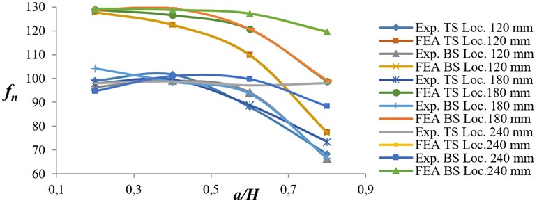
Fig. 14Variation of natural frequency ratio versus crack location ratio for EN 8 and EN 47 specimens
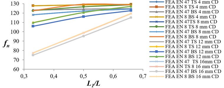
Fig. 15Variation of damping factor versus crack depth ratio for EN 8 and EN 47 specimens

6. Conclusions
By finite element analysis, the natural frequencies present in the cracked cantilever beams are found to confirm the experimental results.
The following conclusion can be drawn from this study.
1) Natural frequency of a cantilever beam of square cross section is independent of top side or bottom side crack of same configuration.
2) The average value of natural frequency for top side cracked beams is identical to the average value of natural frequency for bottom side cracked beams for the same cracked configuration.
3) When the location of crack is kept constant and crack depth is increased, then natural frequency of the beam decreases.
4) When the crack depth is kept constant and crack location is varied from the fixed end, then natural frequency of the beam increases.
5) When the crack depth is increased at any unique location then damping factor in the beam increases.
6) Natural frequency for EN 8 cracked beams is relatively on higher side than EN 47 cracked beams. From this it can be concluded that EN 8 material will take care of dynamic loads effectively than EN 47 material, when put in the service.
References
-
Shifrin E. I., Rutolo R. Natural frequencies of a beam with an arbitrary number of cracks. Journal of Sound and Vibration, Vol. 222, Issue 3, 1999, p. 409-423.
-
Owolabi G. M., Swamidas A. S. J., Seshadri R. Crack detection in beams using changes in frequencies and amplitudes of frequency response functions. Journal of Sound and Vibration, Vol. 265, 2003, p. 1-22.
-
Zheng D. Y., Kessissoglou N. J. K. Free vibrational analysis of cracked beam by finite element method. Journal of Sound and Vibration, Vol. 273, 2004, p. 457-475.
-
Chen X. F., Li B., Ma J. X., He Z. J. Detection of crack location and size in structures using wavelet finite element methods. Journal of Sound and Vibration, Vol. 285, 2005, p. 767-782.
-
Patil D. P., Maiti S. K. Experimental verification of a method of detection of multiple cracks in beams based on frequency measurements. Journal of Sound and Vibration, Vol. 281, 2005, p. 439-451.
-
Sadettin Orhan Analysis of free and forced vibration of a cracked cantilever beam. Non Destructive Testing and Evaluation International, Vol. 40, Issue 6, 2007, p. 443-450.
-
Sansalone M., Nicholas J. C., Nelson N. H. A finite element study of transient wave propagation in plates. Journal of Research of the National Bureau of Standards, Vol. 92, Issue 4, 1987, p. 267-278.
-
Rao S. S. Mechanical Vibrations. Vol. 4, Dorling Kindersley, Pvt. Ltd., Pearson Education, India.
-
ANSYS Release 12.1, ANSYS Inc.
-
ANSYS Element Manuals, ANSYS Inc.
-
Kirishmer P. G. The effect of discontinuities on the natural frequency of beams. Proceedings of the American Society of Testing and Materials, Vol. 44, 1944, p. 897-904.
-
Thomson W. J. Vibration of slender bars with discontinuities in stiffness. Journal of Applied Mechanics, Vol. 17, 1943, p. 203-207.
-
Petroski H. J. Simple static and dynamic models for the cracked elastic beam. International Journal of Fracture, Vol. 17, 1981, p. 71-76.
-
Petroski H. J. Structural dynamics of piping with stable cracks. International Journal of Pressure Vessels and Piping, Vol. 13, 1983, p. 1-18.
-
Inagaki T., Kanki H., Shiraki K. Transverse vibration of a general cracked- rotor bearing system. Journal of Mechanical Design, Vol. 104, 1981, p. 1-11.
-
Grabowski B. The vibrational behavior of a turbine rotor containing the transverse crack. Journal of Mechanical Design, Vol. 102, 1979, p. 140-146.
-
Mayes I. W., Davies W. G. R. The vibrational behavior of a rotating shaft system containing a transverse crack. Institution of Mechanical Engineers Conference Publication, Vibrations in Rotating Machinery, 1976, p. 168-176.
-
Mohammad D., Ali F., Moslem M. Axial vibration of a tapered nanorod based on non-local elasticity theory and differential quadrature method. Mechanics Research Communications, Vol. 39, 2012, p. 23-27.
-
Yayli M. O. Free vibration behavior of a gradient elastic beam with varying cross section. Shock and Vibration, Vol. 2014, 2014, p. 801696.
-
Yayli M. O. On the axial vibration of carbon nanotubes with different boundary conditions. Micro and Nano Letters, Vol. 9, Issue 11, 2014, p. 807-811.
-
Lam D. C. C., Yang F., Chong A. C. M., Wang J., Tong P. Experiments and theory in strain gradient elasticity. Journal of the Mechanics and Physics of Solids, Vol. 51, Issue 8, 2003, p. 1477-1508.
-
Stolken J. S., Evans A. G. Microbend test method for measuring the plasticity length scale. Acta Materialai, Vol. 46, Issue 14, 1998, p. 5109-5115.
-
Rizos P. F., Aspragathos N. Identification of crack location and magnitude in a cantilever beam from the vibration modes. Journal of Sound and Vibration, Vol. 138, Issue 3, 1990, p. 381-388.
-
Demir C., Civalek O., Akgoz B. Free vibration analysis of carbon nanotubes based on shear deformable beam theory by discrete singular convolution technique. Mathematical and Computational Applications, Vol. 15, Issue 1, 2010, p. 57-65.
-
Akgoz B., Civalek O. Analysis of micro-sized beams for various boundary conditions based on the strain gradient elasticity theory. Archive of Applied Mechanics, Vol. 82, Issue 3, 2012, p. 423-443.
-
Kahrobaiyan M. H., Tajalli S. A., Movahhedy M. R., Akbari J., Ahmadian M. T. Torsion of strain gradient bars. International Journal of Engineering Science, Vol. 49, Issue 9, 2011, p. 856-866.
-
Akgoz B., Civalek O. Strain gradient elasticity and modified couple stress models for buckling analysis of axially loaded micro-scaled beams. International Journal of Engineering Science, Vol. 49, Issue 11, 2011, p. 1268-1280.
