Abstract
A large deformation from liquefaction in saturated subgrade may lead to the instability of slope and the damage of the reinforcement measures. Firstly, in order to evaluate the damage mechanism of stabilizing piles suffered from the saturated subgrade liquefaction, this paper perform a dynamic centrifuge modelling test using a kind of stabilizing concrete model pile to study the dynamic water pore pressure, landslide of slope and dynamic crack of the stabilizing pile. Secondly, the breaking damage mechanism of the stabilizing pile is discussed under the condition of a large liquefaction deformation by means of the dynamic consolidation finite element method. The study shows that the large deformation of the reinforced slope caused by the liquefaction leads to a decrease in the earth pressure in front of the stabilizing pile and an increase in the earth pressure behind the stabilizing pile. These comprehensive effects result in a significant increase in the dynamic excess bending moment of the stabilizing pile, and eventually, the total static and dynamic bending moment of the stabilizing piles exceeds the ultimate bending moment and leads to the breaking damage of the piles.
1. Introduction
A considerable amount of slope engineering is conducted in mountainous areas, and this often leads to landslides during earthquakes. On one hand, the landslide hazard risk analysis and the economic loss assessment framework on a regional scale should be evaluated from the macro perspective of a region that often suffers from earthquakes [1, 2], and the probabilistic method should be used for assessing the regional susceptibility of landslides induced by earthquakes [3]. On the other hand, the triggering mechanism and the kinematic process of landslides should be analyzed in practice, such as the Qianjiangping landslide [4] and the dynamic responses of an anchored rock slope in the event of an earthquake [5]. However, earthquake liquefaction tends to cause the strength loss of the soil and leads to a significant deformation of the slope. Hence, Ueng [6] pointed out that subgrade liquefaction may have adverse effects on the capability of the piles in foundation engineering. Thus, the design of stabilizing piles in slope engineering under liquefiable stratum conditions must include an analysis of the impact of earthquake liquefaction.
A dynamic centrifuge modelling test is an effective means for studying the influence of liquefaction. Kim [7] designed a seismic dynamic centrifuge modelling test to study the seismic performance of dams under seismic liquefaction conditions. To study the dynamic interaction between soil and a stabilizing pile, Al-Defae [8] carried out the dynamic centrifuge modelling test on the stratum of a gentle slope reinforced with a steel stabilizing model pile to estimate the bearing capacity of the pile under the condition of a lateral slip of stratum induced by an earthquake. Yu [9] employed the dynamic centrifuge modelling test on a slope reinforced with a single aluminium alloy thin-walled stabilizing model pile to study the dynamic interaction between the slope soil and the single stabilizing pile. Most of the model piles in the above mentioned studies use metal materials instead of prototype concrete materials, but the model pile materials used in these studies are mostly high-strength materials. Therefore, a study on the dynamic response of a high-strength model pile is practicable under elastic conditions and cannot reveal the dynamic damage phenomenon of the reinforced prototype stabilizing pile. So, at present, the dynamic breaking phenomena of a stabilizing model pile during earthquake liquefaction aren’t still simulated in the centrifuge modelling test.
To meet a relatively strict similar scale between the model pile and the prototype stabilizing pile, Knappett [10] developed a stabilizing model pile made of the model concrete and used it in a dynamic centrifuge modelling test. Li [11] used the stabilizing concrete model pile to probe into the seismic dynamic response of a stabilizing pile, and the test results revealed that the stabilizing model pile does not break in the event of an earthquake. Therefore, they concluded that the stabilizing concrete model pile had sufficient bending strength in the centrifugal test which is closer to the bending strength of corresponding reinforced prototype stabilizing pile according to the similar scale. So in order to simulate the dynamic breaking phenomenon and the damage mechanism of a stabilizing model pile, the stabilizing concrete model pile can be used to analyze the impact of earthquake liquefaction.
The dynamic consolidation finite element method was developed by [12], and the constitutive model was one of the elastic-plastic dynamic constitutive models that could simulate the liquefaction of the saturated loose sand and calculate the permanent deformation of the soil. Further, there were some methods for evaluating sand liquefaction potential that could be applied in the field of engineering [13].
To reveal the dynamic breaking phenomenon and the damage mechanism of a stabilizing model pile under seismic liquefaction conditions, in this study, we conduct appropriate research on the seismic deformation caused by the liquefaction of a reinforced slope and the breaking damage mechanism of a stabilizing pile by using the centrifuge modelling test and certain numerical analyses.
2. Materials and methods
The test is conducted using a dynamic centrifuge, and the centrifugal acceleration in this test was set to 50 g; the model scale ratio was 1/50. Further, we use a rigid-wall model container having the following internal dimensions: length: 480 mm, width: 200 mm and height: 350 mm. Absorption measures are taken for two walls in the main vibration direction, and 8-mm-thick granular plastic plates are pasted on the left and the right walls of the container to reduce the impact of the reflected wave. The reinforced slope model is placed in the container. The slope soil used in this test is fine sand having a solid grain density of 2.70 g/cm3. The minimum dry density of this soil is 1.14 g/cm3, while the maximum dry density is 1.65 g/cm3. The slope model is prepared by using the pluviation method, and the dry density of the prepared sand sample is 1.37 g/cm3.
The sand slope model reinforced with piles has a height of 172 mm and an inclination of 38°. The foundation layer thickness of the slope model is 140 mm. It is planted within the saturated foundation that has 12 PDCR81 micro-porous pressure meters (PPM) manufactured by the DRUCK Company, U.K. to record the dynamic response of the pore pressure at different locations, as shown in Fig. 1.
As stabilizing piles, we use reinforced concrete model piles. The cross section of these model piles is a square with a side length of 25 mm, and the model pile length is 260 mm. The slope is reinforced by a single-row stabilizing pile, and the spacing of the single-row pile is 60 mm; it is installed in the middle of the slope. The pile bottom is fixed at the container bottom to simulate the embedded rock of the piles. Ten miniature strain gauges are pasted on the outside of the model pile in a left and right symmetrical arrangement; Fig. 2(a) shows the detailed layout of the strain gauges in a model pile, and Fig. 2(b) shows the layout of the corresponding prototype strain gauges. The peak acceleration of the input seismic wave considered in this test is 0.203 g (Fig. 3)
The similar scale between the model pile and the prototype stabilizing pile is shown in Table 1.
Table 1Similar scale between model and prototype (Model/Prototype)
Parameter | Symbol | Ratio of model and prototype |
Length | L | 1/n |
Stress | σ | 1 |
Pore pressure | P | 1 |
Strain | ε | 1 |
Displacement | u | 1/n |
Moment | M | 1/n3 |
Elastic modulus | E | 1 |
Flexural rigidity | EI | 1/n4 |
n is the ratio of the centrifuge acceleration and the gravity acceleration (g) | ||
After the centrifuge acceleration reaches 50g, the test is run for 5 minutes for the completed consolidation, and then the seismic waves are input into the vibration table. Therefore, the obvious deformation and sliding of the model slope can be observed, and a pile crack appears near the fixed end of the reinforced concrete model piles.
Fig. 1Arrangement of micro-porous pressure meter in model slope (unit: cm)
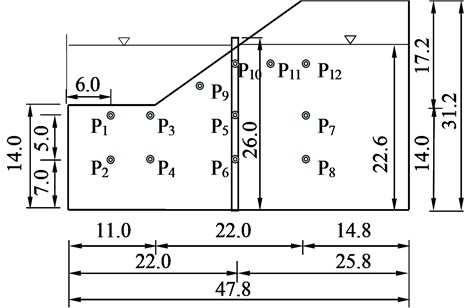
Fig. 2Layout of strain gauge of stabilizing pile
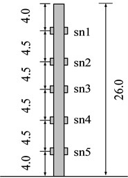
a) Model (unit: cm)
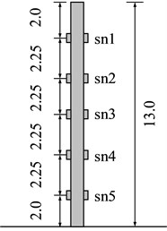
b) Prototype (unit: m)
Twelve porous pressure meters laid within the saturated foundation record the dynamic response of the excess pore pressure (EPP) of the saturated foundation in the different locations. The data given in Table 2 denote the peaks of the excess pore water pressure in the saturated foundation (P1 and P2), in the foundation near the slope toe (P3 and P4), in the foundation under the middle of the slope (P5 and P6), in the foundation under the slope crest (P7 and P8), and at the top of the slope below the water level (P9). This shows that the excess pore water pressure of the saturated foundation of the slope increases significantly and differently in different parts of the slope in the event of an earthquake. By estimating the pre-earthquake vertical effective normal stress of the measuring points and the measured peaks of the EPP induced by the earthquake of PPM and by deducting the effect of the soil weight on the pore water pressure meter due to the large deformation sliding of the slope, we can determine the excess pore pressure ratio of all the measuring points (Table 2). The effective stress on the right side of the slope is relatively large; therefore, the EPP ratio is considerably smaller than 1.0 (no liquefaction); however, the EPP ratio near the slope toe reaches 1.0, indicating that there is obvious liquefaction in the saturated subgrade near the slope toe.
Fig. 3Input seismic waves
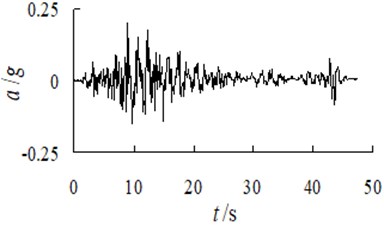
Table 2Excess pore pressure (EPP) and liquefaction
PPM | Peak of EPP(kPa) | Ratio of EPP | Liquefaction |
P1 | 19.3 | 1.00 | Yes |
P2 | 35.2 | 1.00 | Yes |
P3 | 26.3 | 1.00 | Yes |
P4 | 41.3 | 1.00 | Yes |
P5 | 43.1 | 0.75 | No |
P6 | 56.2 | 0.85 | No |
P7 | 51.4 | 0.55 | No |
P8 | 42.3 | 0.34 | No |
P9 | 11.4 | 1.00 | Yes |
P10 | 13.1 | 0.70 | No |
P11 | 10.5 | 0.22 | No |
P12 | 17.0 | 0.22 | No |
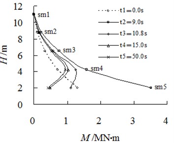
Strain gauges can measure the time history curve of the vertical strain (sn1-sn5) in the different positions of the stabilizing pile. According to the similar scale relations in Table 1 of the physical quantities such as the bending moment and the flexural stiffness, the strain time history can be converted into the total bending moment of the time history (sm1-sm5) of the corresponding location of the prototype stabilizing pile. To observe the changes in the bending moment of the pile, in this study, we measure the total static and dynamic bending moment according to the time history curve at 0.0 s (t1), 9.0 s (t2), 10.8 s (t3), 15.0 s (t4) and 50.0 s (t5) and draw the distribution of the bending moment along the elevation from t1 to t5, as shown in Fig. 4.
The total bending moment (sm5) corresponding to the strain gauge sn5 near the bottom of the pile from t1 to t5 is 1,300 kN·m, 3,512 kN·m, 1,017 kN·m, 485 kN·m and 422 kN·m. The bending moment of the pile from the top to the bottom at t1 is a nonlinear increasing static moment, and the bending moment distribution of the pile at this moment shows that no crack appears on the concrete piles under static conditions before an earthquake. The bending moment of the pile at t2 is the bending moment near the peak of an earthquake. Further, the bending moment value of the pile bottom (4,100 kN·m) can be calculated according to the distribution trend of the bending moment, and the value exceeds the ultimate bending moment (3,937 kN·m) of the prototype pile, indicating that there is a crack in the pile bottom. The total moment near the pile bottom from t3 to t5 point of time gradually decreases to close to zero because of the crack extension of the pile, indicating that there is pile breaking at the pile bottom. In fact, the pile end embedded constraint completely fails and gets converted into an active hinge constraint.
The pre-earthquake static bending moment at the pile bottom is 1,460 kN·m, and the total moment near the pile bottom caused by an earthquake is 4,100 kN·m. Therefore, the dynamic excess bending moment caused by the earthquake is 2,640 kN·m, which is equivalent to 180.8 % of the pre-earthquake static bending moment. Therefore, the dynamic excess bending moment caused by the foundation liquefaction and the slope sliding may be the main reason for the breaking of the stabilizing pile.
Fig. 4Distribution of moment of stabilizing piles
3. The generalized plastic constitutive model
The generalized plastic constitutive model of Pastor-Zienkiewicz III requires 13 parameters, which can be obtained through a conventional triaxial compression test under monotonic loading and cyclic loading conditions. The elastic relations are:
where Δεev and Δεes are the elastic volumetric strain increments and the deviatoric strain increments, respectively; Δp' and Δq are the elastic volumetric stress increments and the deviatoric stress increments, respectively; Kev and Ges are the elastic volumetric modulus and the shear modulus, respectively; p' is the mean effective stress, and Kevo, Keso and p0 are the parameters of the constitutive model.
The loading direction {ˉn} is defined as:
where q is the deviatoric stress, θ is the Lode angle df=(1+af)(Mf-η), η is the stress ratio and af is one of the parameters of the constitutive model. Mf is dependent on the Lode angle:
where Mfc is one of parameters of the constitutive model.
The plastic yielding function is defined as:
The corresponding plastic flow direction {ˉng} is:
where dg is the dilatancy law dg=(1+ag)(Mg-η), and ag is one of the parameters of the constitutive model. Mg is dependent on the Lode angle:
where Mgc is one of the parameters of the constitutive model.
The plastic potential function is defined as:
Chan developed the assistant SM2D program to simulate the soil triaxial test; the specific method for determining the model parameters is reported in the literature. The current study develops elastic-plastic dynamic true-coupled consolidation analysis software based on Zienkiewicz’s dynamic consolidation finite element method and the Pastor-Zienkiewicz III model. Characterized by the true coupling of dynamic consolidation and dynamic reaction, the developed software can calculate vibration, accumulation, diffusion and dissipation of pore water pressure throughout the entire process of vibration.
4. Numerical analyses of damage mechanism of stabilizing piles under liquefaction
On the basis of the dynamic consolidation finite element method developed by Zienkiewicz et al. and the Pastor-Zienkiewicz III model, in this study, we couple the dynamic consolidation with the dynamic response to develop the elastic-plastic dynamic consolidation analysis software FEMEPDYN, which can calculate the generation, diffusion and dissipation of the pore pressure during the entire vibration process, which can better reflect the actual state of the soil in the seismic process.
4.1. Numerical model
The linear elastic constitutive model is used for the reinforced concrete stabilizing pile; the concrete elastic modulus is 30 GPa, and Poisson’s ratio is 0.167. The data given in Table 3 are the corresponding model parameters of the Pastor-Zienkiewicz III model of Beijing White River fine sand.
By using symmetry to reduce the computational domain and taking into account the remote truncation boundary conditions, we build a prototype slope (Fig. 5) for a numerical calculation according to the test slope model shown in Fig. 1, and the corresponding three-dimensional finite element meshes are shown in Fig. 6. The elements considered are 8-node hexahedrons, the number of elements is 1396 and the number of nodes is 1268.
Table 3Parameters of pastor-zienkiewicz III model of white river sand
Parameter | Value | Unit |
Mfc | 0.95 | – |
Mgc | 1.5 | – |
af, ag | 0.45 | – |
Kevo | 7440 | kPa |
Keso | 14150 | kPa |
β0 | 1.0 | –- |
β1 | 0.1 | - |
H0 | 700 | – |
Hu0 | 1000 | kPa |
γ | 15 | – |
γu | 20 | – |
p0 | 100 | kPa |
The boundary conditions of the displacement are as follows: (1) the bottom is a fixed boundary; (2) the remote left-right lateral boundary is fixed; and (3) the normal displacement of the remaining two sides is set to zero in the horizontal direction.
The boundary conditions of the pore pressure are as follows: (1) the pore pressure of the node of the groundwater level is zero; (2) the bottom boundaries are impermeable boundaries; and (3) the four sides are impermeable boundaries.
The seismic waves considered in the numerical calculation are the input seismic waves considered in the test mentioned earlier (Fig. 3).
Fig. 5Prototype slope (Unit: m)
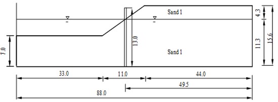
Fig. 6Three-Dimensional finite element meshes

4.2. Pore pressure and displacement analyses
The data illustrated in Fig. 7 show a comparison of the time history calculation with the test results of the EPP of the gauging points on the slope. Overall, the computational results are in good agreement with the time history of the EPP of the model tests. However, the computational peak is slightly smaller, while experimental values have a certain amount of noise. The values of the residual pore pressure are close at the later stage of the earthquake.
Fig. 7Comparison of EPP between test and computation

a) Pore pressure meter P1

b) Pore pressure meter P3
The comparison shows that the calculated value of the EPP P1 and P3 of the horizontal foundation in front of the slope increases slightly and slowly as compared to the measured value, but the pore pressure is basically the same at the later stage of the earthquake. In general, the calculated values are in good agreement with the experimental values. For the specific locations of P1 and P3, see Fig. 1.
Under the seismic action, the EPP of the saturated sand foundation increases significantly and differently in different parts. The EPP in the initial stage of the earthquake increases significantly and comes close to the peak quickly. The data illustrated in Fig. 8 show the EPP distribution of the slope at 45s during the earthquake. The figure shows that the EPP values of the saturated foundation at the toe of the slope and near the stabilizing pile are relatively large. As compared to the pre-earthquake effective stress, these results lead to the conclusion that there is a certain liquefied area near the toe of the slope, which is bound to have a significant impact on the slope stability and the stress response of the stabilizing pile.
Fig. 8Contour of EPP at 45 s during earthquake (unit: kPa)

The data illustrated in Fig. 9 show the horizontal displacement distribution of the corresponding prototype slope at the later stage of the earthquake. From this figure, we know that the sand liquefaction at the slope toe leads to a large deformation of the slope soil in front of the stabilizing pile. From the distribution of the deformation in the prototype slope, we observe that the large horizontal displacement at the slope toe and the slope top caused by the accumulation of the excess pore water pressure of the saturated foundation and the foundation liquefaction indicates that the earthquake liquefaction has a considerable impact on the deformation of slope.
The horizontal displacement of the soil at the lower part of the slope is approximately 0.6 m, and this deformation leads to the trend of the soil separating from the stabilizing pile at the lower part of the slope, leading to a decrease in the earth pressure in front of the stabilizing pile. The horizontal displacement of the seismic deformation at the slope top is approximately 0.3 m, and the soil at the upper part of the slope squeezes the pile because of the soil sliding trend at the slope top during the earthquake, resulting in an increase in the earth pressure at the back of the stabilizing pile during the earthquake. At the same time, the large displacement generates a significant motion interaction between the pile and the soil.
The dynamic finite element calculation not only verifies the results of the macroscopic deformation of the measuring points in the dynamic centrifuge modelling test but also effectively overcomes the shortcomings of the limited number of measuring points, gives the distribution of the slope displacement, and at the same time, illustrates that there is significant liquefaction at the saturated foundation according to the local large deformation displacement distribution.
Fig. 9Contour of horizontal displacement at 45s during earthquake (unit: m)

4.3. Crack failure mechanism analysis of stabilized piles
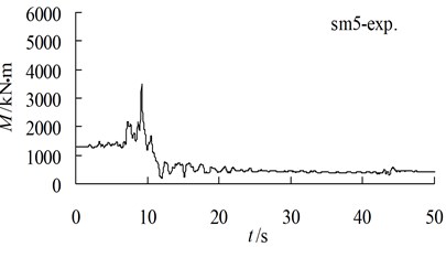
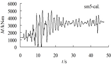
The data illustrated in Fig. 10 show a comparison of the total moment between the computation and the experiment near the pile bottom. The total static and dynamic bending moment corresponding to the strain gauge sn5 in the dynamic centrifuge modelling test are as follows: the static moment is 1,300 kN·m before the earthquake, the peak value of the static and dynamic bending moment is 3,512 kN·m, the dynamic excess moment is 2,212 kN·m and the relative amplification of the dynamic excess moment is 170.1 %. According to the distribution trend of the bending moment, the axis-pile bending moment distribution projections reveal the following: the static moment at the pile bottom is 1,460 kN·m before the earthquake, the total static and dynamic moment at the pile bottom caused by the earthquake is 4,100 kN·m, and the dynamic excess bending moment caused by the earthquake is 2,640 kN·m (equivalent to 180.8 % of the static moment before the earthquake). The static bending moment at the pile bottom obtained by the dynamic consolidation calculation is 1,324 kN·m. The peak value of the static and dynamic bending moment is 5,031 kN·m. The dynamic excess moment is 3,707 kN·m, and the relative amplification of the dynamic excess moment is 279.9 %. The dynamic residual moment is 2,112 kN·m, and the relative amplification of the residual dynamic excess moment is 159 %.
In the calculation of the dynamic consolidation, we use the elastic constitutive model for the reinforced concrete piles; therefore, the predicted dynamic excess moment of the stabilizing pile under an elastic condition in the event of an earthquake is larger than the experimentally obtained value. From Fig. 10, we observe that the total value of the static and dynamic moment at 9.0 s at the pile bottom under elastic conditions is 4,540 kN·m, which exceeds the ultimate bending strength (3,937 kN·m) of the stabilizing pile (Li et al., 2009). The comparison and judgment show that the results at the moment of the pile crack breaking obtained using the dynamic calculation and the centrifugal model test are in agreement (9.0 s during the earthquake).
Through the analyses of the pore pressure distribution in the foundation, the deformation distribution and the total value of the static and dynamic moment of the stabilizing pile, we conclude the dynamic damage mechanism of the stabilizing pile under high water conditions. The liquefaction of the saturated foundation leads to a large displacement at the slope toe and crest, and this leads to a decrease in the earth pressure in front of the stabilizing pile and an increase in the earth pressure behind the stabilizing pile, respectively. Furthermore, it leads to a significant increase in the dynamic excess moment of the stabilizing pile. Eventually, the total value of the static and dynamic moment of the stabilizing pile exceeds the ultimate bending moment and results in the crack damages, which is the main cause of the breaking of the stabilizing pile.
Fig. 10Comparison of bending moment near pile bottom between test and computation
a) History of bending moment in test
b) History of bending moment in computation
5. Conclusions
In order to simulate and analyze the dynamic breaking phenomena of a stabilizing model pile during earthquake liquefaction in the centrifuge modelling test, a developed stabilizing model pile made of the model concrete was used in a dynamic centrifuge modelling test according to meeting the strict similar scale between the model pile and the prototype stabilizing pile.
Through the test investigation and dynamic coupling numerical analyses, a conclusion can be drawn as follow: the deformation at the slope toe and crest caused by liquefaction leads to a decrease in the earth pressure in front of the stabilizing pile and an increase in the earth pressure behind the stabilizing pile; these effects eventually lead to the total bending moment becoming considerably larger than the static moment of the stabilizing pile and the large amplification of the dynamic excess bending moment, resulting in the stabilizing pile crack failure during a pile-soil motion interaction.
References
-
Erdik M., Şeşetyan K., Demircioğlu M. B., et al. Rapid earthquake loss assessment after damaging earthquakes. Soil Dynamics and Earthquake Engineering, Vol. 31, Issue 2, 2011, p. 247-266.
-
Neumayer E., Barthel F. Normalizing economic loss from natural disasters: a global analysis. Global Environmental Change, Vol. 21, Issue 1, 2011, p. 13-24.
-
Sun J., Wang L., Chen G. A probabilistic method to assess the regional susceptibility of landslides induced by earthquake in Kitakyushu City, Japan. Disaster Advances, Vol. 4, Issue 1, 2011, p. 7-18.
-
Jian W., Xu Q., Yang H., et al. Mechanism and failure process of Qianjiangping landslide in the Three Gorges Reservoir, China. Environmental Earth Sciences, Vol. 72, Issue 8, 2014, p. 2999-3013.
-
Meehan C. L., Vahedifard F. Evaluation of simplified methods for predicting earthquake-induced slope displacements in earth dams and embankments. Engineering Geology, Vol. 152, Issue 2, 2013, p. 180-193.
-
Ueng T. S. Shaking table tests for studies of soil liquefaction and soil-pile interaction. Geotechnical Engineering, Vol. 41, Issue 1, 2010, p. 29.
-
Kim M. K., Lee S. H., Choo Y. W., et al. Seismic behaviors of earth-core and concrete-faced rock-fill dams by dynamic centrifuge tests. Soil Dynamics and Earthquake Engineering, Vol. 31, Issue 11, 2011, p. 1579-1593.
-
Al-Defae A. H., Knappett J. A. Centrifuge modeling of the seismic performance of pile-reinforced slopes. Journal of Geotechnical and Geoenvironmental Engineering, Vol. 140, 6, p. 2014-4014014.
-
Yu Y., Deng L., Sun X., et al. Centrifuge modeling of dynamic behavior of pile-reinforced slopes during earthquakes. Journal of Central South University of Technology, Vol. 17, 2010, p. 1070-1078.
-
Knappett J. A., Reid C., Kinmond S., et al. Small-scale modeling of reinforced concrete structural elements for use in a geotechnical centrifuge. Journal of Structural Engineering, Vol. 137, Issue 11, 2010, p. 1263-1271.
-
Li R. J., Yan R., Li H. T. Experimental analyses of dynamic damage of the reinforced concrete pile. Applied Mechanics and Materials, Trans Tech Publications, Vol. 204, 2012, p. 3182-3185.
-
Wang D., Bienen B., Nazem M., et al. Large deformation finite element analyses in geotechnical engineering. Computers and Geotechnics, Vol. 65, 2015, p. 104-114.
-
Rezania M., Javadi A. A., Giustolisi O. Evaluation of liquefaction potential based on CPT results using evolutionary polynomial regression. Computers and Geotechnics, Vol. 37, Issue 1, 2010, p. 82-92.
About this article
This work was supported by the National Natural Science Foundation of China (Granted No. 11072193), the research Project of Shaanxi Provincial Key Laboratory of Loess Mechanics and Engineering (Granted No. 14JS064), and the Fundamental Research Funds for the Central Universities (Granted No. 2013G1502009).

