Abstract
For developing an active workpiece holder, piezo actuators are used to apply compensation forces and displacements. These actuators suffer from hysteresis effects which impair accuracy and performance. The focus of this work is the modelling of the actuator’s hysteresis and establishing a corresponding inverse model to compensate the effect in an open-loop approach. The model, on the basis of easy to calculate sigmoid functions, is shown to yield good linearization of the actuator’s behavior.
1. Introduction
Vibrations and chatter are common problems in milling processes and affect surface quality and productivity. Active workpiece holders are shown to offer effective countermeasures by compensating occurring vibration between work piece and tool [1]. The newly developed FixTronic advances existing approaches by establishing a new Linear Parameter-Varying Model (LPV-Model), which describes the changing workpiece dynamic during milling. Piezo actuators provide the necessary forces or displacements. However, they suffer from hysteretic effects. The goal is to examine, model and compensate hysteresis effects in order to ensure precise actuation conforming to the models calculation. A hysteresis model, formerly used for shape memory alloys, is adopted for the piezo actuator. The corresponding inverse model is then established to compensate the hysteresis in an open-loop inverse model based approach.
2. Hysteresis in piezoelectric actuators
Hysteresis effects are a common nonlinearity present in various smart materials such as ferroelectrics, magnetic materials, shape memory alloys or piezo electrics and thus, utilizing them in actuators is often challenging, especially piezo actuators, where the effect is quite prominent [2, 3]. Hystereses cause the output (e.g. displacement) to lag behind the input (e.g. voltage). This becomes important for dynamic applications like active vibration damping, since the sensitivity to the control signal is negatively affected [4].
Hysteresis models can be classified into physical-based and phenomenological. While the first type allows further understanding of the underlying effects, the latter is generally preferred for real application because of lesser complexity [2].
A prominent example is the Preisach model, originally developed to describe magnetization. However, the model proved useful for hysteretic effects in general and was used in numerous applications. Although the model is shown to yield highly accurate results, parameterization is challenging and it demands quite intensive processing [2, 5-7].
Another type of hysteresis models use simple mathematical functions, e.g. the sigmoid function. They are shown to yield good results and are easy to calculate, which makes them favorable for high dynamic applications. The following section presents such a model which is designed to model and compensate the hysteresis of a piezo actuator.
3. Sigmoid-based hysteresis model
Sigmoid functions exhibit an ‘S’-shaped curve with a pair of horizontal asymptotes and have been used to describe processes in numerous research fields, often with modifications to take into account specific effects [5, 8, 9]. Corresponding inverse models were developed and successfully used to compensate the nonlinearities [7, 10].
The approach in this work is similar to [7]. A forward model based on asymmetric sigmoid functions is used to model the piezo actuator’s hysteresis. It is capable of describing major and minor loops. Then an inverse model is established in an open-loop approach to compensate the hysteresis behavior. The forward models’ parameters are optimized for good correlation with experimental data and hold for the inverse as well. For further details, please refer to [7].
3.1. Forward model
In the given approach, a full loop comprises two asymmetric sigmoid curves. The basic formula is given by Eq. (1). Here, index indicates the upward curve while index indicates parameters of the downward curve. Correspondingly, index holds for rising input values and index for decreasing inputs :
is a dimensionless value with 0 1. It can directly be interpreted as the actuators displacement with the linear correlation , where 0.06 mm, while the upper and lower bounds coincide with the min. and max. displacement of the piezo. The shape of the curve is defined by a set of parameters: While , hold for every ‘up’ or ‘down’ curve respectively, parameters and are calculated individually. When the direction of the input signal changes, there is a switch from an upward branch to a downward branch or vice versa and all parameters are updated.
When switching from ‘up’ to ‘down’ the parameters are updated according to Eq. (2), (3):
In the opposite case, when switching from “down” to “up”, Eq. (4), (5) hold:
Here, and are the values of the previous time step before updating. The model parameters are chosen to match data obtained from measurement, see section 4 and 5, and are given in Table 1.
Table 1Model parameters
/ µm | / V | / V | / µm |
4.6 | 480 | –90 | 0.0036 |
3.2. Inverse model
The inverse of the forward model is given by Eq. (6):
Again, index indicates upward curves (rising ) and index indicates downward curves (decreasing ). In the same manner as for the forward model, parameters are updated whenever the input signal changes direction, hence Eqs. (2)-(5) hold.
The obtained inverse model correlates with the forward model, see Fig. 1, and should linearize the systems behavior, as long as the forward model matches the measured hysteresis. This is evaluated with measurements addressed in the following paragraph.
Fig. 1Inverse model, forward model and linearization

4. Measurement setup
The measurement setup, shown in Fig. 2, is designed to measure the displacement of the actor when applying voltage as an input signal.
Fig. 2Photograph of measurement setup

It comprises the elements given in Table 2. The piezo actuator (max. voltage = 1 kV, max. displacement = 60 µm) is clamped on one side and may expand and contract freely, i.e. with no outer force applied. The piezo amplifier adds a constant voltage to the control voltage to set a working point. By this, the piezo is allowed to exhibit displacement in both directions. For the experiments though, the set point 0 V is chosen to allow for large hysteresis loops in one direction. The vibrometer is calibrated to measure displacements from this set point. The developed hysteresis model is realized within Matlab/Simulink.
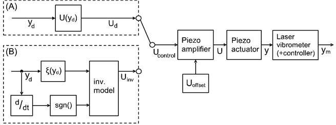
In the scope of this study, two kinds of experiments are carried out. The setup and control scheme is illustrated in Fig. 3. For identifying the hysteresis of the actuator and to parameterize the forward model, configuration (A) is used, where the desired displacement is linearly approximated into a desired control signal . When evaluating the inverse model compensation, configuration (B) is employed, where equals the reshaped input signal for the piezo (i.e. amplifier) to yield a more linear relation between voltage applied and displacement of the actuator. The approach is open-loop, which means there is no feedback necessary. This simplifies or even enables the usage in later application since there are no means for measuring the actuators displacement directly within the final clamping device for active vibration cancellation.
Table 2Test bench equipment
Piece of equipment | Type | Manufacturer |
Piezoelectric actuator | P-225.40 | Physik instrumente GmbH & Co. KG |
Piezo amplifier | E-481 | |
Laser vibrometer sensor head | OFV-534 | Polytec GmbH |
Laser vibrometer controller | OFV-5000 | |
Simulation software | Matlab / Simulink 2015b | Mathworks Inc. |
Real-time target machine | Speedgoat | Speedgoat GmbH |
Fig. 3Control scheme and measurement setup
5. Hysteresis identification and forward model
The focus lies on the identification of the hysteresis exhibited by the piezo. Thus, one has to prevent other effects from contributing to the measurements, since it is not possible to distinguish between nonlinearity caused by hysteresis or other influences, such as negative phase of the plant or possible delays caused by the measurement system [2, 11]. As pointed out by [6], the hysteresis itself does not depend on frequency, so in order to safely avoid other effects, input signals only span 5 Hz to 40 Hz. In even smaller frequency ranges, creeping of the piezo would interfere [6]. It shall be noted though, that there is no common consent regarding frequency dependence [11]. However, the influence is minor and experiments in this work have shown that avoiding the aforementioned parasitic effects in measurements is more important.
When identifying the hysteresis, it is not sufficient to measure the major loop. It is vital to cover a wide range of minor loops too. Therefore, a sinusoidal input signal with rising amplitude is chosen to cover a large number of minor loops, which are homogeneously distributed.
Fig. 4 illustrates one measurement with input signal over time and the measured actuators displacement over input voltage . The hysteresis conforms findings of [4, 6]. Results substantiate that the hysteresis’ width much more depends on amplitude than on frequency. A small shift of the working point after each loop can be observed, the so-called wipe-out, reported by [4]. Since the effect is rather negligible, it is not taken into account, i.e. not compensated.
6. Experimental validation of forward model and open-loop compensation
Measurements are carried out with input frequencies between 5 Hz and 40 Hz and rising voltages up to 800 V. The forward model is parameterized to match these curves. Values are given in Table 1. Fig. 5 shows the good congruency between real system and forward model. For the sake of clarity, only five loops are displayed. Table 3 gives the root-mean-square tracking error (RMSTE) between forward model and measurement. It also provides the normalized RMSTE (NRMSTE) with respect to the measurement range.
Fig. 4Hysteresis measurement
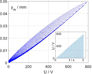
Fig. 5Measurement and forward model
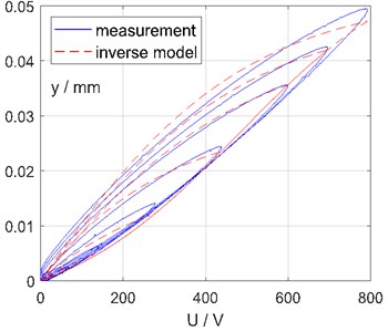
The model shows some deviation, especially for small loops. Since the hysteresis effect is much more significant for larger loops, model parameters are chosen to fit best for those and a poorer match for smaller loops is accepted knowingly.
Finally, Fig. 6, 7 show the result of the open-loop inverse model compensation. As can be seen, a clear benefit arises and the relation between input voltage and measured displacement is significantly more linear.
Fig. 6Linearization with hysteresis compensation
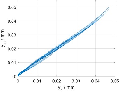
Fig. 7Benefit with compensation
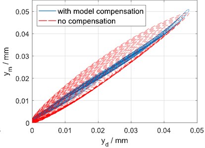
Table 3Experiments and tracking errors
Experiment | 1 | 2 | 3 | 4 | 5 | 6 | 7 | 8 |
Voltage / V | 0…800 | |||||||
Frequency / Hz | 5 | 5 | 10 | 10 | 20 | 20 | 40 | 40 |
Number of cycles | 25 | 50 | 25 | 50 | 50 | 100 | 75 | 150 |
RMSTE / µm | 1.4 | 1.4 | 1.2 | 1.1 | 0.8 | 0.9 | 1.6 | 1.6 |
NRMSTE / % | 3.0 | 2.9 | 2.4 | 2.2 | 1.8 | 1.9 | 3.2 | 3.1 |
7. Conclusions
This work presented an open-loop, model based approach for compensating hysteretic effects of a piezo actuator. The easy to calculate model based on sigmoid functions was briefly introduced. Measurements identified the hysteresis and showed good correlation with the forward model. The inverse model was able to successfully compensate the actuators hysteresis. The approach is expected to improve the actuation of the FixTronic, an active workpiece holder for active vibration damping. For the future, the approach will be advanced aiming for higher accuracy for a large set of working conditions.
References
-
Brecher C., Manoharan D., Ladra U., Köpken H.-G. Chatter suppression with an active workpiece holder. Production Engineering Research and Development, Vol. 4, Issues 2-3, 2010, p. 239-245.
-
Mayergoyz I., Bertotti G.,Damjanovic D. Hysteresis in Piezoelectric and Ferroelectric Materials. The Science of Hysteresis, Volume 3, Elsevier, St. Louis, 2005.
-
Stakvik J. Å., Ragazzon M. R. P., Eielsen A. A., Gravdahl J. T. On implementation of the Preisach model identification and inversion for hysteresis compensation. Modeling, Identification and Control, Vol. 36, Issue 3, 2015, p. 133-142.
-
Rodriguez-Fortun J. M., Orus J., Alfonso J., Buil F., Castellanos J. A. Hysteresis in piezoelectric actuators: modeling and compensation. Proceedings of the 18th World Congress of the International Federation of Automatic Control, Milano, Italy, 2011.
-
Petrescu L., Cazacu E., Petrescu C. Sigmoid functions used in hysteresis phenomenon modeling. The 9th International Symposium on Advanced Topics in Electrical Engineering, Bucharest (Romania), 2015, p. 521-524.
-
Stakvik J. Å. Identification, Inversion and Implementation of the Preisach Hysteresis Model in Nanopositioning. Master’s Thesis, Norwegian University of Science and Technology, 2014.
-
Pai A., Riepold M., Trächtler A. Model-based precision position and force control of SMA actuators with a clamping application. Mechatronics, Vol. 50, 2018, p. 303-320.
-
Wang E. R., Ma X. Q., Rakhela S., Su C. Y. Modelling the hysteretic characteristics of a magnetorheological fluid damper. Proceedings of the Institution of Mechanical Engineers, Part D: Journal of Automobile Engineering, Vol. 217, 2003, p. 537-550.
-
Madill D. R., Wang D. Modeling and L2-stabilty of a shape memory alloy position control system. IEEE Transactions on Control Systems Technology, Vol. 6, Issue 4, 1998, p. 473-481.
-
Zhang J., Yin Y., Zhu J. Sigmoid-based hysteresis modeling and high-speed tracking control of SMA-artificial muscle. Sensors and Actuators A, Vol. 201, 2013, p. 264-273.
-
Schreier V. Automated Parameter Identification and Controller Optimization for Piezoelectric Actuators. Master’s Thesis, Universität Paderborn, 2014, (in German).
Cited by
About this article
The authors gratefully acknowledge funding by Projektträger Jülich, under financial support of the European Union (European Regional Development Fund, EFRE) and the German State of North Rhine-Westphalia in the context of the initiative “Investment for Growth and Employment”.
