Abstract
Wheel vibration is one of the most crucial factors associated with the running safety of a train. How to detect and estimate it in real-time attracts significantly researchers’ interest recently? In this paper, a new method of estimating the wheel vibration of a railway vehicle utilizing a partial state observer is proposed. The partial state observer of wheel vibration estimation is designed based on the railway vehicle dynamic system model established in state space. Different kinds of track irregularities are considered as inputs for the vehicle dynamic system. Subsequently, the state responses of the car-body and the bogie frame obtained from dynamic simulation are used as the inputs of the partial state observer. The simulations were conducted at various running speeds of a vehicle. The results show that the partial state observer is capable of estimating well the wheel vibration using dynamic responses of the car-body and the bogie frame, and has a stable convergence, which leads to get consistent with the real dynamic system after duration of 0.15 s from starting system. This method thus would provide an innovative approach to estimate the wheel vibration of a real railway vehicle in real-time.
1. Introduction
Wheel vibrations of a railway vehicle are crucial to the running safety and ride comfort of a train. Thus, their features are usually used for fault diagnosis of the wheelset and the track structure [1]. Currently the main way to obtain the wheel vibration information is to measure indirectly the vibration of axle boxes applying acceleration sensors, resulting in poor accuracy, some potential safe problems and extra costs. Recently, many researchers have been interested in estimation of the related vibration parameters of wheelsets. Zi-li Li et al. utilized the vibration of wheelset to detect the short wave of rail [1]. Fujia Xia et al. transformed the vehicle dynamic system, according to the relationship between the wheel vibration and wheel-rail contact force, from the differential equations into the state space and calculated the wheel-rail contact force combined with parameter estimation [2]. In addition, Wei wei et al. utilized wheel vibration and finite element method to build the noise model of a wheelset, and obtained the displacement of vibration at the contacted points between rail and wheelset, and then turned the displacement into velocity which was eventually used to analyze the sound source and its features [3]. D. J. Thompson et al. built a hybrid model in the time domain, and used it to analyze the reason of ground vibration caused by an irregularity and a moving static load [4].
Since the state of the vehicle body and the frame is relatively easy and safe to be obtained using sensors, such as accelerometer, displacement meter and inclinometer, it’s potentially an effective method to get indirectly the wheel vibration by measuring the vibration of car-body and bogie frame. In some practical engineering field, State observer technology has already been used to obtain state variables in a moving mechanism that can’t be directly or easily measured. For example, by building an automobile steering mechanism and tire ground contact model, the researcher established a state observer to get the nonlinear force of automobile tires utilizing some parameters as inputs, including the center of mass deflection angle, steering input angle and ground excitation [5]. And also a certain kind of state observer was designed to estimate the state and input of a class of uncertain system [6].
In this paper, we designed a partial-state observer based on Lyapunov stability theory to estimate the wheel vibration of a railway vehicle utilizing the vibrations of car-body and bogie frame. It is organized in 5 sections as following. In Section 1, we reviewed some research work about the estimation of wheel vibration. In Section 2, we built a vertical vehicle dynamic system model in differential equations and transferred them into the state space. Then, we solve the linear matrix inequality based on LMI method to get its feedback matrix and estimate wheel vibration based on the dynamic system model in Section 3. In Section 4, simulations of the vehicle dynamic system were conducted at various running speeds, and the observer was used to obtain the vibration of wheel and meanwhile its performance was analyzed as well. Finally, we come to some conclusions in Section 5.
2. Modelling the vehicle dynamic system
A vertical vehicle dynamic system can be usually used to study some behaviors of a running vehicle. Here we built the vertical vehicle dynamic system model, as shown in Fig. 1, to study the wheel vibration and to design the corresponding state observer.
Fig. 1The vertical vehicle dynamic system model
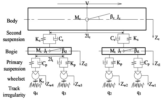
Assuming that the stiffness and damping of the primary suspension are equal to the sum of the stiffness and damping of spring on each bogie axle box respectively, and similarly, the stiffness and damping of the secondary suspension are the sum of the stiffness and damping of each spring between car-body and bogie. The vehicle vertical dynamic system was built with 10 DOFs. The car-body has 2 DOFs (heaving , pitching ). Each bogie has 2 DOFs (heaving , pitching ) and each wheelset has 1 DOF (heaving ), , and are the masses of car-body, bogie and wheelsets respectively. and are the moment of inertia of the car-body and bogie regarding to pitching. and represent the primary and secondary vertical damping respectively; and stand for the primary and secondary vertical stiffness. Let be a half length of the car-body, and be a half length of the wheelbase. , and represent respectively the vertical displacement of car-body, bogie and wheelset. and are the pitching angular of car-body and bogie. is track irregularity used as the input for the dynamic system ( 1-4).
The vertical vibration differential equations of vehicle can be written according to kinematics, shown as Eq. (1) to (10).
1) Heaving motion of the car-body:
2) Pitching motion of the car-body:
3) Heaving motion of the front bogie frame:
4) Pitching motion of the front bogie frame:
5) Heaving motion of the rear bogie frame:
6) Pitching motion of the rear bogie frame:
7) Heaving motion of the first wheel set:
8) Heaving motion of the second wheelset:
9) Heaving motion of the third wheelset:
10) Heaving motion of the fourth wheelset:
Let be a state vector:
Transform differential Eqs. (1-10) above to the form of state-space:
where, is the character matrix including mass, stiffness and damping of the vehicle dynamic system.
Now, having linearized the function , we can obtain Eq. (12) from the Eq. (11) [6]:
where, is the coefficient matrix of the wheelsets’ mass, linear stiffness and the generalized load.
3. State observer design
Although wheel vibrations are difficult to measure directly, vibrations of the car-body and the bogie frame are easy to obtain by utilizing sensors. Consequently, we tried to design a partial state observer to obtain the wheelset vibrations utilizing the vibrations of car-body and bogie frame based on the dynamic system. In this paper, thus, an observer was designed to obtain the displacement of wheelset with inputs of the vibrations of car-body and bogie frame.
The key to designing a state observer is to get its feedback matrix, which is a significant factor for the state-observer performance, deciding the convergence rate of the state. Currently, there are several well-designed algorithms of a state observer feedback matrix, including synovial control algorithm, Kalman filter algorithm, Pole Placement Method and etc. In this paper, the wheel-rail force was linearized, so that the feedback matrix was further designed based on the Lyapunov stability theory. Here we also utilized the matrix inequality LMI (linear matrix inequality) tools to get the corresponding coefficient matrix of the partial state observer.
The partial state observer can be described as Eq. (13):
where, is a state vector of the car-body and bogie frame, andis a state vector of the displacement of wheelset:
where is an output matrix of accelerations of car-body and bogie frame. And is an output matrix of the vibration displacement of wheelset.
Let , as we know, is supposed to be full-rank if the system is controllable [7]. Here, thus, we have , and is controllable. We also have , and .
The partial state observer for the system can be got as the following Eq. (13) [6, 7]:
where matrices , , and are to be determined, which make converge asymptotically to .
Let be a full-row rank matrix, and be the state estimation error, and be the error vector, we have:
According to Eq. (13), (14) and (15), the error dynamics equations can be obtained as follow:
Moreover, the error vector can be expressed as:
We have and as if the following requirement, shown as Eq. (18), is met:
If we want the designed partial state observer to converge fast the real state of system, there should exist matrices and such that the following linear matrix should be required, shown as Eq. (19), according to Lyapunov stability theory [8]:
where and denote the generalized inverse matrices of and respectively. The matrices and can be obtained utilizing the LMI tools. Furthermore, matrices , , and of the observer, described as Eq. (14) are then determined as:
4. Simulation and analysis
IMU (Inertial Measurement Unit) is usually used to measure the motion state of mechanism. We can use a number of IMU to obtain the state of car-body and bogie frame of a railway vehicle, as shown in Fig. 2.
As we discussed in Section 2 and 3, we built the partial state observer regarding to the vehicle dynamic system. In this simulation experiment, the outputs of the car-body and bogie frame were input into the state observer to estimate the wheel vibrations, and the estimated vibrations were then compared with the calculated value from the vehicle dynamic system to further find out the performance of the state observer. Moreover, a track irregularity is added to the system simultaneously, as shown in Fig. 3.
We conducted the dynamic simulations regarding the rail as rigid body, i.e. regardless of the rail dynamic irregularities caused by the load of wheel-rail. As we know that the measuring data contain noises, so in order to learn the performance of the observer, we added 0.5 % of the measurement noise in the simulations, for a real observer is generally interfered by external noise. We discrete the continuous Eq. (14) [8, 9] due to the computer processing with the discrete step 10-3 s, taking into account that the frequency of wheel-rail force is generally 5 KHz [10]. The dynamic parameters of a railway vehicle for the simulations are list in Table 1.
Fig. 2Parameters of measured and observed
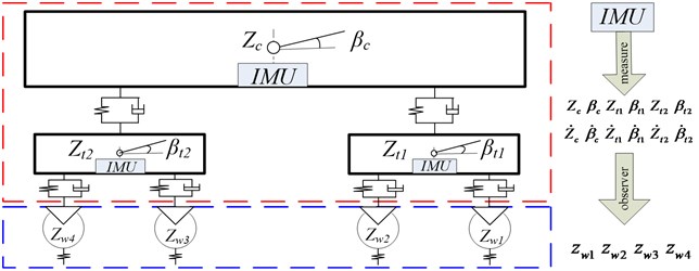
Fig. 3Flow chart of the simulation experiments
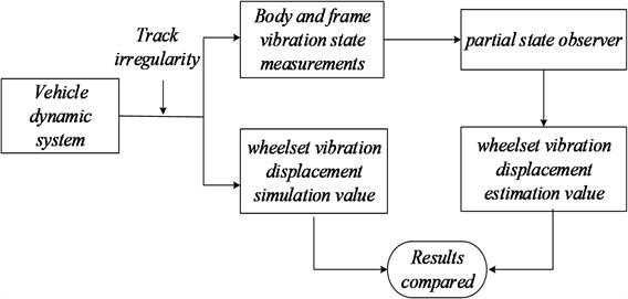
Table 1Railway passenger vehicle parameters
Parameter | Unit | Value |
Mass of body | kg | 38500 |
Mass of bogie | kg | 2980 |
Mass of wheelset | kg | 1350 |
Inertia body nod | kg·m2 | 2.446×e6 |
Inertia bogie nod | kg·m2 | 3605 |
Primary suspension stiffness | N/m | 2.14×e6 |
Second suspension stiffness | N/m | 2.535×e6 |
Primary suspension damping | N·s/m | 4.9×e4 |
Second suspension damping | N·s/m | 1.96×e5 |
Half length of the vehicle | m | 8.4 |
Half length of the bogie | m | 1.2 |
Wheel radius | m | 0.4575 |
Acceleration of gravity | m/s-2 | 9.8 |
Linear stiffness | N/m | (1.5/G)×P01/3 |
Track spectrum is used to simulate the track irregularities which are the excitation for a running vehicle. There are several track spectrums utilized in computer simulation, including European track grade spectrum, U.S. track grade spectrum and China three major tracks line spectrum [11]. Here we used the U.S. five-grade track spectrum as the track irregularity PSD (power spectrum density). The PSD function was normally transformed into the time domain by applying inverse Fourier transform. Fig. 4 shows the vertical track irregularity for the simulations.
In order to study the feasibility of the designed observer for estimating the wheel vibrations, its corresponding state estimation error and convergence performance to be assessed. Therefore, we conducted the simulations with different running speed levels of vehicle at 60 km/h, 80 km/hand 120 km/h. The sample interval is considered as 0.001 second and simulation time length is 8 second. According to the vehicle dynamic theory, wheelsets from one frame have the similar dynamic properties, so Figs. 5, 6 and 7 show the vibration displacements of wheelset 1 and wheelset 3, Figs. 8, 9 and 10 show the corresponding estimation results of the observer and the convergence time.
Fig. 4The vertical track irregularity
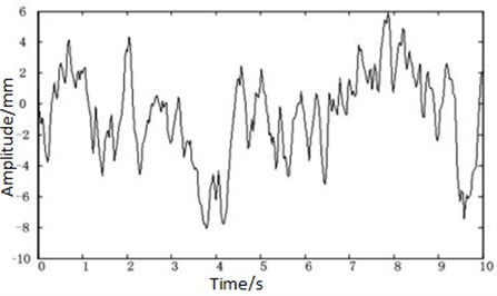
Fig. 5Displacement of the wheel of the observer at speed V= 60 km/s
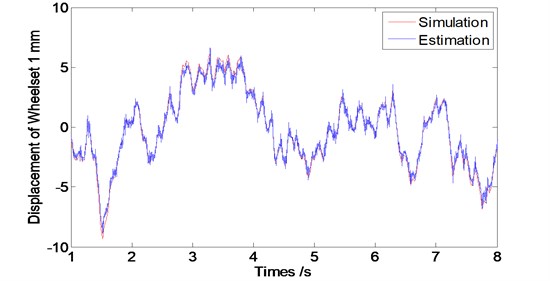
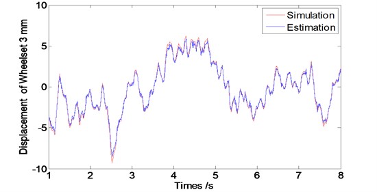
As we can see from Figs. 5 to 7 that the designed observer can realize the estimation of wheelset vibration displacement under different conditions of running speed levels. Estimations of the wheelset vibrations from the observer are tending to be consistent with the results from the dynamic system simulations as operation time goes by. The tracking property becomes worse slightly along with the train speed increasing (The oscillating amplitude of estimated values enlarges as the train speed increases).
Fig. 6Displacement of the wheel of the observer at speed V= 80 km/s
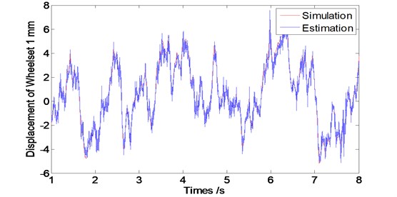
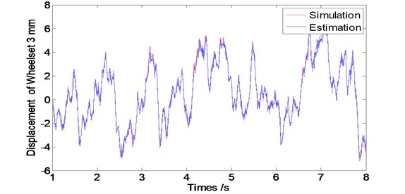
Fig. 7Displacement of the wheel of the observer at speed V= 120 km/s
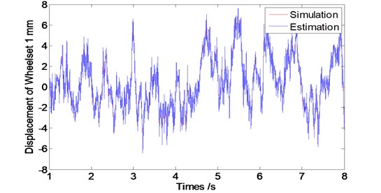
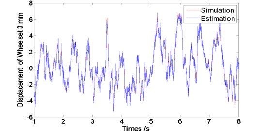
Fig. 8Convergence time of the observer at speed V= 60 km/s
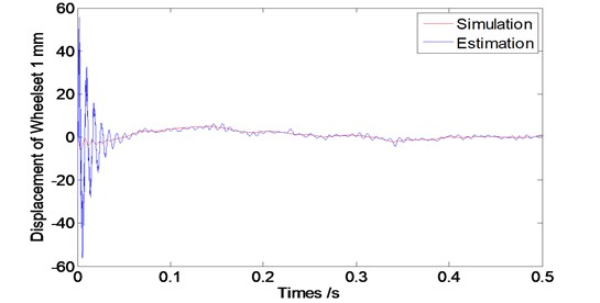
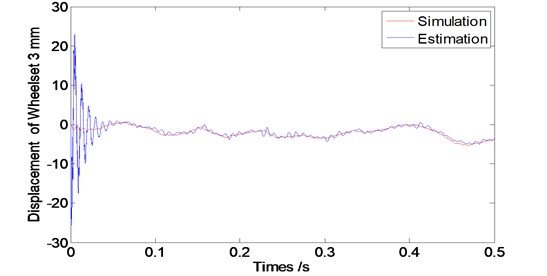
Fig. 9Convergence time of the observer at speed V= 80 km/s
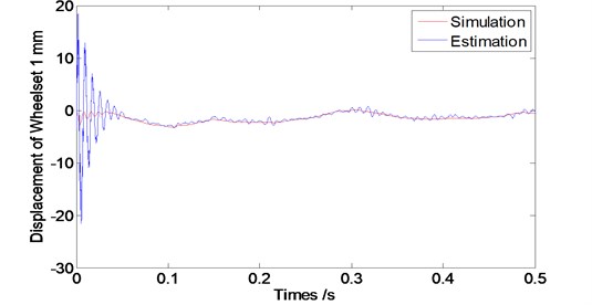
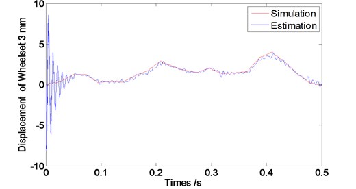
From Fig. 8 to 10, we can see that the designed observer has an effective performance of convergence with the short convergence time of about 0.15 s. Moreover, as the train speed increases, the convergence time extends slightly, which shows that the designed observer is stable.
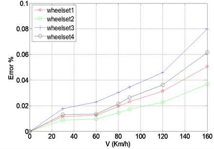
Meanwhile, the max errors between the estimated values and simulation values enlarge along with the increase of train speed after starting 1 second when the observer become stable, as shown in Fig. 11.
From the Fig. 11, we also find that the average errors are still in a small range, even if the biggest average error is less than 0.1 % at the speed of 160 km/h though.
Fig. 10Convergence time of the observer at speed V= 120 km/s
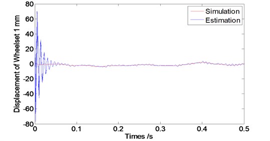
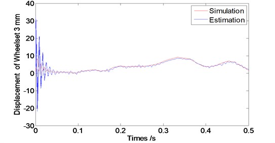
Fig. 11Max errors between the estimation and the system simulations of wheel vibration at different running speed after 1 s
5. Conclusions
Wheel vibrations are important factors associated with the running safety of a railway vehicle and hard to measurement directly. We designed a partial state observer to estimate it easily utilizing the vibrations of car-body and bogie frame. And the vertical vehicle dynamic system model was built and simulated with the track irregularity as excitation to product the corresponding vibrations, and thus, to validate the feasibility of the observer, as well as the observer performances of estimation errors and convergence time. We come to the conclusions that the designed observer is consistent well with the vehicle dynamic system with a short convergence time and a small error, and it would be a new effective method of estimating the wheel vibrations.
References
-
Molodova Marija, Li Z. L., Dollevoet Rolf Axle box acceleration: measurement and simulation for detection of short track defects. Wear, Vol. 271, 2011, p. 349-356.
-
Xia F. J., Cole C. L., Wolfs Peter Grey box-based inverse wagon model to predict wheel-rail contact forces from measured wagon body responses. Vehicle System Dynamics, Vol. 46, 2008, p. 469-479.
-
Wei W., Zhao X. G. Analysis on vibration and noise of vehicle wheel. Noise and Vibration Control, Vol. 4, 2007, p. 99-102.
-
Triepaischajonsak N., Thompson D. J. A hybrid modeling approach for predicting ground vibration from trains. Journal of Sound and Vibration, Vol. 335, 2015, p. 147-173.
-
Su H. T. Research on the Methods of Vehicle Nonlinear Tyre Orces Estimation. Jilin University Master Degree Dissertation, 2007.
-
Corless Martin, Tu Jay State and input estimation for a class of uncertain systems. Automatic, Vol. 34, 1988, p. 757-764.
-
Trinh H., Fernando T., Nahavandi S. Partial-state observers for nonlinear systems. IEEE Transactions on Automatic Control, Vol. 51, 2006, p. 1808-1812.
-
Zhai W. M. Vehicle-Track Coupling Dynamics (3rd Edition). Science Press, Beijing, 2006.
-
Phanomchoeng G., Rajamani R. Observer design for Lipschitz nonlinear systems using Riccati equations. American Control Conference, Marriott Waterfront, Baltimore, MD, USA, 2010.
-
Fang Y., Chen L., Zheng S. B., Zhang G. F. Condition monitoring of rail vehicle suspension system based on parameter estimation. Journal of the China Railway Society, Vol. 35, Issue 5, 2013, p. 15-20.
-
Chen G., Zhai W. M. Numerical simulation of the stochastic processes of railway track irregularities. Journal of Southwest Jiao Tong University, Vol. 4, Issue 2, 1994, p. 138-142.
About this article
This work is supported by National Natural Science Foundation of China (Grant No. 51478258), Shanghai Municipal Natural Science Foundation (Grant No. 12ZR1412300), Key Technology R&D Project of Shanghai Committee of Science and Technology (Grant No. 13510501300) and Construction Project for Transportation Engineering (Grant No. 13SC002).
