Abstract
A hydraulic shaking table has obvious frictional characteristics that will result in the deterioration of test waveforms and affect test accuracy. In this study, the influence of nonlinear friction for a hydraulic shaking table test system is analyzed briefly. For dynamic friction parameters and unknown system load characteristics, a mathematical model is developed based on the LuGre friction model, and double nonlinear observers are constructed to estimate average deflection. A backstepping integral control method is proposed to compensate the nonlinear friction and estimate the unknown load disturbances. The stability of the closed-loop system is proved by the Lyapunov function. In the test, an iterative control algorithm is utilized to obtain the system inverse transfer function. The experimental results show that the proposed method can reduce the nonlinear friction of the hydraulic servo system, and improve the control accuracy of the hydraulic shaking table. In addition, high identification accuracy for system impedance is also achieved. Compared to no friction compensating method, the acceleration waveform distortion is reduced from 19 % to 5 % and the peak error is reduced from 14 % to 4.2 % by the proposed method, and the deviation of power spectral density is also reduced effectively.
1. Introduction
A hydraulic shaking table is a typical hydraulic servo system with advantages such as a lower frequency limit and higher shaking force. They are widely used in civil engineering, transportation, environmental simulation, and other fields [1, 2]. Compared to an electro-magnetic excitation shaker, the hydraulic shaking table has a stronger nonlinear characteristic. One of the major nonlinear characteristic arises from the hydraulic cylinder friction [3]. The nonlinear friction has a time-varying characteristic and becomes a main source of interference for the hydraulic servo system, which often causes steady-state error, limit cycle, and slow speed issues of the system [4, 5]. In actual production applications, there are inevitable internal parameters and external load force uncertainties that significantly affect the dynamic performance of the system. In order to improve low-speed stability and position-tracking accuracy for the servo system during the test, a reasonable compensation method has to be used to reduce or eliminate the impact of nonlinear friction on the system.
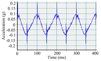
At present, a majority of hydraulic shaking tables use seal-type hydraulic cylinders. Because of the seals, some friction is generated inside the hydraulic cylinder. As the amplitude of the shaking test is usually small, the friction will have a great effect on the shaking simulation precision [6]. Fig. 1 shows a low-level acceleration control waveform of the hydraulic cylinder under a proportional-integral-derivative (PID) control mode with very hard seals in the hydraulic cylinder. Looking at the figure, the distortion of acceleration wave is quite high because of the friction variation on the hydraulic cylinder commutation (peak acceleration).
Except for traditionally adding flutter signals to the control signals and increasing the open-loop gain, there are two methods for reducing the system friction at present [2, 7]: one method is to increase the robustness of the system such as using a fuzzy controller, variable gain compensation, and disturbance observer methods; the other method is to use a friction model to identify system parameters and design a compensator to overcome the friction. The first control method has a more complex control algorithm with many uncertainties. The second control method is relatively simple to implement, but requires precision parameters for identification.
Fig. 1Effect of friction on the acceleration waveform of the servo-hydraulic cylinder
Therefore, the identification and compensation of friction for the servo system are the main focus of the study [8, 9]. For these problems, many local and international researchers have used a variety of methods to compensate the friction of the servo system such as adaptive control and sliding mode control, fuzzy control [10, 11]. Practices show that the use of the dynamic friction LuGre model to construct a closed-loop state observer can effectively estimate the state variable of friction. It can reduce the system nonlinear characteristics and be easily applied to the control system design. The adverse effects of friction on the electro-mechanical servo system are identified online. To some extent, the traditional friction processing method may compensate for the friction losses. The adaptive control algorithm has obvious advantages of parameter self-tuning for friction compensation, but which overly relies on the accuracy of the friction model. For the sensor noise interferences, the high gain causes the system robustness to decline. In [12], a nonlinear observer based on backstepping integral is used to achieve an adaptive compensation of frictional torque. However, it is only applicable to the simulation analysis, but not to the actual project. In [13], the kinetic model of the open servo system is built to design an adaptive friction compensation controller by using backstepping. In [14], the robust H∞ controller is designed to reduce uncertainty parameters for the electro-hydraulic servo position system and ensure the system stability. In [15], a feed-forward compensator and a zero phase error tracking controller are used to improve the accuracy of the inverse transfer function for the electro-hydraulic shaking table. In [16], an adaptive fuzzy backstepping control is adopted, but the use of backstepping integral control method in hydraulic shaking table system is rare.
In this study, a backstepping integral control method is adopted to design the controller of the hydraulic shaking table based on the LuGre friction model. Aiming for nonlinear friction and uncertain parameters, the virtual control variables are designed to estimate the deflection of bristles of the LuGre model, and realize the system adaptive compensations from the nonlinear friction and load disturbances uncertainty. Using two different test methods, the system impedance and inverse transfer function are identified. Both the acceleration waveform distortion and the peak error are reduced effectively.
2. Structure of servo system
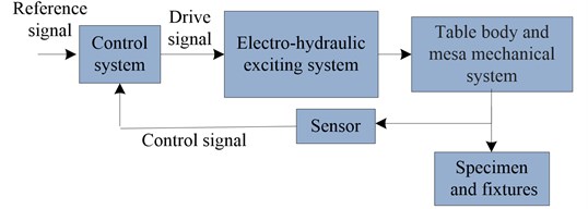
The shaking test table is a complex electro-hydraulic servo system, which is composed mainly of an electro-hydraulic system excitation, table body and mesa mechanical system, and sensors and control system. Specimens are mounted on the shaking table, which are excited by the electro-hydraulic system excitation. The acceleration control and displacement control signals from shaking control points are collected by sensors, which serve as feedback to the control system. The requirement of earthquake simulation test is to recurrent the acceleration time-domain signal. In the servo control system, the displacement signal of the shaking table is measured by the displacement sensors. A linear variable differential transformer can get better linear and frictionless displacement signal. The drive signals of the shaking simulation test system are calculated based on the control signal and reference signal. The control strategy can enable the system to achieve a shaking simulation test at higher accuracy. The block diagram of the shaking test system is shown in Fig. 2.
Fig. 2Block diagram of the shaking test system
3. Friction compensation based on the LuGre model
3.1. LuGre friction model
The friction model can be divided into static and dynamic models. Previous studies showed that the static friction model has low accuracy, whereas the LuGre dynamic friction model can accurately describe the friction phenomenon of the mechanical movement [17–21].
In Fig. 4, the LuGre model assumes that the contact surface is microscopic, irregular, and rough. In addition, it assumes that the two rigid bodies are in contact with some bristles. The bristle average deflection z is represented as follows:
where v represents the relative velocity of the contact surface. The first term of Eq. (1) shows that the deflection of bristles is proportional to the integral of the relative velocity, and the second term of Eq. (1) shows that z tends to stable when v is in steady state [22].
Fig. 3LuGre friction model
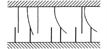
σ0z+σ1dzdt represents the friction generated from the curved bristles, while σ2v represents the viscous friction. The sum of both represents the contact surface friction:
where σ0 and σ1 represent the stiffness and damping of the bristles respectively; σ2 represents the viscous friction coefficient; and g, σ0, σ1, and σ2 usually determine the characteristic of the LuGre model. Thevalue of g is decided by the Stribeck effect:
where FS represents the Coulomb friction force; FC represents the static friction force; and vs represents the characteristic velocity of the Stribeck effect.
3.2. Design of backstepping integral controller
The mathematical model of the hydraulic servo system can be expressed by the following equations:
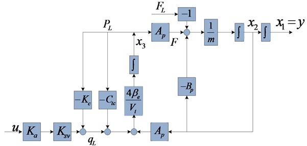
where qL – load flow; Kq – total flow coefficient of the servo valve; Kc – flow-pressure coefficient of the servo valve; pL – pressure drop of the load; Ctc – total leakage coefficient of the hydraulic cylinder piston; Vt – total compression volume of the cylinder; Ap – hydraulic cylinder piston effective area; βe – effective elastic modulus; F – driving force of the hydraulic cylinder piston; m – total mass of the piston and the rigid load; BP – damping coefficient of the hydraulic cylinder piston; FL – load force on the hydraulic cylinder piston; y – displacement of the piston.
Based on the theoretical mathematical model, when specific rigid specimens are tested, the parameters of the hydraulic system can be estimated, including the natural frequency and damping ratio. Subsequently, it can provide a theoretical basis for the design of the backstepping integral control strategy.
The three state variables, namely piston displacement x1(t), piston velocity x2(t), and load pressure drop x3(t) are defined by Eq. (5):
Without considering the dynamic characteristics of the servo valve and hydraulic cylinder leakage Ctc=0, KqXv=uKsvKa, where Ksv is the servo valve flow gain, Ka is the servo amplifier gain, and u is the driving voltage. The state equations are expressed as follows:
The output equation is expressed as:
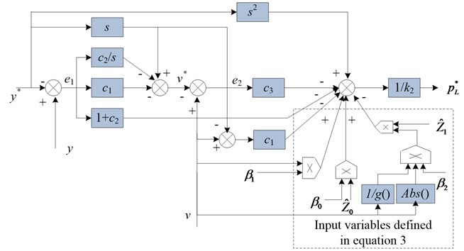
The block diagram of the system state variables is shown in Fig. 4, and the state equations can be simplified as follows:
where:
Fig. 4Block diagram of the system state variables
Because the average bristle deflection z of the LuGre model cannot be observed, dual observers are designed [23, 24] to obtain its value:
where, ι0 and ι1 represent the observer error compensation terms. By introducing the error compensation terms, we can reduce the bristle deflection difference between estimated values ˆz0, ˆz1 and actual observer values ˜z0, ˜z1. Its value is determined in the subsequent backstepping integral algorithm. By the following formula: ˜z0=z-ˆz0 and ˜z1=z-ˆz1, observer error equations are expressed as follows:
The formula indicates that the friction model contains the unobservable state variables and the traditional control algorithms, which are difficult to achieve. In this study, the backstepping integral control algorithm is applied to the hydraulic servo control system. It enables the system to approach the acceleration reference signal at a higher accuracy, while reducing the influence of the friction factors.
The system displacement tracking error signal is defined as e1:
where y* represents displacement reference signal.
The derivative form of the tracking error signal can be expressed as:
Using the backstepping integral control algorithm, the reference velocity signal α1 is designed as:
where χ1=t∫0e1(τ)dτ is the displacement error integral. In case of disturbance, the parameter can also enable the system tracking error to approach 0; The coefficients c1 and c2 are positive.
The speed error signal e2 is designed as the difference between the actual and reference velocity values:
The derivative form of Eq. (14) is expressed as:
According to Eqs. (13) and (14), (12) can be rewritten as follows:
Substituting the friction models, Eqs. (1) and (2) into Eq. (15) yields:
where β0=k3σ0, β1=k3(σ1+σ2)+k1, β2=k3σ1.
As σ0, σ1, and σ2 are unknown, β0, β1, and β2 are also unknown. In the following control algorithm design, these parameters will be identified and updated by adaptive methods.
The load pressure drop reference is designed as follows:
where c3 is positive. The e3 is the load pressure drop error signal, and the value is the difference between the load pressure and the reference pressure values:
Therefore, de2/dt can be rewritten as:
On the other hand:
The e2 of Eq. (18) is replaced by e2=v-α1 to obtain:
+(β1-c1-c3)v.
The load pressure drop error signal can be expressed as:
+1k2dϕ1dv[k2pL+β0z+β1v+|v|g(v)β2z],
where:
Using the backstepping integral control algorithm, the control law is designed as follows:
where is determined by the user.
Substituting into Eq. (21) yields:
From the Fig. 5, the control method has three closed-loops: the displacement, speed and pressure drop. As can be seen from the Eqs. (11)-(26), this control method can achieve the three closed-loop variables recurrence from inside to outside. Eventually, it can easily design the Lyapunov function. Under the premise of ensuring the stability of the system, the nonlinear system friction can be effectively compensated, and the desired system dynamics characteristic can be obtained.
The Lyapunov function is designed as follows:
Its derivative form is as follows:
The error compensation observers are selected as follows:
Then:
Selecting and , then:
According to the theory of stability, the servo test system is asymptotically stable, which proves that the method can ensure stability of the vibration test system in a limited time.
Fig. 5Scheme of backstepping integral control
4. Experimental results
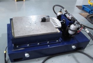
As shown in Fig. 6, the hydraulic shaking table is used to study the LuGre friction and verify the effectiveness of the backstepping integral control method.
The following are the parameters of the shaking simulation table: the rated sine force is 22.2 kN; maximum displacement is ±50 mm; maximum velocity is 0.6 m/s; maximum acceleration under fully loaded condition is 6 g; mass of shaker table is 100 kg; mass of the rigid load mounted on the shaker table is 100 kg; servo valve rated flow is 63 L; and rated drive current is ±40 mA.
The total mass of the piston and the rigid load m is 200 kg; effective elastic modulus is 7×10⁸ Pa; hydraulic cylinder piston effective area is 15.9×10⁻⁴ m2; total compression volume of the cylinder is 1.75×10⁻⁴ m3; total flow-pressure coefficient of the servo valve is 3.5×10⁻¹¹ m3/ Pa∙s; servo valve flow gain is 26.2×10⁻³ m3/s·A; servo valve amplifier gain is 4×10⁻³ A/V; and the driving voltage is ±10 V.
Fig. 6Shaking simulation test table
Then, the parameters of state equations are calculated: 0, 7.95×10⁻⁶ m2/kg, –5×10⁻³ kg-1, –2.54×10¹⁰ Pa/m, –5.6×10² s-1, 1.67×10⁹ pa/s·V,
The friction model parameters are set as follows: 6×10⁶ N·s/m, 6×10³ N·s/m, 10 N·m, 300 N, 500 N, 0.05 m/s, 400, 500, 300, 200.
To prove that the backstepping integral control method can improve the performance of the hydraulic servo system, the sine and earthquake experiments are carried out on the hydraulic shaking table. A comparative study is experimented between a PID control method without friction compensation and backstepping integral control method with friction compensation. The proportional (P) control can adjust the steady-state error and system response speed. The integral (I) control can eliminate the steady-state error of the system, but the big value assembly cause system instability. The differential (D) can predict error changing trends, thereby eliminating the system dynamic error. The PID parameters are artificially calibrated, the value is as follows: P = 2.5, I = 0.05, D = 0.1.
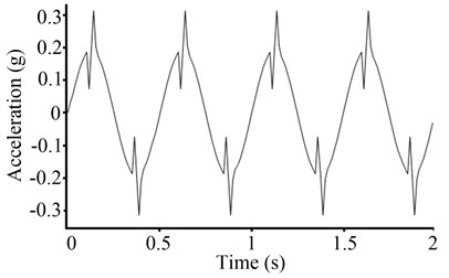
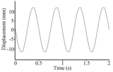
In this study, two different compensation methods are adopted. At a frequency of 2 Hz, sine testing at 0.2 g is experimented on the hydraulic shaking table. When the system reaches steady state, the acceleration control signal and the displacement control signal are recorded as shown in Fig. 7.
Fig. 7Waveforms of the PID control
a) Acceleration control signal
b) Displacement control signal
From Fig. 7, because of the shift from static to dynamic friction, the acceleration waveforms have an acceleration mutation at its peak, while the acceleration waveform distortion reaches 19 %, and peak acceleration relative error reaches 56 %. Displacement waveforms have a significant clipping at its peak, and displacement waveform distortion reaches 4 %. Thus, it is observed that friction can cause significant distortion on displacement waveforms and acceleration waveforms.
The same sine experiment is carried out under backstepping integral control method. First, it calculates the steady estimation error and of the friction state observers. As shown in Fig. 8, the steady state error estimation can be maintained in a small range value.
Furthermore, the use of control law generates drive signals, which are input to the system. The displacement control signal and acceleration control signal are shown in Fig. 9.
Fig. 8Estimation errors of the friction state observers
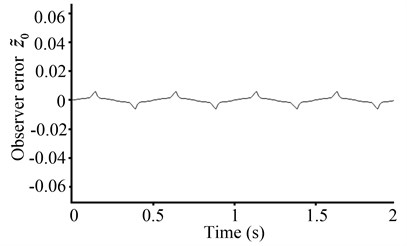
a) Estimation error
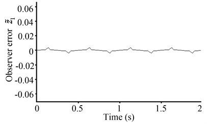
b) Estimation error
Fig. 9Waveforms of the backstepping integral control
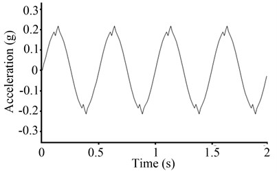
a) Acceleration control signal
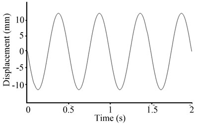
b) Displacement control signal
The sine experiment shows that compared to the PID control method without friction compensation, the backstepping integral control method can significantly decrease the disturbance caused by friction. The mutation of the acceleration waveform at its peak has been greatly reduced, while the acceleration waveform distortion and the peak relative error have also been reduced significantly. The acceleration waveform distortion is 5 %, and the peak relative error is 6 %. The clipping of displacement waveform is reduced significantly at its peak, and the displacement waveform distortion is reduced to 0.2 %.
To further verify the backstepping integral control method, the furthermore earthquake simulation experiment is carried out. Specific procedures are described as follows.
Step 1. This is the pretesting procedure used to obtain the initial reverse transfer function. The small magnitude white noise signal is taken as the drive signal input for the shaking test table. In the shaking test system, the initial reverse transfer function is estimated by the drive signal and the corresponding output signal.
To reduce the impact of noise on the system identification, the spectral analysis method is used to estimate the initial inverse transfer function of the system. The mathematical form is expressed as:
where is the inverse transfer function of the system, is the itself power spectrum of the drive signal, and is the mutual power spectrum between the drive signal and the output signal.
Step 2. Through the inverse fast Fourier transform (IFFT), the inverse transfer function is transformed into the time domain to obtain the inverse of the impulse response function.
Using the spectral analysis method, we can estimate the inverse transfer function, which contains the system amplitude and phase information. It can be directly transformed to the time domain by the IFFT. Then, we can obtain the inverse of the system impulse response function:
Step 3. The inverse of the system impulse response function and the reference signal are convoluted calculations, which produce the first frame driving signal. Then, it is input into the shaking table to formally begin the tests.
This step can be expressed as , where is the reference signal, is the driving signal, and is the inverse of the system impulse response function.
Step 4. The shaking table response signal at the first frame of the driving signal effect is measured, and the new driving and response signals are used to identify the inverse transfer function.
Step 5. Because earthquake simulation tests are generally multi-frame tests, the new identified inverse transfer function is transformed into the inverse of the system impulse response function, which is convoluted with a reference signal. Then, the second frame driving signal of the test system is obtained.
Step 6. The second and first frame driving signals are connected smoothly.
Step 7. The shaking response under the second frame driving signal is measured, and the new driving and response signals are used to identify the inverse transfer function.
Step 8. Steps 5 to 7 are repeated, and the third and second frame driving signals are connected smoothly. Then, the system inverse transfer function is updated again, until the end of the trial.
As can be observed, the control method can continue to estimate the transfer function of the system and update the driving signal. In the electro-hydraulic servo system of the earthquake simulation table, even if large changes of the transfer function appear, the control method can still achieve high control accuracy.
Consequently, the PID control method without friction compensation and backstepping integral control method with friction compensation are adopted to identify the system. The two reverse transfer functions of the system impedance are obtained, and the identification frequency is in the range of 0.25-20 Hz. As shown in Fig. 10 and Fig. 11, the two system impedance frequencies are more than 8 Hz. However, the system impedance identified without friction compensation has obvious glitches above the 8 Hz waveform. It shows that the system identification accuracy is relatively poor within that frequency range. The main reason is the nonlinear characteristic of the system friction. The friction causes the waveforms to generate mutations; hence, high-frequency components are abundant. Its energy content is mainly concentrated above 8 Hz. Using the backstepping integral control method with friction compensation, the waveform smoothness of the system impedance has improved greatly with a high identification accuracy.
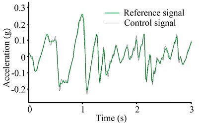
Iterative control algorithm is adopted in the earthquake simulation test, and the experiment reference wave is as follows: The El Centro earthquake wave, after filtering the reference signal frequency bandwidth, is in the range of 0.25-20 Hz; peak acceleration is 0.26 g; and peak displacement is 44 mm. With the above identified two system impedances, after five iterations, the earthquake simulation control time domain signals are shown in Fig. 12 and Fig. 13.
Compared with the acceleration reference signal, the acceleration control signals without friction compensation have an obvious distortion at the displacement commutation. For this reason, the system has a large difference of peak value between the acceleration control signal and the acceleration reference signal; the peak error is 14 %. Moreover, the friction worsens the correlation coefficient between the control signal and the reference signal in the time domain. The value of the coefficient is 88 %. After using the backstepping integral method, the peak error is reduced to 4.2 %, while the correlation coefficient is improved to 97 %.
Fig. 10System impedance of the PID control
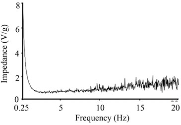
Fig. 11System impedance of the backstepping integral control
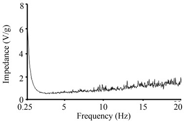
Fig. 12Shaking waveforms of the PID control
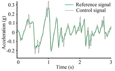
Fig. 13Shaking waveforms of the backstepping integral control
In the frequency domain, the earthquake analog waveform is analyzed after five iterations and are shown in Fig. 14 and Fig. 15.
Fig. 14System power spectral density of the backstepping integral control
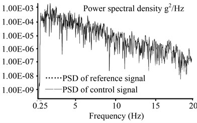
Fig. 15System power spectral density of the PID control
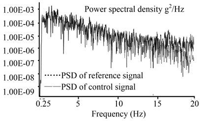
Compared to the acceleration reference signal power spectral density (PSD), the acceleration control signal PSD shows an error that mainly exists above 8 Hz. There are some high-frequency noise signals in the acceleration control signal. The noise frequency components are mainly distributed above 8 Hz, which is consistent with the system impedance function that has been analyzed in the above sections. After compensating for friction by adopting the backstepping integral method, the deviation peak of PSD is reduced from 2.9×10⁻⁵ g2/Hz to 1.3×10⁻⁶ g2/Hz.
5. Conclusions
In this study, the nonlinear friction of the hydraulic shaking table is analyzed. Based on the LuGre friction model, the shaking table test system friction compensation control is designed using the control theory of backstepping integral and the Lyapunov stability theory to ensure global asymptotic stability of the closed-loop system. The experiment carried out on the hydraulic shaking table verifies the effectiveness of the method. The conclusions are as follows.
1) Two nonlinear observers are designed to estimate online the unknown friction states of the LuGre friction model. The friction term and unknown interferences are inhibited by compensating the friction term, and the backstepping integral control algorithm is introduced to improve control performances. The procedure of iterative control algorithm is presented, and is used to estimate system impedance.
2) Compared to the PID control method, the proposed control method has achieved better system test accuracy both in the time domain and the frequency domain. The sine and earthquake experiments show that the proposed control method can effectively reduce the distortion of acceleration waveform, the peak error and peak deviation of PSD, while greatly improving the correlation coefficient between the control signal and the reference signal in the time domain.
References
-
Bialas K. Mechanical and electrical elements in reduction of vibrations. Journal of Vibroengineering, Vol. 52, Issue 1, 2012, p. 31-38.
-
Shen G., Zhu Z. C., Li X., et al. Real-time electro-hydraulic hybrid system for structural testing subjected to shaking and force loading. Mechatronics, Vol. 33, 2015, p. 49-70.
-
Tian P. Control Strategy Research on Replicate in Time Domain of Earthquake Simulation Shaker. Zhejiang University, 2015.
-
Shao X., Reinhorn A. M. Development of a controller platform for force-based real-time hybrid simulation. Journal of Earthquake Engineering, VVol. 16, Issue 2, 2012, p. 274-295.
-
Seki K., Iwasaki M., Kawafuku M., Hirai H., Yasuda K. Adaptive compensation for reaction force with frequency variation in shaking table systems. IEEE Transactions on Industrial Electronics, Vol. 56, Issue 10, 2009, p. 3864-3871.
-
Qian Y. L., Ou G., Maghareh A., Dyke S. J. Parametric identification of a servo-hydraulic actuator for real-time hybrid simulation. Mechanical Systems and Signal Processing, Vol. 48, Issue 1, 2014, p. 260-273.
-
Huang S. N., Tan K. K. Intelligent friction modeling and compensation using neural network approximations. IEEE Transactions on Industrial Electronics, Vol. 59, Issue 9, 2012, p. 3342-3349.
-
Zhou J., Zhang C. Y., Wen C. Y. Robust adaptive output control of uncertain nonlinear plants with unknown backlash nonlinearity. IEEE Transactions on Automatic Control, Vol. 52, Issue 3, 2007, p. 503-509.
-
Fang Y. M., Qi J., Li J. X., Xu Y. Z. Backstepping sliding mode control for continuous cast system driven by electro-hydraulic servo mold displacement system. Electric Machines and Control, Vol. 18, Issue 4, 2014, p. 96-102.
-
Xie W. F. Sliding-mode-observer-based adaptive control for servo actuator with friction. IEEE Transactions on Industrial Electronic, Vol. 54, Issue 3, 2007, p. 1517-1527.
-
Park S. H., Han S. I. Robust-tracking control for robot manipulator with dead zone and friction using backstepping and RFNN controller. LET Control Theory and Applications, Vol. 5, Issue 5, 2011, p. 397-1417.
-
Ma Y. L., Huang J., Zhang D. Backlash compensation in servo systems based on adaptive backstepping-control. Control Theory and Applications, Vol. 25, Issue 6, 2008, p. 1090-1095.
-
Xiang H. B., Tan W. B., Li X. F., Zhang C. Y. Adaptive friction compensation based on LuGre model. Journal of Mechanical Engineering, Vol. 48, Issue 17, 2012, p. 70-74.
-
Milic V., Situm Z., Essert M. Robust H∞ position control synthesis of an electro-hydraulic servo system. ISA Transactions, Vol. 49, Issue 4, 2010, p. 535-542.
-
Shen G., Zhu Z. C., Zhang L., et al. Adaptive feed-forward compensation for hybrid control with acceleration time waveform replication on electro-hydraulic table. Control Engineering Practice, Vol. 21, Issue 8, 2013, p. 1128-1144.
-
Han S., Lee K. Robust friction state observer and recurrent fuzzy neural network design for dynamic friction compensation with backstepping control. Mechatronics, Vol. 20, Issue 3, 2010, p. 384-401.
-
De Wit, Canudas C., et al. A new model for control of systems with friction. IEEE Transactions on Automatic Control, Vol. 40, Issue 3, 1995, p. 419-425.
-
Farid A. B., Vincent L., Jan S. The generalized Maxwell-slip model: a novel model for friction simulation and compensation. IEEE Transactions on Automatic Control, Vol. 50, Issue 11, 2005, p. 1883-1887.
-
Wu Y. F., Ma D. W., Yao J. Y., Le G. G. Application of adaptive robust control in mechatronic servo system based on modified LuGre model. Journal of Mechanical Engineering, Vol. 50, Issue 22, 2014, p. 207-212.
-
Lu L., Bin Y., Qing F. W. Adaptive robust control of linear motors with dynamic friction compensation using modified LuGre model. Automatica, Vol. 45, Issue 12, 2009, p. 2890-2896.
-
Yao J., Deng W., Jiao Z. Adaptive control of hydraulic actuators with LuGre model-based friction compensation. IEEE Transactions on Industrial Electronics, Vol. 62, Issue 10, 2015.
-
Xie H., Liu Z., Yang H. Advancing control for shield tunneling machine by backstepping design with LuGre friction model. Mathematical Problems in Engineering, Vol. 11, Issue 5, 2014, p. 809-812.
-
Morawiec M. The adaptive backstepping control of permanent magnet synchronous motor supplied by current source inverter. IEEE Transactions on Industry Information, Vol. 9, Issue 9, 2013, p. 1047-1055.
-
Della L. F., Gründling H. A. Time domain sinusoidal acceleration controller for an electrodynamic shaker. IET Control Theory and Application, Vol. 2, Issue 12, 2008, p. 1044-1053.
About this article
The authors declare that there is no conflict of interests regarding the publication of this paper.

