Abstract
The paper presents a shock absorber whose working element includes two magnetic fluid rings around a group of magnets. The damping efficiency of this shock absorber is investigated by the free oscillations of an elastic plate and can be well explained with the classical equations of motion. In the shock absorber, a nonlinear equivalent stiffness is provided by the magnetic repulsion force, which controls the movement of the working element and varies in conformity to a power law. Through the theoretical and experimental study on the magnetic repulsion force, the nonlinear equivalent stiffness is determined and depends on the initial distance between the working element and the repulsion magnet. For an oscillation with the amplitude of 1mm and frequency of 1.1 Hz, the damping efficiency is inversely proportional to the nonlinear equivalent stiffness.
1. Introduction
Magnetic fluid, also called ferrofluid, is a kind of colloidal liquid made of nanoscale ferromagnetic, or ferrimagnetic, particles suspended in a carrier fluid, typically water, oil or ester, which has lots of outstanding magnetic and rheological properties in response to impressed magnetic field [1, 2]. A number of engineering applications of magnetic fluid have been found since it was available in the mid-1960s [3-5]. Eliminating the vibration was one of the most prospective applications of magnetic fluid [6]. Like the magnetorheological (MR) fluid, an earlier liquid magnetic material with the micrometre-scale particles, the magnetic fluid is also expected as a controllable damping material in the presence of an external magnetic field. Hence there are some attempts in using the magnetic fluid to develop the vibration isolator [7, 8]. However, the apparent viscosity of the magnetic fluid increases slightly with the increase of the external magnetic field. And no matter how strong magnetic field is, its yield stress is almost negligible. Therefore, the control range of the damping in these devices will be limited compared with that using magnetorheological (MR) fluid.
Everything has two sides. A small apparent viscosity in strong magnetic field means an extremely great fluidity. Such a relatively ‘softer’ magnetic fluid shows its advantages in various dampers [9-12]. The magnetic fluid is inserted in the space between moving parts and stationary parts, being retained by strong magnetic forces. The magnetic field can be generated by the permanent magnet or electromagnet. The magnetic fluid may fill or partially fill the damper space. Relative motion between the two parts is damped by a shear force resulting from the flow of the magnetic fluid, which reduces the oscillation and extension of the moving parts. In recent years, the viscous properties of magnetic fluid are also used in the tuned liquid damper (TLD) to enhance the performance of the TLD [13, 14]. The TLD with a magnetic fluid as the working fluid is called a tuned magnetic fluid damper (TMFD). The TMFD has a characteristic that the natural sloshing frequency can be changed by the external magnetic field.
But more interestingly, in order to eliminate the local oscillation of the solar panels and antennae, several shock absorbers using the unusual self-levitation of an immersed magnet are proposed in [15-18]. The unique buoyancy phenomenon is defined as the second kind levitation principle of ferrofluid in [19, 20]. Unlike a piezoelectric material, without the external power supply (zero energy waste) is one of the most important advantages for these devices.
In particular, a magnetic fluid shock absorber is presented in [15], which exploits a magnetic fluid drop with a self-levitating permanent magnet as a dissipating element when the external oscillations are applied. Its excellent performance with small amplitude (less than 1mm) and small frequency (less than 1 Hz) is best for removing the vibration problems in spacecraft technologies.
Another innovative magnetic fluid shock absorber is presented in [16, 17]. Actually, the device exploits a magnet free-to-move inside a nonmagnetic body filled with magnetic fluid. A non-linear repulsion force resulting from the compression of the magnetic fluid will bounce the magnet back. However, the joint action of the Couette and Poiseuille flow will lead to a large damping coefficient. So, it is difficult to remove the oscillation with small amplitude (less than 3 mm). If the device only needs a small amount of magnetic fluid, it will be a Lanchester-like passive damper.
A Lanchester-like passive damper shows a good experimental result in [18]. The limit of the flow has been addressed, but the repulsion force disappears. For reducing low-amplitude oscillations, an electromagnet is located at the extremity of the tube. The idea to use the magnetic repulsion force as a secondary mass in shock absorber offers an opportunity to change the stiffness, which means an active damper instead of a passive one. However, it is inevitable for the consumption of the electric energy provided by the solar panels.
In this paper, a magnetic fluid shock absorber based on the self-levitating permanent magnets is presented. Two magnetic fluid rings can not only provide the working element a light mobility due to liquid fluidity, but also work as a kind of viscous damping materials. During the oscillation, the equilibrium location of the working element is maintained by a magnetic repulsion force, which results from two repulsion magnets fixed at the ends of the cylindrical body. Such a shock absorber can operate with a nonlinear stiffness varying in conformity to a power law. It means that the larger amplitude is applied to the device, the larger stiffness will increase. Therefore, this design can prevent the working element from hitting the body. The damping efficiency of this shock absorber will be discussed in the following sections.
2. Structure design
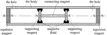
The magnetic fluid shock absorber is presented in Fig. 1. It includes a cylindrical body made of non-magnetic material, a working element and two repulsion magnets. The working element consists of two magnetic fluid rings and a group of magnets, which can suspend steadily in the body due to the compression of the magnetic fluid. So, the working element is the most sensitive to the influence of external oscillations due to liquid fluidity. Two repulsion magnets are fixed at the ends of the cylindrical body, which provides a magnetic repulsion force to maintain the axial position of working element in the body. Changing the strength of the forces allows modifying the performance and working range of the shock absorber.
Fig. 1a) Scheme of the magnetic fluid shock absorber and b) the working element
a)

b)
When the working element moves from the initial position under the influence of external oscillations, the flow of magnetic fluid will occur in the gap between the supporting magnets and the body. The damping depends on the physical characteristic of the magnetic fluid, magnets, body and their geometry. To exclude the influence of compressing air, two holes are opened at the ends of the body near the two repulsion magnets, respectively. The same design can be found in [18].
In preliminary tests of an experimental model, the performance parameter of the shock absorber is tested by the free oscillations of an elastic plate with one end fixed and the other free as shown in Fig. 2. For the damping system with two degrees of freedom in free vibration, the equations of motion are:
where is the equivalent mass of the body, magnetic fluid and elastic plate, is the mass of working element, and are the displacements of the elastic plate and working element, respectively, and are the equivalent damping and the equivalent stiffness of the elastic plate, respectively, is the fluid resistance and is the magnetic repulsion force.
Fig. 2Scheme of the elastic plate
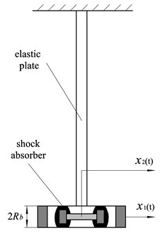
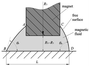
Fig. 3A mechanical model for analysis of the flow of the magnetic fluid
3. Theory analysis
3.1. Calculation of the fluid resistance
The mechanical model of the magnetic fluid in the gap between the body and the supporting magnets is shown in Fig. 3. The lines and represent the magnetic fluid film.
When the body oscillates, the fluid resistance acting on the working element results from the joint action of the capillary force and the hydrodynamic drag force.
For small ratio , the hydrodynamic drag force between the body and the fluid can be estimated approximately:
where is the external surface, is the inner diameter of the body. The viscosity is only a function of magnetic field under the condition of a small oscillating frequency.
The viscosity for a planar Couette flow under the magnetic field can be given by [21]:
where , is the volume fraction of the magnetic fluid, is the viscosity of the magnetic fluid in the absence of a magnetic field, is the angle between magnetic field and vorticity. For a large magnetic field and the magnetic field perpendicular to the vorticity , the viscosity is found:
The pressure and temperature can be assumed to be constants in case of a small amplitude and Reynolds numbers. The no-slip condition will set the fluid into steady motion , while and will be zero. According to Navier-Stokes equation, the axial momentum equation reduces to:
So, the velocity profile has the form:
with the boundary conditions 0 and ( is the relative velocity between the magnets and the body), the solution is:
Using Eqs. (2), (4) and (7), the hydrodynamic drag force finally writes:
where and are the diameter and height of the supporting magnet, respectively.
The capillary force acting against the motion is:
where is the surface tension of the magnetic fluid, and are the advancing and receding contact angles. is the contact length between the magnetic fluid and the body, which depends on the volume of magnetic fluid. Compared with the magnitude of the hydrodynamic drag force, the capillary force is so small that it can be reasonably neglected. So, the fluid resistance can be rewritten:
3.2. Calculation of the magnetic repulsion force
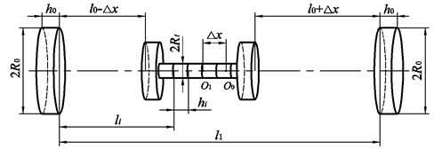
Fig. 4. shows the model of the magnetic repulsion force.
When the working element moves away from the center point to the point , the force equilibrium relationship will be broken. So can be written:
where and are the force and distance between the left repulsion magnet and the magnet with No. , respectively, is the number of a combination of magnets and is the distance between two repulsion magnets. The solution of the force is introduced in [22]. The force may be written:
where , is the magnetization of magnets, and are the radii and heights of the repulsion magnets, respectively, and are the radii and heights of the combination of magnets, respectively, is a modified Bessel function of the first kind. A simpler equation for distances larger than the diameter of magnets is described by the expression:
Fig. 4A scheme of the magnetic repulsion force between the working element and repulsion magnets
4. Experiment
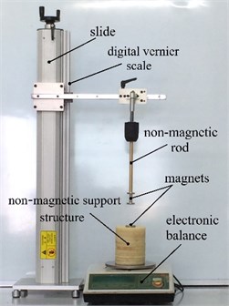
Fig. 5 shows the experimental apparatus which is used to measure the magnetic repulsion force between the working element and a single repulsion magnet. The upper end face of the working element is fixed at a non-magnetic rod, which can move along a slide. A digital Vernier scale with an accuracy of 0.01 mm installed on the slide can be used to measure the displacement of the working element. The repulsion magnet is fixed at an electronic balance with an accuracy of 0.01 g. In order to avoid the influence of these magnets on the electronic balance, there is a nonmagnetic support structure with the height of 15 cm between the repulsion magnet and electronic balance. The experimental steps are given as follow:
The first step, install the working element, nonmagnetic rod and the nonmagnetic support structure, respectively. The second step, adjust the height of the working element to find the position at which the reading of the electronic balance begins to change. This position means where the working element and the nonmagnetic support structure are in contact. Then move up the working element with a displacement as the zero position and clear the reading of the digital vernier scale. The third step, move the working element far away from the nonmagnetic support structure and fix the repulsion magnet at the nonmagnetic support structure. Finally, clear the reading of the electronic balance and move the working element with a step of 0.62 mm, the reading changes and the relationship of the magnetic restoring force versus the distance can be obtained.
Fig. 5Experimental apparatus to measure the magnetic repulsion force
The elastic brass plate with dimensions 1200 mm×50 mm×5 mm is fixed on one end and the other free end is installed with the magnetic fluid shock absorber. The amplitude and frequency of free oscillations of the plate are equal to 1 mm and 1.1 Hz, respectively. The main parameters of the magnets are shown in Table 1. The body has an inner diameter 30 mm. The equivalent damping and equivalent stiffness of the elastic plate are 3.52×10⁻² kg/s and 118.33 N/m, respectively. The equivalent mass of the body and elastic plate is 1.93 kg and the mass of working element is 47.7 g. The laser displacement sensor HL-G108-A-C5 has a resolution of 2.5 μm ensuring the accuracy of experiment. A data acquisition instrument (DI-710) with a sampling frequency of 50 Hz collects the electrical signal. The ester-based magnetic fluid is produced by our laboratory and has a saturation magnetization of 208 Gs, viscosity of 0.27 Pas and density of 1.07 g/cm³.
Table 1Used parameters of the magnets
Description | Dimensional parameter | Value |
Diameter of the repulsion magnet | 30 mm | |
Height of the repulsion magnet | 5 mm | |
Diameter of the supporting magnet | 25 mm | |
Height of the supporting magnet | 5 mm | |
Diameter of the connecting magnet | 10 mm | |
Height of the connecting magnet | 2.5 mm | |
The number of the connecting magnet | 12 | |
Magnetization of all magnets | 0.89 MA/m |
5. Results and discussion
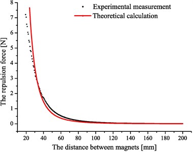
Fig. 6 shows two curves of the magnetic repulsion force between a single repulsion magnet and the working element by experimental measurement and theoretical calculation based on Eq. (13), respectively.
In Fig. 6, the small discrepancy between measured and calculated may result from the approximate theoretical analysis. When the displacement is small enough, the magnetic repulsion force will be assumed to be linear. Now, Eq. (11) can be rewritten:
where is the equivalent stiffness. In order to investigate the influence of the equivalent stiffness on the damping efficiency of the shock absorber, we prepare the body of the shock absorber with nine different lengths (185 mm, 193 mm, 198 mm, 205 mm, 209 mm, 217 mm, 221 mm, 230 mm and 238 mm), which correspond to nine different initial distances (75 mm, 79 mm, 81.5 mm, 85 mm, 87 mm, 91 mm, 93 mm, 97.5 mm and 101.5 mm), respectively.
Fig. 6Diagram of the magnetic repulsion force versus the distance
For a free oscillation with one degree of freedom, the logarithmic decay rate is expressed as:
where is the amplitude of the first oscillation and is the amplitude of the th oscillation. In order to evaluate the damping efficiency of the oscillation system with two degrees of freedom under a dimensionless form, the logarithmic decay rate will be calculated preliminarily by Eq. (15) based on the condition of .
Fig. 7. shows the dependence of the logarithmic decay rate on the initial distance between the repulsion magnet and the supporting magnet. These data are obtained when the volume of magnetic fluid is 9.12 ml. At this time, the contact length can be measured with a value of 18 mm, and the equivalent stiffness for various initial distances can be obtained in Fig. 8. The results demonstrate a good agreement between the experiment and theory.
Fig. 7Diagram of the dependence of the logarithmic decay rate on the various initial distances l0
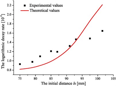
Fig. 8Diagram of the dependence of the equivalent stiffness Keq on the various initial distances l0
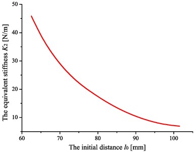
The results indicate that the logarithmic decay rate increases with the increase of the initial distance , which will induce the decrease of the equivalent stiffness in Fig. 8, and then the movement of the working element will be easier. When the equivalent stiffness is small enough, the magnetic fluid shock absorber will turn into a Lanchester-like damper and the energy dissipation will reach the greatest effect. However, the device is not suitable to be used in the spacecraft technology without the repulsion force trying to return the working element to its initial position.
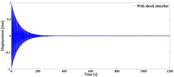
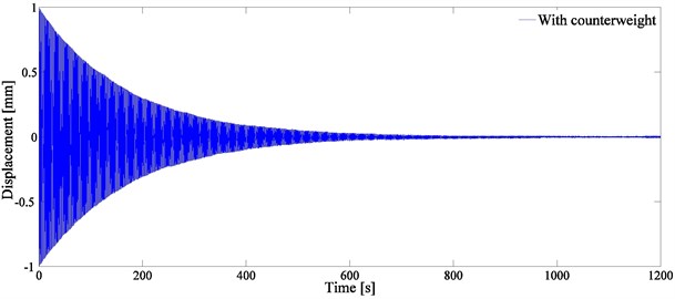
In Fig. 7, the shock absorber with the initial distance 101.5 mm has the maximum logarithmic decay rate. In order to further investigate the vibration behavior of the system, a comparative experiment through installing a counterweight at the plate has been performed. The mass of the counterweight is equivalent to that of the shock absorber. Fig. 9 shows the plate oscillations with the shock absorber and with the counterweight.
Fig. 9Diagram of the plate oscillations a) with the shock absorber and b) with the counterweight
a)
b)
6. Conclusions
In this paper, a magnetic fluid shock absorber is presented and the corresponding theoretical models are built. In this shock absorber, a nonlinear equivalent stiffness is provided by means of the magnetic repulsion force. In order to investigate the nonlinear equivalent stiffness, we calculated and measured the magnetic repulsion force, which varies in conformity to a power law. With increasing the initial distance between the working element and the repulsion magnet, this shock absorber can obtain a smaller stiffness. Through measuring the free oscillations of an elastic plate, the damping efficiency of the shock absorber is inversely proportional to the nonlinear equivalent stiffness. According to the comparison between the theoretical and the experimental values, the theoretical models are suitable. Moreover, the shock absorber has a significant energy dissipation for the amplitude of 1mm and frequency of 1.1 Hz. The device might be used in spacecraft technology with the advantages of low cost, simple structure, and zero energy waste.
References
-
Rinaldi C., Chaves A., Elborai S., He X., Zahnb M. Magnetic fluid rheology and flows. Current Opinion in Colloid and Interface Science, Vol. 10, Issue 3, 2005, p. 141-157.
-
Kamiyama S., Koike K. Hydrodynamics of magnetic fluids. Brazilian Journal of Physics, Vol. 25, Issue 2, 1995, p. 83-100.
-
Raj K., Moskowitz R. Commercial application of ferrofluids. Journal of Magnetism and Magnetic Materials, Vol. 85, Issue 1, 1990, p. 233-245.
-
Raj K., Moskowitz B., Casciari R. Advances in ferrofluid technology. Journal of Magnetism and Magnetic Materials, Vol. 149, Issue 1, 1995, p. 174-180.
-
Scherer C., Figueiredo Neto A. M. Ferrofluids: properties and applications. Brazilian Journal of Physics, Vol. 35, Issue 3, 2005, p. 718-727.Raj K., Moskowitz R. A review of damping applications of ferrofluids. IEEE Transactions on Magnetics, Vol. 16, Issue 2, 1980, p. 358-363.
-
Fukuda H., Ueno K., Kamiyama S., Oyama T. Study on active damper with a magnetic fluid. JSME International Journal Series B Fluids and Thermal Engineering, Vol. 41, Issue 4, 1998, p. 822-829.
-
Jun L. Analysis of a porous elastic sheet damper with a magnetic fluid. Journal of Tribology, Vol. 131, Issue 2, 2009, p. 1-5.
-
Missiles A. Feasibility Study and Model Development for a Ferrofluid Viscous Damper Final Report. Space and Electronics Group, Report No. NASA-CR-94173, AVSSD-0222-67-CR, 1967, p. 234.
-
Leo B., Rudolph L. Viscous Damper Using Magnetic Ferrofluid. U.S. Patent 3,538,469, 1970.
-
Miller D. L. Magnetic Viscous Damper. U.S. Patent 4,200,003, 1980.
-
Buzduga C. Ferrofluids and Their Uses in Industry. The third International Symposium on Electrical Engineering and Energy Converters, 2009, p. 24-25.
-
Ohira Y., Houda H., Sawada T. Effect of magnetic field on a tuned liquid damper using a magnetic fluid. International Journal of Applied Electromagnetics and Mechanics, Vol. 13, Issues 1-4, 2001, p. 71-78.
-
Ohno K., Sawada T. An effect of vertical sloshing on a fluid pressure and a surface displacement in a tuned magnetic fluid damper. International Journal of Applied Electromagnetics and Mechanics, Vol. 33, Issues 3-4, 2010, p. 1411-1416.
-
Bashtovoia V. G., Kabachnikova D. N., Kolobovb A. Y., Samoylova V. B., Vikoulenkov A. V. Research of the dynamics of magnetic fluid dynamic absorber. Journal of Magnetism and Magnetic Materials, Vol. 252, 2002, p. 312-314.
-
Yang W., Li D., Feng Z. Hydrodynamics and energy dissipation in a ferrofluid damper. Journal of Vibration and Control, Vol. 19, Issue 2, 2013, p. 183-190.
-
Yao J., Chang J., Li D., Yang X. The dynamics analysis of a ferrofluid shock absorber. Journal of Magnetism and Magnetic Materials, Vol. 402, 2016, p. 28-33.
-
Wang Z., Bossis G., Volkova O., Bashtovoi V., Krakov M. Active control of rod vibrations using magnetic fluids. Journal of Intelligent Material Systems and Structures, Vol. 14, Issue 2, 2003, p. 93-97.
-
Rosensweig R. E. Buoyancy and stable levitation of a magnetic body immersed in a magnetizable fluid. Nature, Vol. 210, 1966, p. 613-614.
-
Rosensweig R. E. Fluidmagnetic buoyancy. AIAA Journal, Vol. 4, Issue 10, 1966, p. 1751-1758.
-
Shliomis M. I. Effective viscosity of magnetic suspensions. Journal of Experimental and Theoretical Physics, Vol. 61, 1971, p. 2411-2418.
-
Vokouna D., Beleggiab M., Hellera L., Šittnera P. Magnetostatic interactions and forces between cylindrical permanent magnets. Journal of Magnetism and Magnetic Materials, Vol. 321, Issue 22, 2009, p. 3758-3763.
About this article
This work was supported by the Fundamental Research Funds for the Central Universities (Grant No. 2016YJS135).
