Abstract
The ability to perform vertical takeoff and landing reliably and safely is of great concern for a near space travel lander carrying passengers. Oblique and uneven terrains can severely limit the degree of landing safety, so mission adaptive landing gear is designed and analyzed for its function of automatic adjustment before touchdown. The legs of mission adaptive landing gear are composed of shock absorbers and actuating cylinders, which can adjust angles of the main struts relative to the capsule under control, ensuring all feet touch the irregular surface together. Compared with a conventional landing gear, scaled test and dynamic simulation in three typical conditions verify that the new design can reduce the rotation angle and the translational motion of the capsule to less than 3 degrees and 1 meter, respectively. For buffer process, the overall design reduces peak load of the lander by more than 24 %, enhances efficiency of the shock absorber to more than 85 % and optimizes stroke lengths of shock absorbers. While landing on a slope with an angle of less than 31 degrees, mission adaptive landing gear can ensure the capsule’s maximum overload less than 5 and the capsule’s attitude angle less than 20 degrees, respectively. Landing performance shows that mission adaptive landing gear is robust to uncertain conditions of the landing surface.
1. Introduction
“Near space” generally refers to 20 km to 100 km airspace from the ground, and it is a new airspace that does not belong to the traditional category of the aerospace nor the space of aviation [1]. Near space travel vehicle lift by a helium balloon is rapidly developing [2], because it can arrive in complex areas such as the stratosphere unreachable by some fixed-wing aircraft. A flight profile of the high-altitude balloon made by New Mexico Institute of Mining and Technology [3] includes 57 minutes of float at 31 km and approximately 30 minutes of decent. A balloon equipped with an instrumentation package is designed by Millikin University [4] to travel into the near-space region of the atmosphere, and it lands successfully so that the team can analyze the data from the flights. For safe landing and takeoff of near space travel vehicle carrying passengers, design and analysis of the landing gear are of great concern.
Since it is first developed, the landing gear of vertical takeoff and landing (VTOL) aircraft has proven to be an invaluable tool for landing in remote areas, so its application becomes more and more extensive [5]. There are some successful examples, for instance, VTOL rocket’s landing gear [6], the helicopter’s landing gear [7] and lunar lander [8] etc. The lander containing payload is in danger of bouncing and tipping over when it lands on an oblique terrain. It is necessary to design a landing gear with a function of automatic adjustment adaptive to different landing surfaces.
To achieve slope landing requirements, several adjusting approaches are developed. An adaptive landing gear for helicopter is freely movable toward a retracted position and can be locked in any position of retraction, so as to permit the fuselage and rotor of the helicopter to maintain horizontal [9]. An adaptive landing gear capable of active adaptation to particular landing conditions by means of controlled hydraulic force is developed by Institute of Fundamental Technological Research [10]. The simulation of reusable rocket Falcon 9 with landing on a barge of the first stage has been assessed by German Aerospace Center [11], but the retractable landing gear cannot adjust during touchdown. A legged robotic gear system is designed by Georgia Institute of Technology for rotorcraft [12]: If a leg ever contacts the ground, the joint damping values are set to zero and the joints on the corresponding leg freely compress as the aircraft descends, and then the joints behave elastically after all feet are in contact [13]. The development of the articulated landing gear may enhance the usability of this kind of VTOL aircraft, but its adjustment and touchdown happen at the same time, so the impact loads can do harm to joint damping.
Mission adaptive landing gear (MALG) is built for a near space travel capsule. The new design employs infrared distance sensors located on skid plates to properly sense the vertical height of each foot. On the basis of the measured data, actuating cylinders on each leg work and adjust the angles of main struts relative to the capsule, ensuring that four skid plates touch the oblique terrain at the same time. As a result, the payload maintains horizontal during the whole process of slope landing. The mathematical model of the new design is established based on the dynamic simulation software ADAMS. Dynamic simulation and scaled test are performed to properly show the optimized results of MALG including peak overload, landing attitude, buffering property and limit slope angle.
2. Virtual prototype design
2.1. Virtual prototype of the lander
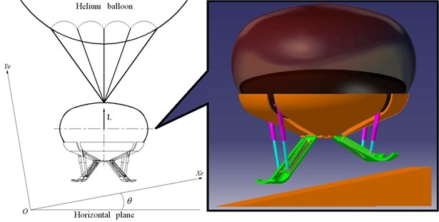
The lander simulated is chosen to be a reusable near space travel capsule equipped with MALG replacing the conventional landing gear. The lander has a mass of 2500 kg, as the capsule has a mass of 2250 kg and the landing gear has a mass of 250 kg. The lander is lift by a helium balloon, whose lift force equals to 4/5 of the gravity of the lander at the moment of touchdown, so the composition of forces of the lander is equivalent to 1/5 of the gravity of the lander in the Earth’s gravity [14]. The lander can only perform vertical landing, because it lacks airplane wheels which can handle horizontal motion. The vehicle lands at a vertical speed of 5 m/s on the soil terrain which can provide soil spring force and attenuate the stroke. A detailed schematic is shown in Fig. 1.
Fig. 1Virtual prototype of the lander
2.2. Virtual prototype of MALG
It is necessary to guarantee the security and stability of the vehicle. A ‘four legs-cantilever beam’ is adopted as the landing gear configuration. To tackle incline terrains of various sizes, each leg of MALG is composed of an infrared distance sensor, a skid plate, an actuating cylinder, a shock absorber and a main strut. A detailed schematic is shown in Fig. 2.
Fig. 2MALG configuration (dimensions in millimeters)
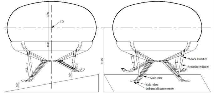
Before touchdown, the infrared distance sensor emits infrared radiation beneath the skid plate to determine how far away the oblique terrain is. The return analog voltages are used to determine the vertical distance between the skid plate and the nearest ground directly beneath the foot. Based on the return data above, the controller outputs the adjusting lengths and instructs the actuating cylinder to adjust. The actuating cylinder uses a brushless motor to actuate the nut screw mandrel to move along the axis of the shock absorber, in order to become shorter or longer under control. The angles of the main struts relative to the capsule change with the lengths of the actuating cylinder, so that the vertical distances from four skid plates to the irregular landing surface can be changed to the same value.
To absorb the kinetic and potential energy without causing the lander to be toppled, each leg of MALG has an oleo-pneumatic shock absorber with single-cavity and single-damping, which is adopted for its great power absorption and high buffering property. The sectional area of the oil pin in the shock absorber changes with stroke length adaptive to different impact conditions. A detailed schematic is shown in Fig. 3.
Fig. 3Shock absorber and actuating cylinder schematic

2.3. Slope landing controller
Based on measured vertical distances from the ground directly beneath the feet to the skid plates, a controller is used to analyze the data and control the adjustment of the actuating cylinders. The aim of the adjustment is to ensure four feet touch the oblique terrain at the same time, so the capsule can keep nearly horizontal during landing.
If the measured vertical distance in an infrared distance sensor is less than 5 m, the lift force of the helium balloon increases in order to keep the lander suspended. Then the leg whose measured distance is second long is fixed, and the vertical distances from the other three adjusted legs are compared with the fixed leg. The control system calculates deviations of the vertical distances in order to output the adjusting lengths of the actuating cylinders. After that the brushless motors work and actuate the nut screw mandrel to relatively move along their axes, in order to change the lengths of actuating cylinder. The heights of skid plates change with the angles of main struts until all deviations of measured vertical distances decrease to 5 mm. At last the lander drops from 6.25 m high approximately, whose vertical acceleration is equivalent to 1/5 of gravitational acceleration, so the vehicle lands at a vertical speed of 5 m/s approximately. The skid plates of the lander touch the oblique terrain and the shock absorbers start to take actions. Slope landing controller decision tree is shown in Fig. 4.
Fig. 4Slope landing controller decision tree

2.4. Scaled model test
A scaled model of the lander is manufactured for drop tests, in order to measure and analyze the capsule’s attitude angle after touchdown. By using the technique of dynamic scaling [14], the model has the desirable characteristics of being untethered, of having a convenient size and weight for handling, and of having easily obtainable mass properties. A comparison of the time histories of center-of-gravity accelerations obtained during full-scale and scaled model landing, the time histories are generally in good agreement [15].
According to dynamics similarity laws of the lander [15], the resulting model is constructed to a 1/5-dimensional scale and a (1/5)3-mass scale. The ratio of the scaled model touchdown velocities to the touchdown velocities of the full-scale model is 1. A 1/5 scaled model of the lander and a 1/5 scaled MALG are used, and the mass of the whole vehicle is 20 kg. The source of the lift force is chosen to be an unmanned aerial vehicle with eight rotors replacing the helium balloon, as the direction of the lift force can be controlled. According to dynamics similarity laws of the lander [15], the scaled vehicle drops with gravitational acceleration after MALG’s adjustment is done, and it lands at a vertical speed of 5 m/s. So, the drop height of the vehicle in scaled test is 1.27 m.
Fig. 5Virtual prototype of scaled model

According to the slope landing controller decision tree in Fig. 4, the vertical distances measured in infrared distance sensors of adjusted legs are compared with the data from the fixed leg, in order to output the adjusting lengths of the adjusted legs. So, the controller is also suitable for the ‘three legs’ or ‘five legs’ lander. In 1/5 scaled test, the horizontal distances of skid plates are too small to distinguish vertical distances of different skid plates from uneven terrain, so a ‘three legs-cantilever beam’ configuration is used to improve the accuracy of vertical distance data, because the horizontal distances of skid plates are expanded. Scaled model and drop test are shown in Figs. 5-6, respectively.
Fig. 6Snapshots of scaled drop test
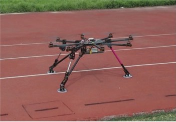
a) Launch
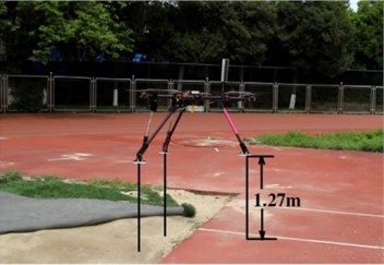
b) Adjusting done
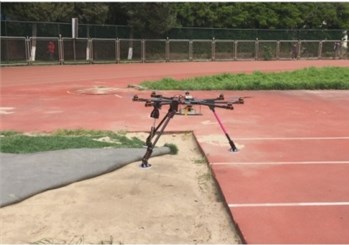
c) Land
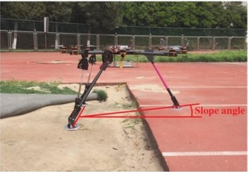
d) Touchdown
In scaled drop test, the vehicle lands on different slope terrains as MALG takes action or not, and rotation angles of the capsule are measured after touchdown which are shown in Table 1.
Table 1Scaled test results
Surface slope angle (degree) | Measured touchdown speed (m/s) | Landing result MALG used | Fuselage rotation angle (degree) MALG used | Landing result MALG not used | Fuselage rotation angle (degree) MALG not used |
5 | 4.7 | Success | 2.4 | Success | 6.2 |
10 | 4.9 | Success | 2.5 | Success | 9.7 |
15 | 4.8 | Success | 3.1 | Success | 16.0 |
20 | 4.6 | Success | 8.5 | Failure | Tip over |
25 | 4.7 | Success | 11.7 | Failure | Tip over |
30 | 5.3 | Success | 13.6 | Failure | Tip over |
35 | 4.9 | Success | 19.6 | Failure | Tip over |
40 | 5.1 | Failure | Tip over | Failure | Tip over |
45 | 5.1 | Failure | Tip over | Failure | Tip over |
The scaled vehicle with MALG tips over when the slope angle is increased to 40 degrees. The scaled vehicle with conventional landing gear tips over when the slope angle is increased to 20 degrees. MALG adopted keeps the capsule nearly horizontal after landing on 15 degrees slope. According to the comparison of fuselage rotation angles in Table 1, using MALG can enhance the adaptive ability to slope landing surface.
3. Mathematical model
3.1. Landing dynamic model
Virtual prototyping technology is used for simulating the drop process of the lander. Landing modes including 1-2-1 mode (one leg touches the surface first, and then two legs touch the surface simultaneously, the forth leg touches the surface at last) and 2-2 mode (two legs touch the surface simultaneously first, the other two legs touch the surface at last) [16] are investigated in this thesis. A lander’s two-dimensional mathematical model (using 1-2-1 mode) is established and shown in Fig. 7.
Fig. 7Two-dimensional lander configuration
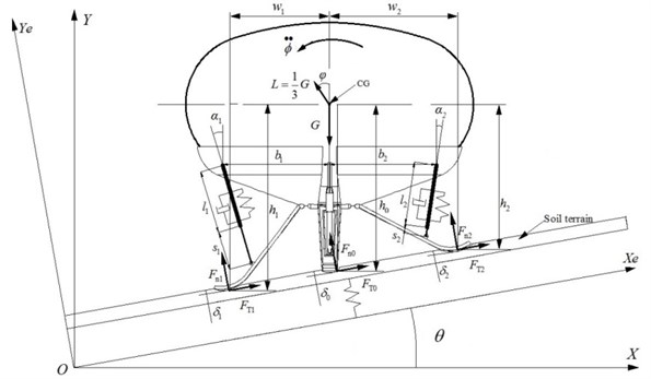
Dynamic differential equations in inertial coordinate system - are developed and denoted as:
where , and are the acceleration value of elastic support mass along - direction, the acceleration value of - direction and the angular acceleration under inertial coordinate system, respectively; is the vehicle’s altitude angle; is the angle between the landing surface and the horizontal; is the weight of the lander; is the lift force of the helium balloon; , and are the length of the shock absorber, the length of the actuating cylinder and the vertical distance from the skid plate to center-of-gravity, respectively; , and are the forces normal to the surface of different skid plates, respectively; the positive directions of , and are along the positive direction of Ye-axis; , and are the friction forces of different skid plates, respectively; the positive directions of , and are along the positive direction of Xe-axis, respectively; , and are the deformations of the soil under different skid plates, respectively; and are the distances from center-of-gravity of the lander to the gravity line of the adjacent skid plates, respectively.
3.2. Shock absorber model
Theoretically, the buffering process of a shock absorber is defined as the length difference before landing and after landing [17]. The axial load of the shock absorber is denoted as:
where the axial force of the shock absorber consists of oil damping force , air spring force and inner friction force .
Oil damping force is denoted as:
where , and are the density of the oil, the compression or extension velocity and the effective pressing oil area, respectively; and are the damping coefficients of the main orifice and the side orifice, respectively; and are the sectional area of the main orifice and the sectional area of the side orifice, respectively. The sectional area of the main orifice changes with the compression or extension length of the shock absorber [18].
Air spring force is denoted as:
where , and are the exponent, the initial volume and the effective pressing gas area, respectively; and are the initial pressure and the standard atmosphere pressure, respectively.
Friction force is denoted as:
where and are the friction coefficient between the sealing cup and the inner wall of the cylinder, the friction coefficient between the bearing and the piston rod, respectively. represents the reaction force of the piston rod.
3.3. Actuating cylinder model
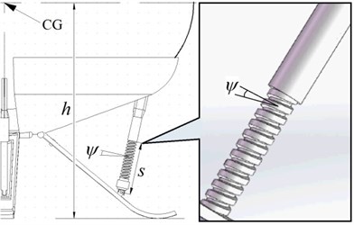
The actuating cylinder is composed of a motor and a screw mandrel. The analysis of the auto locking function of screw thread joint is based on the in equation [19]:
where , and are the thread angle, the static friction coefficient and the static friction angle of the screw thread joint of the actuating cylinder, respectively. Parameters of the actuating cylinder are shown in Fig. 8.
Fig. 8Parameters of the actuating cylinder
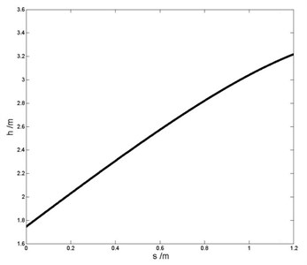
The functional relationship between the length of the actuating cylinder and the vertical distance from the skid plate to center-of-gravity are shown in Fig. 9.
Fig. 9Functional relationship between the length of the actuating cylinder and the vertical distance from the skid plate to center-of-gravity
3.4. Ground contact model
Most of the current research works about the VTOL vehicle dynamics paid more attention on the buffering performance but the interaction between soil and skid plates are not fully understood. In view of landing safety and passenger comfort, the lander is chosen to land on a soil terrain, which plays an important role in dynamic simulation. Ground contact force is studied in a soft-contact model [20]. Each skid plate has a vertex used for measuring the ground penetration depth and penetration velocity. Soil deforms under vertical force including loading process:, unloading process: and reloading process: . In all, different load states correspond to different pressure-deformation curves as shown in Fig. 10.
Fig. 10Response to repetitive load of a soil terrain
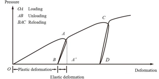
Based on the soil terrain described above, the pressure-deformation relationship during loading, such as , may be approximately by Bekker model [21]:
where is the deformation of soil; and are the pressure coefficient; and are the area and the radius of the skid plate, respectively.
The pressure-deformation relationship during both unloading and reloading, such as and , may be expressed approximately by a linear function which represents the average response of the terrain:
where and are the pressure and deformation during unloading or reloading, respectively; and are the pressure and deformation when unloading begins; is the pressure-deformation parameter representing the average slope of the unloading-reloading line , which is a function of the deformation where unloading begins:
where and are parameters representing the response of the terrain to repetitive loading and is the deformation where unloading begins, respectively.
4. Landing simulation
4.1. Three landing conditions
The dynamic model of the lander is established and implemented with the software ADAMS. The lander impacts the soil terrain at a vertical speed of 5 m/s, and then shock absorbers take actions in order to approximate a soft landing.
Landing simulation is performed for comparison between MALG and a traditional landing gear with the same configuration and structure parameters. All components of the traditional landing gear are assembled together and the actuating cylinders are all rigidly fixed so that they cannot relatively move. While landing on an incline surface, four feet of rigidly fixed landing gear (RFLG) touch the ground with 1-2-1 mode (the first condition) and 2-2 mode (the second condition), respectively. It is indicated that landing performance using 2-2 mode is better [22], so the slope angle of second condition is increased to 15 degrees in simulation. While landing on a horizontal terrain with a pit (the third condition), four feet of RFLG touch the ground with 3-1 mode (three legs touch the surface simultaneously first, and the leg above the pit touches the ground at last). In all cases studied in this paper, the four legs touch the oblique terrain together as MALG is used. The parameters of three landing conditions used in following simulation are given in Table 2.
Table 2Three landing conditions
Landing condition number | Surface slope angle (degree) | Surface’s pit depth (mm) | Touchdown speed (m/s) | Touchdown sequence of skid plates of RFLG | Touchdown sequence of skid plates of MALG |
1 | 10 | 0 | 5 | (1-2-1) | Together |
2 | 15 | 0 | 5 | (2-2) | Together |
3 | 0 | 600 | 5 | (3-1) | Together |
4.2. Simulation results
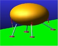
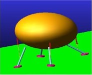
According to the controller decision tree in Fig. 4, simulation of near space travel lander is performed in different conditions including slope and concave terrain. Snapshots of the time history of slope landing implementing MALG on 10 degrees slope are shown in Fig. 11.
Simulation result shows that the lander with MALG can achieve 10 degrees slope while maintaining the capsule nearly horizontal. The landing speed and fuselage rotation angle in simulation are 5.1 m/s and 2.5 degrees, which are consistent with scaled test results in Table 1.
To analyze the difference of MALG and RFLG, the capsule’s overload as a function of time in different landing conditions are shown in Fig. 12.
Fig. 11Snapshots of the drop case implementing MALG on 10 degrees slope
a) Adjusting down
b) Touchdown
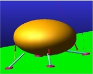
c) Peak compression
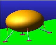
d) Buffering down
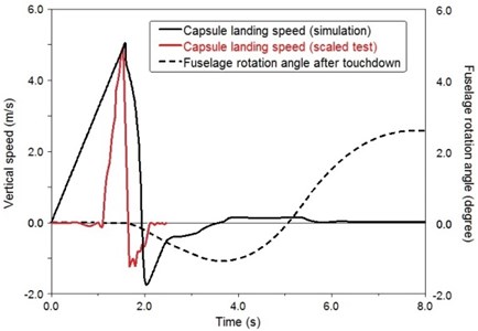
Fig. 12Comparison of capsule’s overload as a function of time
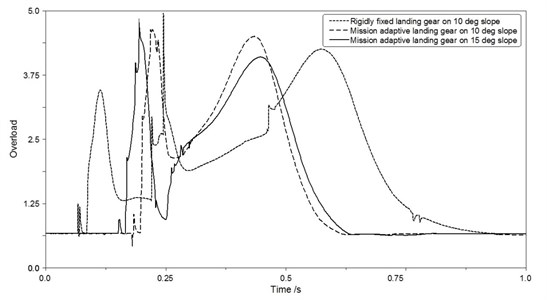
According to Fig. 12, maximum overload of the capsule using MALG on 15 degrees slope is less than the capsule implementing RFLG on 10 degrees slope. Simulation results show that MALG adopted can reduce maximum overload of slope landing. The curve of MALG only has two obvious maximum values which represent the moment of touchdown together of four feet and the moment of maximum compression of the shock absorbers, respectively. The curve of RFLG has three obvious maximum values because four skid plates touch the oblique terrain at different time.
The lander will inevitably have a trend of displacement after initial touchdown. In consideration of security, MALG adopted effectively stabilizes the position and rotation of the lander. More simulation results including displacement of center-of-gravity and rotation angle of the fuselage are shown in Table 3.
According to Table 3, the lander with RFLG eventually settles on the incline or uneven surface but undergoes significant translational motion along the ground due to the fuselage tilting away after touchdown. When MALG is adopted, displacements of the lander are all less than 1 m and rotation angles of the fuselage are all less than 3 degrees. The new design reduces maximum overload of the capsule in slope landing and ensures the value of maximum overload less than 5 in three conditions.
As the oleo-pneumatic shock absorber provides air spring force, one of the skid plates may bounce off slightly. Landing performances show that the overload and angular acceleration of the cabin have almost no change during the process of buffering and slight spin back, so the use of oleo-pneumatic shock absorbers is reliable.
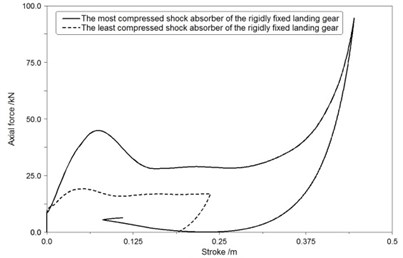
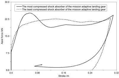
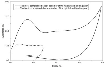
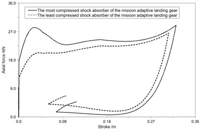
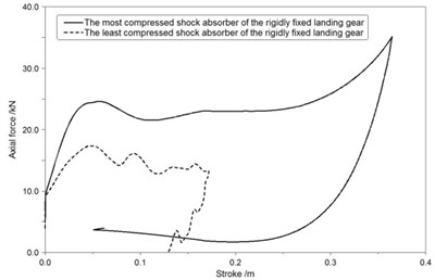
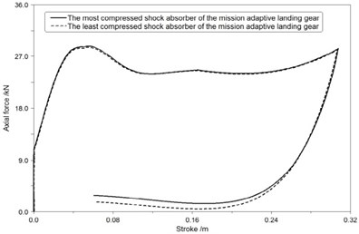
The axial force-stroke curves of shock absorbers of MALG and RFLG in three landing conditions are compared and presented in Figs. 13-15, respectively.
Table 3Simulation results
Landing condition number | Landing gear adopted | Touchdown sequence of skid plates | Displacement of center-of-gravity along -direction (mm) | Displacement of center-of-gravity along -direction (mm) | Fuselage rotation angle (degree) | Maximum overload of the capsule |
1 | RFLG | (1-2-1) | 6681 | 752 | 10.9 | 4.6 |
1 | MALG | Together | 645 | 174 | 2.3 | 4.9 |
2 | RFLG | (2-2) | 8270 | 893 | 11.2 | 4.8 |
2 | MALG | Together | 742 | 183 | 2.5 | 5.3 |
3 | RFLG | (3-1) | 923 | 315 | 7.1 | 4.4 |
3 | MALG | Together | 353 | 283 | 1.4 | 4.9 |
Fig. 13The axial force-stroke curve of shock absorbers in first landing condition
a) RFLG
b) MALG
Fig. 14The axial force-stroke curve of shock absorbers in second landing condition
a) RFLG
b) MALG
Fig. 13(a), Fig. 14(a), Fig. 15(a) show that the most compressed shock absorber of RFLG obviously has a low efficiency which is less than 60 % and a long stroke length which is more than 0.35 m in all conditions.
Fig. 13(b), Fig. 14(b), Fig. 15(b) show that efficiencies of the most and least compressed shock absorbers of MALG all more than 85 % during the landing process, and deviations of gear stroke lengths in different shock absorbers of MALG are all less than 0.03 m.
Based on the comparison of the axial force-stroke curves, maximum loads of the most compressed shock absorber are reduced by more than 24 % while using MALG in place of the RFLG. Landing performance illustrates the new design is adaptive and robust to uncertain conditions.
In some cases, the axial force decreases quickly to zero during the backward stroke, because the ground friction forces avoid the skid plates to move back to the initial position when the shock absorbers reset.
Fig. 15The axial force-stroke curve of shock absorbers in third landing condition
a) RFLG
b) MALG
4.3. Slope limit analysis
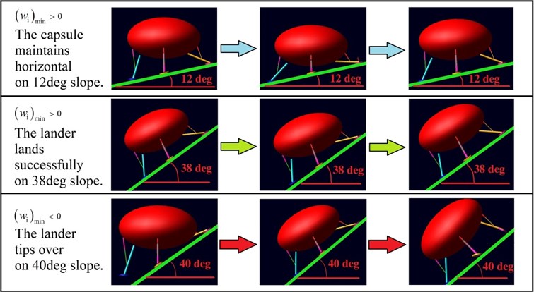
The slope limit must allow the vehicle lands safely without tipping over. On the basis of lander’s two-dimensional model in Fig. 7, the distance from center-of-gravity of the lander to the gravity line of the adjacent skid plate is used to determine the landing stability. The minimum value of during the landing indicates that the vehicle does not fall over during touchdown, otherwise the vehicle tips over.
Simulation results show that MALG can achieve 12 degrees slope while maintaining the capsule horizontal. The lander with MALG lands successfully on 38 degrees slope, and it tips over when the slope angle is increased to 40 degrees. The limit degree of slope angle is consistent with scaled test results in Table 1 that the vehicle tips over on 40 degrees slope. Snapshots of the drop cases implementing MALG on different slope terrains are shown in Fig. 16.
Fig. 16Snapshots of the drop cases implementing MALG on different slope terrains
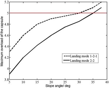
The primary factor affecting the slope limit for the lander is the passenger comfort degree. Two key factors affecting the passenger comfort degree are the capsule’s maximum overload and the capsule’s attitude angle after touchdown. Maximum overload and attitude angle of the capsule change with slope angle of the landing surface, which are shown in Fig. 17.
Fig. 17Maximum overload and attitude angle of the capsule change with slope angle
a) Maximum overloud of the capsule
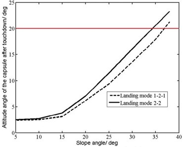
b) Attitude angle of the capsule after touchdown
The manned capsule’s maximum overload is required to be less than 5 as buffer seats are used to reduce passenger’s maximum overload further, and the manned capsule’s attitude angle after touchdown is required to be less than 20 degrees. According to Fig. 17, the slope limit for safe and comfortable landing is 31 degrees as MALG is used.
4.4. Comparison between MALG and other technologies
Compared with articulated robotic landing gear [12], MALG has some advantages:
1) The force transmission path of MLAG is better, as MALG uses the triangular structure consisting of a shock absorber, a strut and the capsule structure to bear the impact load, which is applied in the same direction with the shock absorber.
2) The vehicle with MALG has enough time to adjust before touchdown, as the controller instructs MALG to land after adjustment.
3) The vehicle with MALG is more suitable for manned capsule, as it only has two maximum overloads during landing which happen at the moment of touchdown and maximum compression of the shock absorbers. It is more comfortable for passengers that all legs touch the ground together and then all shock absorbers take actions to decrease the impact loads at the same time.
5. Conclusions
MALG is designed for VTOL aircraft such as a near space travel lander. The new design uses infrared distance sensors to measure the vertical distances from the ground directly beneath feet to the skid plates. Based on the data processed in the controller, actuating cylinders take actions and adjust the angles of main struts relative to the fuselage, ensuring that four skid plates touch the incline terrain at the same time. At last the shock absorbers work and absorb the kinetic and potential energy. The buffering process happens after the process of adjustment, and the axial forces of the actuating cylinder are in the same direction with the shock absorber, so the structure has rational mechanical behavior. The works of this paper including dynamic simulation and scaled test demonstrate that:
1) MALG enhances the capability of landing on oblique or uneven surface, and it only has two maximum overloads because four feet touch the irregular surface together and then the shock absorbers take action.
2) Compared with RFLG, MALG has better landing performance as maximum overload of the capsule carrying passengers can be reduced effectively, and efficiencies of shock absorbers increase with the decrease of the most compressed shock absorbers’ stroke length.
3) MALG can achieve 12 degrees slope while maintaining the capsule nearly horizontal. The lander with MALG lands successfully on 38 degrees slope, but it tips over when the slope angle is increased to 40 degrees. Considering limit of the capsule’s maximum overload and attitude angle, the slope limit for safe and comfortable landing is 31 degrees as MALG is used.
References
-
Weitz L. A., Stassen H. A New spacing algorithm to support near-term interval management operations. 14th AIAA Aviation Technology, Integration, and Operations Conference, 2014.
-
Conner J. P., Arena A. S. Near space balloon performance predictions. Proceedings of the 48th AIAA Aerospace Science Meeting Including the New Horizons Forum and Aerospace Exposition. 2010, p. 1-8.
-
Zagrai A., Cooper B., Schlavin J., et al. Structural health monitoring in near-space environment, a high altitude balloon test. Proceedings of the 9th International Workshop on Structural Health Monitoring, 2013, p. 10-12.
-
Miller Z., Evans A., Seyfert J., et al. Analysis of flight of near-space balloon. APS April Meeting Abstracts, 2015.
-
Desai P. N., Prince J. L., Queen E. M., et al. Entry, descent, and landing performance of the mars phoenix lander. Journal of Spacecraft and Rockets, Vol. 48, Issue 5, 2011, p. 798-808.
-
Gonzales A. A., Stoker C. R. An efficient approach for Mars sample return using emerging commercial capabilities. Acta Astronautica, Vol. 123, 2016, p. 16-25.
-
Manivannan V., Langley J. P., Costello M. F., et al. Rotorcraft slope landings with articulated landing gear. AIAA Paper, 2013, p. 2013-5160.
-
Carpenter J. D., Fisackerly R., Rosa D. D., et al. Scientific preparations for lunar exploration with the european lunar lander. Planetary and Space Science, Vol. 74, Issue 1, 2012, p. 208-223.
-
Parks R., Minelli R., Haase et al. S. Adaptive Landing Gear. WIPO, Switzerland, 2007.
-
Mikułowski G., Jankowski L. Adaptive landing gear: optimum control strategy and potential for improvement. Shock and Vibration, Vol. 16, Issue 2, 2009, p. 175-194.
-
Dumont E., Sippel M. Analysis of the attempt of launcher stage return by SpaceX’ Falcon 9. SpaceX Workshop, Paris, 2015.
-
Kim D., Costello M. Virtual model control of rotorcraft with articulated landing gear for shipboard landing. AIAA Guidance, Navigation, and Control Conference, 2016.
-
Kiefer J., Ward M., Costello M. Rotorcraft hard landing mitigation using robotic landing gear. Journal of Dynamic Systems, Measurement, and Control, Vol. 138, Issue 3, 2016, p. 031003.
-
Blanchard U. J. Evaluation of a Full-Scale Lunar-Gravity Simulator by Comparison of Landing-Impact Tests of a Full-Scale and a 1/6-Scale Model, NASA TN D-4474. Langley Research Center, Langley Station, Hampton, 1968.
-
Jr. Walton W. C., Here R. W., Leonard H. W. Studies of touchdown stability for lunar landing vehicles. Journal of Spacecraft, Vol. 1, Issue 5, 1964, p. 552-556.
-
Chen J., Nie H. Overloading of landing based on the deformation of the lunar lander. Chinese Journal of Aeronautics, Vol. 21, Issue 1, 2008, p. 43-47.
-
Wei X., Liu C., Liu X., et al. Improved model of landing-gear drop dynamics. Journal of Aircraft, Vol. 51, Issue 2, 2014, p. 695-700.
-
Abzug M. J. An unconventibial tricycle landing gear. 24th Atmospheric Flight Mechanics Conference, Guidance, Navigation, and Control and Co-located Conferences, 1999, http://dx.doi.org/10.2514/6.1999-4018.
-
Katthagen J. C., Schwarze M., Warnhoff M., et al. Influence of plate material and screw design on stiffness and ultimate load of locked plating in osteoporotic proximal humeral fractures. Injury, Vol. 47, Issue 3, 2016, p. 617-624.
-
Yang G. T. Soil Dynamics. China Building Material Press, Beijing, 2000.
-
Wong J. Y. Theory of Ground Vehicles. John Wiley & Sons, 2001.
-
Lin Q., Nie H., Chen J., et al. Soft landing impact simulation of lunar lander. Chinese Space Science and Technology, 2011.
Cited by
About this article
Mingyang Huang – mathematical model and writing. Hong Nie – instruction and guidance. Ming Zhang – dynamic simulation. Xiaohui Wei – project background support. Shuai Yue – scaled test.
