Abstract
Considering the tilt of the seal ring, the transient vibration response analysis model of the non-contact mechanical seal is presented. The model is consisted of the transient Reynolds equation, the equation of motion and the equation for solving the high order nonlinear dynamic coefficients of seal. The relative error of the high order nonlinear film force to the linear film force is also obtained. With Euler method, the characteristic parameters of the transient vibration response are obtained, which include the axial vibration displacements and the angle-swing of the static ring. The 14 nonlinear force and 14 nonlinear overturning moment dynamic coefficients for the non-contact mechanical seal are calculated. The results show that the influence of the damping effects of the sealed fluid between the seal gap on the axial vibration displacements and the angle-swing is linear. The film thickness distribution changes with the axial vibration of seal, which will lead to static ring swing, and the swing also can cause the axial vibration of the seal. With the increase of the nonlinear order, the relative error of the nonlinear film force decreases. All of the nonlinear film forces, the non-linear stiffness coefficient and damping coefficient decrease with the seal film thickness increases.
1. Introduction
As the key parts of important equipment, the non-contact mechanical seal is widely used in aerospace, energy, petrochemical and other fields, such as the petrochemical pump, turbine pump etc. [1-4]. Under the extreme working conditions, due to the axial vibration or shock, the mechanical face seals often occur transient deformation or destruction of the sealed surface, which will lead to the seal failure [2, 5, 6]. So, study on the vibration characteristics with the nonlinear factors (under the axial vibration or shock conditions) in transient process is one of the main contents of design a non-contact mechanical seal, the research results will provide the theoretical guide to assure the stable operation of the seal. However, most of the existing studies based on the commercial software are to analyze the steady state performance of the seal, mainly include seal’s static lubrication characteristics, such as the thickness of the film, the average temperature rise, heat distortion, etc. Such as Zhang Guoyuan carried out the sealing static performances [1], the non-contacting mechanical seal transient start-up separated speed [2] and the seal controllable [7]. Brunetiere N. studies steady-state hydrostatic model and thermal effect of the mechanical face seals [4, 8]. The studies on the nonlinear vibration response of the mechanical seal are few. The dynamics behavior of the seal in the rotor system has the great influence on the response of the system, and more and more researchers are engaged in developing the related model. Such as Zhang Wanfu developed a three-dimensional computational fluid dynamics model of a seal and investigated the influence mechanism of combined effects between bearings and seals on the dynamic characteristics of the rotor-bearing-seal system [9].
However, these studies have not considered the nonlinear dynamic characteristic under the condition of tilting and swing of seal. As the mechanical seal is applied in the harsh conditions, such as the rocket engine shaft seal discussed in this paper, the nonlinear dynamics problems of the seal caused by the axial vibration or shock of shaft are becoming more common. Moreover, the axial excitation originated from the vibration or shock is of the typical time-varying and dynamic characteristics. So, in order to better access to the seal dynamic characteristics, it needs to study its nonlinear transient response characteristics. But, the full nonlinear dynamics model of the seal and its solution are very complex, and the iteration steps are massive. For example, the axial force of shaft effects the vibration which leads to the seal gap changes; the changes of gap will cause the changes of the force and other static characteristics parameters.
As described above, due to the high order and nonlinear time-vary characteristics, the process of the full model solution is very time-consuming and difficult convergence. It is nearly impossible to obtain the full static and dynamics characteristics parameters in the limited time stage, which will lead the controllable of the seal is poor. Hence, it is necessary to simplify the existing complex models to get the nonlinear transient vibrations and meet the requirement of designing the controllable seal and obtaining the dynamic characteristics of the seal. Two methods are often applied in solving the high order nonlinear model. One is to reduce the high orders by the POD method [10] or the series expansion, the other is to build the database. The series expansion only included the previous orders is a rapid method for the transient solution, and the time-cost is short and the accuracy of this method also have higher. So, in this paper, the error of the full nonlinear models’ results and the series expansion results is analyzed. With the special case, the errors of the force and dynamic coefficients of the seal are obtained, the accuracy will be verified. The series expansion method for simplifying the full nonlinear model will help to obtain rapidly the transient response results and guide the design of the controllable seal [2].
In this paper, a model with considering the tilt of the seal ring is developed, and the transient vibration response based on this model by the series expansion is studied. The model is consisted of the transient Reynolds equation, the equation of motion. The coupled equations are solved and the second and higher order nonlinear dynamic coefficients of seal are obtained. In order to study the response characteristics of the seal induced by the external axial force (or the axial displace), the nonlinear response, the stiffness and damping coefficients of the noncontact mechanical face seal are obtained. Besides, the high order nonlinear terms (the relative error of each order of the nonlinear oil film force, nonlinear stiffness and damping coefficient) with the different axial displaces is also calculated.
2. Model of transient vibration response of the non-contact mechanical face seal
2.1. Transient Reynolds equation
For the non-contact mechanical seal, according to the N-S equation and continuity equation based on the fluid mechanics, the dimensionless Reynolds equation can be obtained under the condition of the corresponding hypothesis as follows [7, 11]:
where, the dimensionless parameters ˉh=h/hm,ˉr=r/(r2-r1)=r/B,ˉμ=μ/μ0,ˉp=ph2m/(μ0ΩB2), ˉ˙h=˙h/(Ωhm), r1, r2 and B are respectively seal ring outer, inner diameter and radial length, and subscript hm are identified as the thickness of the oil film under the static equilibrium position or the initial position of the non-contact mechanical face seal.
The dimensionless boundary conditions show as following:
where, Γ1 indicate the seal filler entrance, Γ2 indicate other boundary in addition to Γ1, Γ indicate all the boundary.
2.2. Transient motion equation
According to the second law of Newton dynamics, the dynamic equations and the equilibrium equations of the rotor and stator of the seal can be set up, as:
where, M indicate the sealing ring’s mass; Kz, K˙z respectively indicate the stiffness and damping coefficients of the oil film; F(t) is external axial load (at static equilibrium position, F(t)= 0); J indicate the inertia of rotor; and Kϕ, K˙ϕ respectively indicate the torque stiffness and damping coefficients of the oil film; N(t) is the external torque on the rotor (i.e. overturning moment).
From the Eqs. (3-4), we can conclude that the sealing rings (the rotor and stator) moment is independent of the tilting. Actually, that’s not true. The vibration effect of the seal will lead to the oil film thickness distribution, and the pressure distribution of the oil film is changed. As the result, the sealing ring is tilt because of the overturning moment. The same reason that the axial vibration will be caused by the sealing ring swing. These will be analyzed in the following section. However, the linear analysis is unable to solve the relationship between the movement and the swing of the sealing ring.
2.3. The sealing gap equation and the axial load with considering the tilting of seal
Seal gap control equation is shown as following:
where, h indicate oil film thickness, hp indicate the oil film thickness under the static equilibrium position, θp indicate the circumferential angle of the tilting status, ϕ indicate the tilt angle of the stator.
By integrating the pressure of the oil film load region in the sealing gap, the axial load capacity of the oil film can be obtained as follows:
According to the tilt of the mechanical seal, the overturning moment should also be considered as:
2.4. Second order nonlinear dynamic characteristics model
2.4.1. Second Order film gap thickness
Film thickness can be expressed under the disturbance condition as [11]:
-12rsin(θp-θ)sinϕ0(Δϕ)2,
where, z0 indicates the oil film thickness at the central point of the compensation unit, ϕ0 indicates the tilting angle of the static seal ring under the steady status, Δz indicates the incremental of z0 or h0, Δϕ indicates the incremental of ϕ0.
Under transient conditions:
=Δ˙z+rsin(θp-θ)cosϕ0Δ˙ϕ-rsin(θp-θ)sinϕ0(Δϕ)(Δ˙ϕ).
2.4.2. Second order seal opening force and overturning moment
Matrix of the transient oil film force under the sealing gap disturbance condition is shown as following:
+(Δz,Δ˙z,Δϕ,Δ˙ϕ)[12∂2F∂z212∂2F∂z∂˙z12∂2F∂z∂ϕ12∂2F∂z∂˙ϕ12∂2F∂˙z∂z12∂2F∂˙z212∂2F∂˙z∂ϕ12∂2F∂˙z∂˙ϕ12∂2F∂ϕ∂z12∂2F∂ϕ∂˙z12∂2F∂ϕ212∂2F∂ϕ∂˙ϕ12∂2F∂˙ϕ∂z12∂2F∂˙ϕ∂˙z12∂2F∂˙ϕ∂ϕ12∂2F∂˙ϕ2][ΔzΔ˙zΔϕΔ˙ϕ]
+0(Δz3,Δ˙z3,Δϕ3,Δ˙ϕ3).
Matrix of the transient oil film overturning moment under the sealing gap disturbance condition is shown as following:
+(Δz,Δ˙z,Δϕ,Δ˙ϕ)(12∂2N∂z212∂2N∂z∂˙z12∂2N∂z∂ϕ12∂2N∂z∂˙ϕ12∂2N∂˙z∂z12∂2N∂˙z212∂2N∂˙z∂ϕ12∂2N∂˙z∂˙ϕ12∂2N∂ϕ∂z12∂2N∂ϕ∂˙z12∂2N∂ϕ212∂2N∂ϕ∂˙ϕ12∂2N∂˙ϕ∂z12∂2N∂˙ϕ∂˙z12∂2N∂˙ϕ∂ϕ12∂2N∂˙ϕ2)(ΔzΔ˙zΔϕΔ˙ϕ)
+0(Δz3,Δ˙z3,Δϕ3,Δ˙ϕ3).
2.4.3. Second order nonlinear dynamic characteristic coefficients
The matrix form of the force-stiffness damping coefficients of the oil film can be expressed as:
+(Δz,Δ˙z,Δϕ,Δ˙ϕ)(12Kzz12Kz˙z12Kzϕ12Kz˙ϕ12K˙zz12K˙z˙z12K˙zϕ12K˙z˙ϕ12Kϕz12Kϕ˙z12Kϕϕ12Kϕ˙ϕ12K˙ϕz12K˙ϕ˙z12K˙ϕϕ12K˙ϕ˙ϕ)[ΔzΔ˙zΔϕΔ˙ϕ]
+0(Δz3,Δ˙z3,Δϕ3,Δ˙ϕ3).
With the Eq. (6), (11), (13), the nonlinear force-dynamic coefficients of the seal under the transient oil film disturbance condition can be obtained, as
Linear stiffness coefficients: Kz=I1[Pz], Kϕ=I1[Pϕ];
Linear damping coefficients: K˙z=I1[P˙z], K˙ϕ=I1[P˙ϕ];
Second order nonlinear stiffness coefficients: Kzz=I1[Pzz], Kϕϕ=I1[Pϕϕ];
Second order nonlinear cross stiffness coefficients: Kzφ=Kφz=I1[Pzφ];
Second order nonlinear damping coefficients: K˙z˙z=I1[P˙z˙z]=0, K˙ϕ˙ϕ=I1[P˙ϕ˙ϕ]=0;
Second order nonlinear cross damping coefficients: K˙z˙φ=K˙φ˙z=I1[P˙φ˙z]=0;
Nonlinear stiffness damping coupling coefficients:
Kz˙z=K˙zz=I1[Pz˙z], Kz˙ϕ=K˙ϕz=I1[Pz˙ϕ], K˙zϕ=Kϕz=I1[P˙zϕ], Kϕ˙ϕ=K˙ϕϕ=I1[Pϕ˙ϕ];
To all the above formula, the following formula is defined, as:
The matrix form of the overturning moment-stiffness damping coefficients of the oil film can be expressed as:
+(Δz,Δ˙z,Δϕ,Δ˙ϕ)(12Vzz12Vz˙z12Vzϕ12Vz˙ϕ12V˙zz12V˙z˙z12V˙zϕ12V˙z˙ϕ12Vϕz12Vϕ˙z12Vϕϕ12Vϕ˙ϕ12V˙ϕz12V˙ϕ˙z12V˙ϕϕ12V˙ϕ˙ϕ)(ΔzΔ˙zΔϕΔ˙ϕ)+0(Δz3,Δ˙z3,Δϕ3,Δ˙ϕ3).
With the Eq. (7), (12) and (14), the linear and nonlinear overturning moment dynamic coefficients of the oil film are obtained, as
Linear stiffness coefficients: Vz=I2[Pz], Vφ=I2[Pφ];
Linear damping coefficients: V˙z=I2[P˙z], V˙φ=I2[P˙φ];
Second order nonlinear stiffness coefficients: Vzz=I2[Pzz]Vφφ=I2[Pφφ];
Second order nonlinear cross stiffness coefficients: Vzφ=Vφz=I2[Pzφ];
Second order nonlinear damping coefficients: V˙z˙z=I2[P˙z˙z]=0, V˙φ˙φ=I2[P˙φ˙φ]=0;
Second order nonlinear cross damping coefficients: V˙z˙φ=V˙φ˙z=I2[P˙z˙φ]=0;
Nonlinear stiffness damping coupling coefficients:
Vz˙z=V˙zz=I2[Pz˙z], Vz˙ϕ=V˙ϕz=I2[Pz˙ϕ], V˙zϕ=Vϕ˙z=I2[P˙zϕ], Vϕ˙ϕ=V˙ϕϕ=I2[Pϕ˙ϕ];
To all the above formula, the following formula is defined as:
By the Eq. (13-14), with the given conditions, the number of the force and the overturning moment dynamic characteristic coefficients is 20, and considering the symmetric coefficients, the number of the respectively coefficients is 14. Besides, the following conclusions can be obtained as,
(1) The nonlinear damping coefficients are equal to 0. That means that the effect of oil film damping on sealing swing are linear relations. It is because that the transient term ∂h/∂t in the transient Reynolds equations is a first-order.
(2) The seal axial vibration affects the oil film thickness distribution, and the oil film pressure distribution, which will lead to the sealing ring swing. The converse is also true, seal swing will also cause the axial vibration.
2.4.4. The second order nonlinear transient motion equation
Considering the inertia of the sealing ring, the stiffness and damping coefficients are substituted into the Eq. (3) and (4), the second order nonlinear non-dimensional axial vibration equation of the sealing ring can be obtained as:
+ˉKzΔˉz+ˉKϕΔˉϕ+12ˉKzzΔˉz2+12ˉKϕϕΔˉϕ2+ˉKzϕΔˉzΔˉϕ=0,
where, ˉM indicates the non-dimensional mass of the seal ring, ˉM=MΩh3m/(μ0B4).
The second order nonlinear dimensionless motion equations under the oscillating condition:
+ˉVzΔˉz+ˉVϕΔˉϕ+12ˉVzzΔˉz2+12ˉVϕϕΔˉϕ2+ˉVzϕΔˉzΔˉϕ=0,
where, ˉJindicates non-dimensional rotational inertia of seal ring, ˉJ=JΩh3m/(μ0B6).
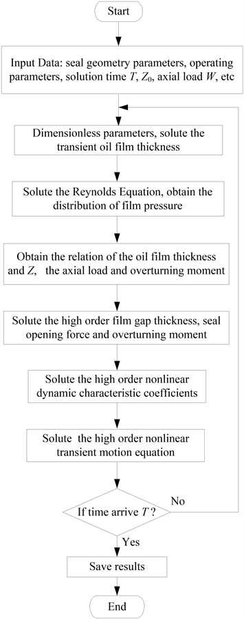
So, the schematic diagram of the mathematical model is shown in Fig. 1. The model includes the transient Reynolds equation, the transient motion equation and the sealing gap equation. Based on the existing softwares [1, 10], the model is solved. The results of the higher (second, third, and fourth) order film gap thickness, seal opening force, overturning moment, dynamic characteristic coefficients will be obtained.
Fig. 1Schematic diagram of the mathematical model
2.4.5. Error estimation of the higher order nonlinear terms
From the Eq. (13), the higher order components of the oil film force is neglected and the truncation error of the transient oil film force occurs. So, in order to understand the accuracy of the transient oil film force, it is necessary to analyze the influence of the truncation error and the high order nonlinear terms on the transient oil film force. The influence degree can be determined by the relative error of the accurate value of the oil film force to the transient oil film force:
where, ˉF is the oil film force accurate value calculated by solving Eq. (6), ˉFm is the transient oil film force, ΔFn is a function of Δh as shown in Eq. (11). n denotes the high order number, which could be determined according to the oil film thickness and the relative error.
Refer the Eq. (13), the transient oil film force Fm is a function of the displacement and velocity of the sealing ring. When the seal system is disturbed, the higher order nonlinear oil film force can be expanded by Taylor Function as follows:
+12∂2F∂˙z2Δ˙z2+⋯+∂2F∂z∂˙zΔzΔ˙z+12∂3F∂z2∂˙zΔz2Δ˙z+16∂4F∂z3∂˙zΔz3Δ˙z+⋯.
Or as follows:
+Kz˙zΔzΔ˙z+12Kzz˙zΔz2Δ˙z+16Kzzz˙zΔz3Δ˙z+⋯,
where, F0 indicates the oil film force under steady state; Knindicates the n-order linear and nonlinear dynamic characteristic coefficients, n can be z, zz,… , ˙z, ˙z˙z,…, z˙z, zz˙z, zzz˙z and:
K˙z˙z=∂2F∂˙z2,Kz˙z=∂2F∂z∂˙z,Kzz˙z=∂3F∂z2∂˙z,Kzzz˙z=∂4F∂z3∂˙z.
The n-order non-dimensional nonlinear transient oil film force ˉFm can be expressed as following:
+ˉKz˙zΔˉzΔˉ˙z+12ˉKzz˙zΔˉz2Δˉ˙z+16ˉKzzz˙zΔˉz3Δˉ˙z+⋯=ˉKnzΔˉz+ˉKn˙zΔ˙z,
where, ˉKnz indicates the dimensionless nonlinear stiffness coefficient of oil film force:
ˉKn˙z indicates the dimensionless nonlinear damping coefficient of oil film force:
The dimensionless quantity of the higher order stiffness and damping coefficient of oil film force is shown as following:
K˙z=ˉK˙zμL3Bh3m,Kz˙z=ˉKz˙zμL3Bh4m,Kzz˙z=ˉKzz˙zμL3Bh5m,Kzzz˙z=ˉKzzz˙zμL3Bh6m.
3. Case study
3.1. Research object and results of the stiffness and damping coefficients
The geometrical parameters of the mechanical seal are shown in Table 1.
The dimensionless values of the nonlinear dynamic characteristic coefficients are calculated as shown in Table 2.
Table 1Geometrical parameters of the mechanical seal
Items | Value |
Inside diameter r1 (m) | 0.125 |
Outer diameter r2 (m) | 0.21 |
The lilting angle of the static ring θs (rad) | 0.45 |
The tilting circumferential angle θp(rad) | 0.26 |
Fluid viscosity μ0 (Pa·s) | 0.04315 |
Fluid Density ρ (kg/m3) | 998 |
Sealing rotatory speed Ω (r/min) | 3500 |
Seal axial load W (kg) | 18000 |
Table 2Dynamic characteristic coefficients
Dynamic characteristic coefficient of force | Dimensionless value | Dynamic characteristic coefficient of moment | Dimensionless value |
ˉKz | –1.312 | ˉVz | –0.001 |
ˉK˙z | –6.161 | ˉV˙z | –0.044 |
ˉKφ | 12.608 | ˉVφ | –0.142 |
ˉK˙φ | –0.049 | ˉV˙φ | –0.734 |
ˉKzz | 2.485 | ˉVzz | –0.016 |
ˉKz˙z | 17.568 | ˉVz˙z | 0.006 |
ˉKzφ | –35.972 | ˉVzφ | 0.871 |
ˉKz˙φ | –0.036 | ˉVz˙φ | 2.001 |
ˉK˙z˙z | 0.000 | ˉV˙z˙z | 0.000 |
ˉK˙zφ | 0.042 | ˉV˙zφ | 2.843 |
ˉKz˙φ | 0.000 | ˉV˙z˙φ | 0.000 |
ˉKφφ | 0.314 | ˉVφφ | –5.911 |
ˉKφ˙φ | 2.839 | ˉVφ˙φ | –0.058 |
ˉK˙φ˙φ | 0.000 | ˉV˙φ˙φ | 0.000 |
3.2. Results of transient vibration response
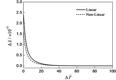
In this paper, the Euler method is used to solve the Eqs. (15-16), and the dimensionless transient vibration response with time is obtained, which as shown in Fig. 2 and 3. The initial conditions are Δˉz=0.3, Δˉϕ=0.0. The dimensionless linear and nonlinear increment of the oil film thicknesss (Δˉz) in the situation of the static ring central point with the time are shown in Fig. 2. The changes of the linear and nonlinear tilting angle of the static ring with the time are shown in Fig. 3. From Fig. 2, the displacement of the sealing ring decreases with time because that the damping of the oil film acting on the sealing ring is over damped. From Fig. 3, the maximum amplitude of the static ring swing quickly reach, then a non-periodic exponentially peristalsis occur, so the static ring motion is also the over damped motion.
When the initial conditions are Δˉz=0.0 and Δˉϕ=1.0E-3, the results of the transient vibration response is shown in Fig. 4 and 5. The displacement of the sealing ring is fast to reach the maximum amplitude, and then is a non-periodic creep in the exponential law, and shown in Fig. 4. The amplitude of the static ring is gradually decreased with time, as shown in Fig. 5. The motion of the sealing ring and the static ring are also the damping motion. The results shown that the vibration of the seal ring can cause the static ring swing, the static ring can also cause the seal ring vibration.
Fig. 2Axial vibration response (Δz-=0.3, Δϕ-=0.0)
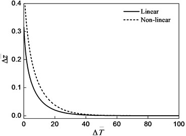
Fig. 3Swing response (Δz-=0.3, Δϕ-=0.0)
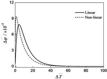
Fig. 4Axial vibration response (Δz-=0.0, Δϕ-=0.001)
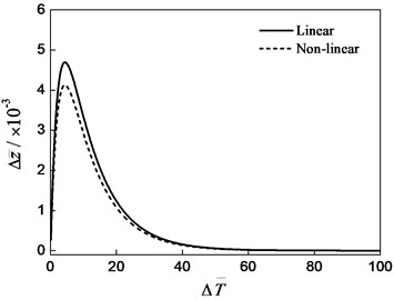
Fig. 5Swing response (Δz-=0.0, Δϕ-=0.001)
3.3. The high order non-dimensional nonlinear transient oil film force
The 4 order non-dimensional nonlinear transient oil film force ˉF is:
-6.161(Δˉ˙z)+(17.568)(Δˉz)(Δˉ˙z)--12(2.450)(Δˉz)2(Δˉ˙z)+16(9.734)(Δˉz)3(Δˉ˙z).
The 4 order non-dimensional nonlinear steady oil film force ˉFm is:
m=1,…,4.
The dimensionless nonlinear stiffness ˉKnz and damping coefficient ˉKn˙z of the steady state oil film force are respectively as follows:
ˉKn˙z=6.161-17.568(Δˉz)+12(2.450)(Δˉz)2-16(9.734)(Δˉz)3.
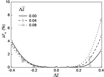
Fig. 6 is the relative error of the high order (first, second, third and fourth order) nonlinear oil film force to the accurate value of the oil film force. As shown in Fig. 6, the relative error of the nonlinear oil film force change with the change of the oil film thickness Δˉz and rotor motion speed Δˉ˙z; as the number of the order increase, the error decreases. The increase of oil film thickness and the rotor speed leads the error increase, which shows that the nonlinear characteristic of the nonlinear oil film force is very obvious.
Fig. 6The relative error of the high order nonlinear oil film force
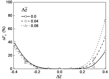
a) First order error
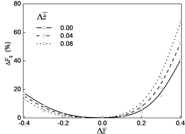
b) Second order error
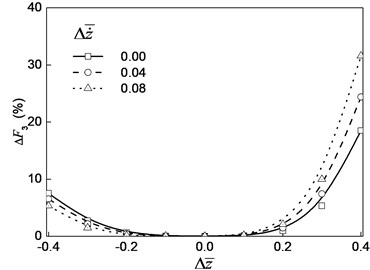
c) Third order error
d) Fourth order error
Fig. 7 is the curve of the relative error of the high order relative errors of the nonlinear oil film force with the change of the oil film thickness. Fig. 8 is a curve of the different higher-order dimensionless nonlinear oil film force with the change of the oil film thickness. From Fig. 7 and Fig. 8, we can see that with the increase of the order number, the relative errors of the oil film force decrease. With the increase of oil film thickness, the nonlinear oil film force decreases.
For the relative error value of the 4 order ΔF4 just only is 4.8 % on the condition of Δˉz= –0.4. Therefore, the 4 order nonlinear oil film force can be used to meet the requirements of high precision. The second order nonlinear force can be used if the accuracy requirement is not more than 10 % when the change of the film thickness Δˉz is no more than 30 %. The error of the first order linear oil film force to the fourth order nonlinear force is larger when the oil film thickness is more far away the static equilibrium position.
Fig. 7The relative error of the oil film force with the change of oil film thickness
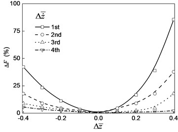
Fig. 8Oil film force curve with oil film thickness
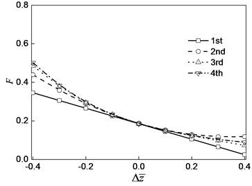
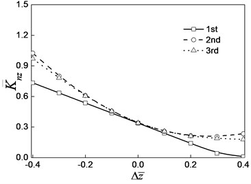
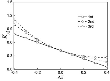
Fig. 9 is the dimensionless nonlinear stiffness coefficient ˉKnz and damping coefficient ˉKn˙z curve with the change of the oil film thickness increment.
As shown in Fig. 8 and Fig. 9, with the increase of oil film thickness, the nonlinear oil film force, nonlinear stiffness coefficient and damping coefficient decrease.
Fig. 9Variation curve of the damping coefficient of the steady state oil film force with the increment of oil film thickness
a) Dimensionless nonlinear stiffness coefficient
b) Non-dimensional nonlinear damping coefficient
4. Conclusions
1) The transient nonlinear vibration response model of the non-contact mechanical seal considering the tilt of the seal ring conditions is proposed. The model includes the transient Reynolds equation, the equation of motion and the equation for solving the high-order nonlinear dynamic (stiffness and damping) coefficients of seal.
2) With the Euler method, the performance parameters of the transient vibration response are obtained, which include the axial vibration displacements and the swing-angle of the static ring. The 14 second order nonlinear force and 14 second order nonlinear overturning moment dynamic coefficients for the non-contact mechanical seal are calculated.
3) A special case is analyzed. The results show that the influence of the damping effects of the sealed fluid between the seal gap on the axial vibration displacements and the angle-swing is linear. The film thickness distribution changes with the axial vibration of seal, which will lead to static ring swing. With the increase of the order number of the nonlinear oil film force, the relative error of the oil film forces decrease. With the increase of the film thickness, the nonlinear oil film force, nonlinear stiffness coefficient and damping coefficient decrease.
References
-
Zhang G. Y., Zhao W. G., Yan X. T. Theoretical and experimental study on characteristics of water-lubricated double spiral grooved seals. Tribology Transactions, Vol. 54, Issue 3, 2011, p. 362-369.
-
Zhang G. Y., Zhao W. G. Design and experimental study on the controllable high-speed spiral groove face seals. Tribology Letters, Vol. 53, Issue 2, 2014, p. 497-509.
-
Zhang G. Y., Zhao W. G., Yan X. T. Experimental study on the water lubrication of non-contacting face seals for turbopumps. Industrial Lubrication and Tribology, Vol. 66, Issue 2, 2014, p. 314-321.
-
Brunetière N., Galenne E., Tournerie B. Modelling of non-laminar phenomena in high reliability hydrostatic seals operating in extreme conditions. Tribology International, Vol. 41, Issue 4, 2008, p. 211-220.
-
Slawomir B., Andriy V., et al. A parametric and dynamic analysis of non-contacting gas face seals with modified surfaces. Tribology International, Vol. 94, Issue 1, 2016, p. 126-137.
-
Shun C. L., Xian L. Z. Analyses of both steady behavior and dynamic tracking of non-contacting spiral-grooved gas face seals. Computers and Fluids, Vol. 88, Issue 3, 2013, p. 326-333.
-
Zhang G. Y., Zhao W. G., Chen Y. Research on the active controllable and separation mechanics of the non-contact hydrostatic mechanical seal. Journal of Aerospace Power, Vol. 29, Issue 10, 2014, p. 2515-2522, (in Chinese).
-
Brunetiere N., Apostolescu A. A simple approach to the thermos Elasto Hydro Dynamic behavior of mechanical face seals. Tribology Transactions, Vol. 52, Issue 2, 2009, p. 243-255.
-
Zhang W., Yang J., Chun L. Synchronous and sub synchronous vibration under the combined effect of bearings and seals: numerical simulation and its experimental validation. Journal of Vibroengineering, Vol. 17, Issue 2, 2015, p. 662-673.
-
Zhang G. Y., Zhao W. G., Yan X. T. Principle and simulation for real-time monitoring of the non-contact face seal based on POD model. Hangkong Xuebao/Acta Aeronautica et Astronautica Sinica, Vol. 33, Issue 2, 2012, p. 354-361, (in Chinese).
-
Pinkus O., Sternlicht B. Theory of Hydrodynamic Journal Bearings. McGraw-Hill, New York, 1961.
About this article
This work was supported by National Natural Science Foundation of China (Project No. 51575418, 51205314), Natural Science Foundation of Shaanxi Province of China (No. 2014JQ7252).

