Abstract
Shock absorbers are intended for developing forces providing the elimination or reduction of the amplitude of cars or their parts fluctuations. On the CIS railroads, the wedge-type shock absorber became the most wide-spread in trucks of freight cars. In friction shock absorbers, the friction force arises in vertical and horizontal movements of the absorber wedges rubbing on friction plates fixed on the columns of the truck sidewalls. In the article, the modeling of dynamic characteristics of a freight car with the optimized parameters of the wedge-type shock absorber is performed. The modeling is performed by means of the software complex for studying the problems of dynamics of rail vehicles: “The universal mechanism”. A dynamic and block diagram of the dynamic model of the car platform, as well as of the mathematical model for studying the friction force and interaction of contact power elements, accounting the creep forces in contact by means of the FASTSIM algorithm based on the Kalker linear theory, is developed. The obtained results of modeling of an eight-wheel freight car with modernized frictional wedges show that in the truck modernization it is expedient to provide additional devices, for example a frictional shock absorber in the central step of suspension. The results of the carried out study prove the expediency of using for the upgraded truck of 18-100 model the design of M1816.06.000 SB, M1819.00.000 SB wedges, at this it is recommended to accept rigidity of elastic elements of these wedges equal to 1.1 kN/mm that is a compromise solution for the safe car movement in the empty and loaded modes.
1. Introduction
A wedge-type frictional shock absorber became the most wide-spread in the trucks of freight cars. The principle of its action is shown in, Fig. 1. It consists of two wedges 2 on which truck bolster 1 rests; in this place, the truck bolster has inclined surfaces (it is shown by the green trapeze). Owing to the inclined surface, the vertical force is decomposed into two components [1]. The horizontal component generates the friction force between the wedge and special friction plate 3. Owing to friction the fluctuations are absorbed [2, 3].
The wedge-type shock absorber having friction forces proportional to movements, but different values for the descending and ascending movements, is used practically in all trucks of freight cars [4]. In this absorber, the friction forces arise in relative vertical and horizontal movements of the rubbing surfaces of wedges 2 on the friction plates 3 fixed on the columns of the truck side frames. Therefore, wedge-type shock absorbers can absorb vertical and horizontal fluctuations [6, 7]. They are characterized by the design simplicity, reliability. The frictional wedges are established on the extreme springs of the spring set in freight cars trucks.
2. Materials and Methods
As a result of wear of the friction plate surfaces, wedge and truck bolster, the frictional wedge position relative to the truck bolster is changed, i.e. the wedge moves up, and its basic planes are established above the basic bearing surface of the truck bolster. In operation, the difference between the level of the wedges and the truck bolster fluctuates in a significant degree from –10 to +20 mm (see Figs. 1, 2).
Fig. 1Working principle of wedge-type shock absorber. 1 – bolster, 2 – wedge; 3 – friction strip
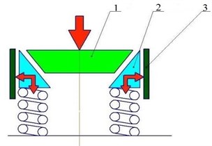
Fig. 2Possible positions of frictional wedges in truck
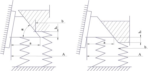
– angle to the horizontal plane of the wedge surface located on the part of the bolster; – width of the hole in the side frame for mounting spring group; – height under-wedge;
– overstating height of the wedge; – the thickness of the bottom of the wedge; – the thickness of the bottom of the bolster.
When setting the wedge above by 12 mm, the wedge friction force of the absorber decreases by 30-35 % in a loaded car, and in an empty car, the complete wedges unloading occurs. It leads to deterioration of the process of clearing vertical fluctuations, the growth of amplitude of fluctuations, and consequently of stresses into the body elements [8].
The position of wedges is determined by the distance between the friction surfaces of friction plates, as well as by the wedges and the truck bolster dimensions. Then the position of the bearing surface of the wedge relative to the bearing surface of the truck bolster will be determined by the expression:
– width of the hole in the side frame for mounting spring group (Fig. 2); – the thickness of the bottom of the wedge; – the thickness of the bottom of the bolster; – angle to the horizontal plane of the wedge surface located on the part of the bolster.
For the purpose of extension of the wedge-type absorber service life for new or repaired trucks, it is expedient to select the wedges and the bolster with large completeness. It can be performed by selecting wedges and truck bolsters so that there is observed the inequality:
– the thickness of the bottom of the wedge; – the thickness of the bottom of the bolster; – width of the hole in the side frame for mounting spring group (Fig. 2).
Proceeding from this, the length of the wedge base (completeness) is to be, for example, no less than 227 mm when releasing from the depot repair of one kind of wedges. When assessing the impact of actions for the truck modernization on dynamic car characteristics according to the specification, trucks, which are operated as a part of a long-base car platform of 13-2118 model, are considered there. The car platform is intended for transportation of large-capacity containers [5]. The platform includes a frame, two-axis trucks of 18-100 model. After selecting a 13-2118 model car platform as the object of studying, the impact on dynamic characteristics of actions for modernization of the truck is caused by the axial load in the loaded state close to the most admissible one, and the low car container, as well as the considerable car base effecting the dynamics when passing curved alignments. The main truck parameters are presented in Table 1.
Table 1Main parameters of 18-100 model truck
Weight, kg | 4800 |
Base, mm | 1850 |
Distance between the axes of the spring set, mm | 2036 |
Distance from the level of the rail heads to the level of the thrust bearing in the free state, mm | 803 |
Rigidity of suspension, kN/mm | 7800 |
Distance between the axes of bearings, mm | 1524 |
Constructive speed, km/h | 120 |
The assessment of the impact of actions for the 18-100 model truck modernization on its dynamic qualities is carried out on the basis of mathematical modeling of the car movement.
The modeling is carried out using the software complex of the dynamics modeling of body systems “The universal mechanism” developed in the PEI of HPT “Bryansk State Technical University” that is actively used for studying the problems of dynamics of rail vehicles at enterprises both in Russia and abroad [2, 3].
The dynamic solid-state model of the car platform of 13-2118 model see Fig. 3(a) presents a frame in the form of a rigid body, Pos. 2, with real geometrical and inertial characteristics, connected by contact elements and rotary hinges with subsystems “Truck”, Pos. 1.
Fig. 3Dynamic model of car platform: 1 – trolley; 2 – wagon frame; 3 – load
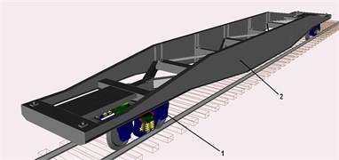
a) Empty car model
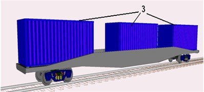
b) Car model loaded with three 20-foot containers
In the analysis of dynamic characteristics of a completely loaded car, its loading with three not completely loaded 20-foot containers of 23 t gross weight is considered see Fig. 3(b). With the specified scheme of loading, the allowed axial loading of 23.5 t/axis is completely realized. The containers installed at platform in the dynamic model are presented in the form of rigid bodies, Pos. 3, with the real inertial characteristics connected to the frame by special contact elements describing the interaction of the containers fittings with the platform frame support.
The containers are installed at the platform frame by means of contact elements defining the interaction of the container with the platform frame in the vertical plane and in the horizontal plane (longitudinal and cross directions) by contact elements. The power element corresponds to contact interactions of a pair of bodies where a set of points contacts with one body and the other one with the boundless plane determined by one point and an external normal [2]. Contact forces are equal to zero if the distance between the point and the plane- is positive (there is no contact). In the presence of contact, there is an interaction force having two components: the normal reaction directed to the normal to the plane, and the friction force lying in the contact plane. For the normal reaction, a linear viscoelastic model is used:
where , are constant coefficients of rigidity and dissipation of the contact interaction. The mathematical model of the friction force in the mode of sliding has the following form:
where is the vector of sliding speed; is the coefficient of friction sliding.
In case of a direction change of the sliding speed vector into the opposite one, the coupling mode is realized which mathematical model has the form:
where is the value of the friction force vector fixed in the transition from the sliding mode to the coupling mode; , are the initial and the current values of the vector connecting the point that describes an endless plane and the projection on the point contact plane that describes the contacted body. The linear power element connects two points with the specified coordinates belonging to two different bodies. In the course of changing positions of the points relative to each other in the element, the efforts which values at the reduction to the element attachment point to the second body in the coordinates of the first body are determined by the following expression, emerge:
where is the force emerging in the element; is a stationary value of the force; , are the element rigidity and relative movement of the point to the direction of the vector; , are the angular rigidity of the element and the relative rotation of the second body relative to the j vector. Wedge-type shock absorbers are presented in the form of rigid bodies with real inertial characteristics. The interaction of the wedge-type shock absorber with the truck bolster is modeled by the power contact “point-plan” element located in the zone of the auxiliary friction surface. The interaction of the wedge-type shock absorber with the side frame is also modeled by the contact power elements located in the zone of the main plane of friction. Contact interactions in the cross direction between the truck bolster and the side surface of the wedge and the side frame of the truck take into account the allowed by the truck design gaps in the cross direction. Side frames of the truck are modeled by rigid bodies with real inertial characteristics. When modeling the movement of the car hitch the elastic dissipative characteristics of the top structure of the way (Pos. 14, 15) are accepted according to the operation recommendations [4] for the summer period at a good condition of the way and rails of the P65 type (Version I) of 25 m long laid on wooden cross ties and the crushed-stone ballast.
The contact interaction of a wheel with a rail is modeled taking into account the possibility of point-to-point contact (around driving and on the wheel crest), the accounting of creep forces in contact is carried out using the FASTSIM algorithm based on the Kalker linear theory [5] and realized in the UM software complex. The advantage of the algorithm has a sufficiently high speed of calculation, accounting the spin and the elementary geometrical properties of the contacting surfaces (curvature radiuses). The algorithm is used in the conditions of the contact for calculating the creep forces at both points, taking into account that profiles of the wheel and the rail are not worn-out.
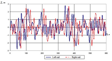
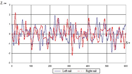
The car movement modeling is considered taking into account micro roughness’s of the way. The formation of casual way roughness is made based on the function of spectral density of the equivalent design roughness in the vertical and horizontal directions determined for speeds of the car movement to 120 km/h by the technique specified in RD 32.68-96 [6]. According to the range of frequencies from 0 to 10 Hz, the function of spectral density of the equivalent design roughness can be determined by the formula the largest transport perturbations occur in the frequency range of 1-10 Hz, which are the central frequency suspension undercarriage of the loading platform oscillations:
where , , , , parameters for modeling the spatial disturbances in the frequency range of 0-10 Hz, taken in accordance with [6]; is the car movement speed, m/s; is the disturbing frequency. The index value is selected depending on the ratio between the frequency f and the values of and : 1 at ; 2 at ; 3 at , where , is the disturbing frequency from 0 to 10 Hz:
The accounting of assessing spectral densities of space disturbances considering variability of the way condition is performed by the following equation:
where is, the quintile corresponding to the probability of the normal law of distribution accepted equal to ; is the coefficient of the equivalent surface mean square deviation variation taken into account.
The discrete realization of a random process with a set function of spectral density is formed according to the dependence specified in the work [7]:
where is a step of frequency discretization; is the value of spectral density at frequency ; is a random value with the probability density . The value of the random value is determined by the equation:
where is a random number from 0 to 1 obtained using the program sensor of random numbers obtained using a random number generator in the software package universal mechanism (UM). When forming roughness, the step of discretization was accepted equal to Hz. At this the number of points in realization made .
As a result of simulation on the vertical and horizontal analytical dependence microroughness’s stated above are obtained paths that are shown in Fig. 4, the blue marked microroughness’s of the left rail, and red - the right rail.
Fig. 4Micro roughness of rail way
a) Vertical
b) Horizontal
When determining dynamic characteristics of the car platform, the following modes of operation were considered:
car movement on the direct part of the way with speeds from 20 to 120 km/h with a step to 20 km/h;
car movement in curves with the radius R equal to 300, 500, 700 and 1200 m. In the present article, three options of modernization of wedge-type shock absorbers of the 18-100 model truck are considered. The purposes of modernization of shock absorbers are:
compensation of the rubbing surfaces in use wear;
provision of a constant value of friction forces in interfaces of the wedge to the truck bolster and the friction plate in the loaded and empty state.
The practice of operation of 18-100 model trucks shows that wear of the wedge is uneven. On the vertical frictional surface of the wedge, the maximum wear takes place in the lower part. The friction plate, on the contrary, wears out in the top part. At the maximum wear of the specified vertical surfaces, the wedge withdrawal is possible from the contacting surfaces (the wedge “somersaults”) [8-12]. The initial admissible non-adhering to the bottom (a gap) even with a newly made wedge is allowed to 2 mm, and when releasing from the depot repair to 4 mm. The proposed design permits to compensate the allowable gaps (and wear in operation) and to sustain the wedge raising of no more than 5 mm for all the term of operation between planned types of repair as specified in the standard documentation. When slips are used, a longer between-repairs operational period of the proposed wedge design is possible [15-18]. The second option of the wedge design proposed by the “Customer” is “A frictional wedge with an elastic element and wear proof overlays of M 1816.06.000 SB”. The third version of the wedge-type shock absorber is “A frictional wedge with an elastic slip of 1819.00.00 SB”. The design of the wedge is similar to the design of the frictional wedge of M 1816.06.000 SB; the replacement of an elastic polyurethane element by a spring is a distinctive feature.
Spring 4 drawing in slip 2 develops a possibility of obtaining a constant friction force on the wedge friction surfaces with the truck bolster and the friction plate of the truck side frame. The wedge advantage in comparison with the used design is the same as in M1816.06.000 SB wedge. The analysis of the working capacity and selection of rational parameters of options of modernization of the wedge-type shock absorber of the 18-100 model truck is carried out on the basis of mathematical modeling of interaction of the wedge elements with the truck bolster and the friction plate of the side frame using the developed test models (see Fig. 5). The test model presents a side frame 1 of the truck in the form of a rigid body which is rigidly fixed in space in all degrees of freedom. The truck bolster 2 presented in the form of a rigid body with real inertial characteristics having one forward degree of freedom in the vertical direction is connected to the side frame of the truck through special linear power spring elements 3 described in Section 2. In addition, through special power spring elements 3 and power contact elements between the friction plate and the main surface of friction, there is an interaction with the side frame solid-state models of wedges. Solid-state models of wedges also interact with inclined surfaces of the truck bolster through contact power elements [13]. Possible movement of models of wedges in the cross direction relative to the truck bolster and the side frame are limited within the admissible gaps to contact power elements [14]. The truck bolster in the truck central plate zone is affected by the revolting harmonious effort P causing its movements in the vertical plane with amplitude of 55 mm. The dependence of the truck bolster movement on time is shown in, Fig. 5.
Fig. 5Test models: 1 – side frame; 2 – truck bolster; 3 – double-row springs; 4 – wedge shock absorber
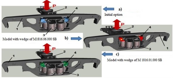
There are three options of test models:
- the first option with an initial design of the wedge-type shock absorber (see Fig. 5(a));
- the second option including a solid-state dynamic model of the wedge M 1816.01.000 SB (see Fig. 5(c));
- the third option including a solid-state dynamic model of the wedge M1816.06.000 SB of M 1819.00.000 SB (see Fig. 5(b)).
The dynamic model of the M 1816.01.000 SB wedge represents a system of rigid bodies possessing six degrees of freedom (vertical, case) 1 connected by linear power spring element 2 and rotary hinge 4. The movement of solid bodies relative to each other is limited by power contact elements 3 (limit the case turn relative to axis 4 clockwise within the existing gap) and 5 (limit the case turn relative to axis 4 clockwise).
The dynamic model of the wedge interacts with the truck bolster in the longitudinal and vertical directions by means of the power contact “point plane” elements entered on an auxiliary friction surface of the wedge and with the friction plate of the side frame entered on the main friction surface of the wedge [19-24].
The dynamic model of M1816.06.000 SB, M 1819.00.000 SB wedges represents a system of rigid bodies 1 possessing six degrees of freedom (case, insert) connected by linear power elastic and dissipative element 2. The movement of solid bodies relative to each other is limited by power contact elements 3 (insert movement limit along the axis of elastic element 2 towards case 1 within the existing gap of 4 mm) and 4 (limit the movement of insert 2 relative to case 1 in the directions perpendicular axes of elastic element 2). Since wear proof slip 3 (see Fig. 4) does not move relative to the case in the course of the wedge functioning, it is included in the dynamic model in the form of a uniform solid body with wedge case 1. The dynamic model of the wedge in the longitudinal and vertical directions interacts with the truck bolster by means of the power contact “point plane” elements entered on an auxiliary friction surface of the wedge (see Fig. 5(a)), and with the friction plate of the side frame entered on the main friction surface of the wedge (see Fig. 5(b)). In the cross direction, the wedge movement is limited within the allowable gaps by power contact elements between case 1 and the truck bolster, vertical 3 and the side frame of the truck. The general view of the M1816.06.000 SB, M 1819.00.000 SB wedge dynamic model is presented in, Fig. 5. The rigidity parameters of elastic elements of shock absorbers at the first stage are approximately defined proceeding from ensuring the needed friction force of absorbers both for an empty and loaded car. Determining the vertical rigidity of the wedge elastic element is performed for cars having the minimum container (21t – universal short-based platforms, for example, model 13-401). The needed value of the dry friction force of the frictional shock absorber is determined by the dependence specified in [13]:
where is the design amplitude of the periodical roughness of the rail way for the average way condition mm [10]; is the vertical rigidity of the truck suspension, kN/mm:
The needed friction force falling on one wedge-type shock absorber will make 3829 N (at the rate of 8 shock absorbers on a car). Proceeding from the design of the wedge-type shock absorber the friction force on the main friction surface between the wedge and the friction plate of the side frame in the descending and ascending movement of the truck bolster can be determined by the dependences specified in [16]:
where is rigidity of the springs supporting frictional wedges, accepted equal to 557 N/mm:
, are friction coefficients between the rubbing surfaces of the wedge main and auxiliary surfaces, are accepted to be equal to ;
is the inclining angle of the rubbing surfaces of the truck bolster and the frictional wedge (of the auxiliary surface), is accepted to be equal to 45°;
is the inclining angle of the rubbing surfaces of friction plates of the side frames and the frictional wedge (the main surface), is accepted to be equal to 2°;
deflection of the spring supporting the wedges is determined by the dependence:
where is deflection of the main springs of suspension, is accepted to be equal to :
The friction forces on the auxiliary friction surface between the wedge and the truck bolster at its descending and ascending movement are determined by the dependences [16]:
where , is the normal pressure on the wedge auxiliary surface at the descending and ascending movement of the truck bolster. The average friction force realized within a cycle of loading will make:
For the accepted initial data N, and the value of the missing friction force will make N. The ratios between the friction forces on the wedge auxiliary and main friction surfaces make:
The total friction forces provided by the wedge-type shock absorber are determined by the dependences:
Then the values of the missing on the auxiliary surface friction forces are determined by the dependences:
The additional efforts on the auxiliary friction surface will be determined by:
The elastic elements rigidity in the wedge is determined proceeding from the average normal pressure on the auxiliary surface:
The elastic element vertical rigidity that provides the needed friction force of the wedge-type shock absorber is determined by the dependence:
where is the element maximum static deflection, for three options of wedge-type shock absorbers are accepted to be equal to 4 mm. For assessing the operability of wedge-type shock absorbers option design, the obtained value of the elastic element rigidity is entered into dynamic models of wedges [25-27].
3. Results of computer modeling of eight-wheel freight car with modernized frictional wedges
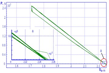
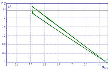
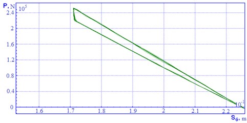
To evaluate the performance variants of embodiment wedge dampers, and the simulated force characteristics were obtained for hanging with wedges M 1816.01.000 SB, and the stiffness of the elastic element introduced into dynamic models of wedges taken 400 N/mm and 1300 N/mm to 2000 N/mm. For suspension with wedges M1816.06.000 SB, M 1819.00.000 SB rigidity of the elastic element introduced into the dynamic wedge model was assumed to be 1300 N/mm and 2800 N/mm (Figs. 6, 7).
Fig. 6Power characteristics for suspension with М 1816.01.000 SN wedges
a) Elastic element rigidity 400 N/mm
b) Elastic element rigidity 1300 N/mm
c) Elastic element rigidity 2000 N/mm
When modeling the operation of the proposed options of wedges in test models, the parameters of shock absorbers vary, and power characteristics of suspension as well as the efforts in contact power elements are defined for them. Power characteristics for suspension with M 1816.01.000 SB wedges are shown in, Fig. 6. On the abscissa axis, the coordinate of the truck bolster is put, on the ordinate axis, the efforts acting on the bar are put. The work analysis and the power characteristic of suspension with M 1816.01.000 SB wedges showed the following:
- the wedge design does not permit to increase the friction force on the auxiliary or main friction surface of due to changing the rigidity of the elastic element of the initial design, and it is only capable to compensate wear of the rubbing surfaces in use due to the case turning around the axis;
- with increasing the rigidity of then element more than 2000 N/mm, the wedge ability to compensate the arising wear due to excessive rigidity of the elastic element is broken [1, 2]. Power characteristics for suspension with M1816.06.000 SB, M1819.00.000 SB wedges are shown in, Fig. 7.
Fig. 7Power characteristics for suspension with М1816.06.000 SB, М 1819.00.000 SN wedges
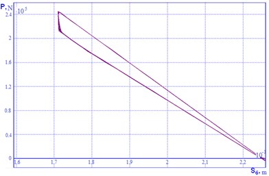
a) Elastic element rigidity 1300 N/mm
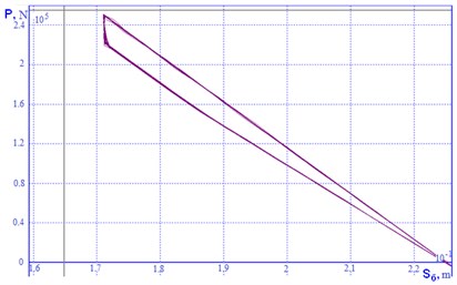
b) Elastic element rigidity 2800 N/mm
The work analysis and the power characteristic of suspension with M1816.06.000 SB, M1819.00.000 SB wedges showed as follows:
- the wedge design permits to change the friction force on the auxiliary and main friction surfaces due to changing the rigidity of the elastic element of the initial design;
- with decreasing the rigidity of the elastic element below 600 N/mm, insert 2 (see Fig. 7) rigidly rests constantly on the wedge case and the work of the shock absorber becomes completely similar to the work of the frictional shock absorber with a regular wedge;
- with significant increase in rigidity, more than 2800 N/mm, the decrease in contact stability of the main and auxiliary surfaces of the friction wedge is observed;
- the optimum operating mode of M1816.06.000 SB, M 1819.00.000 SB wedges corresponds to the elastic element rigidity within 800 – 1500 N/mm.
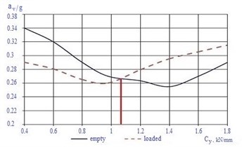
The assessment of the friction forces in the contact power element dependence on time showed that jamming and subsequent failure takes place in the place of interaction of the side surface of the insert to the wedge case [5]. Such work of the insert results in the instability of the wedge-type shock absorber work and emergence of additional revolting effects. The analysis of the absorber insert work showed that in the existing design within the provided gaps, there is an insert distortion that is confirmed by the trajectory of its movement obtained from the dynamic model [3, 4]. When increasing the gaps between the insert and the wedge case owing to wear, the distortion will increase that can lead to its full jamming. The body vertical accelerations dependences on the elastic element rigidity for М1816.01.000 SB wedge are presented in, Fig. 8.
Fig. 8Body vertical accelerations (in g shares) dependences on М 1816.01.000 SB wedge elastic element rigidity
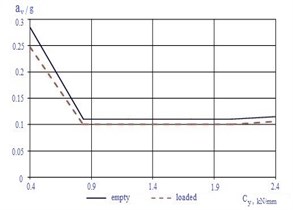
a) Speed 40 km/h
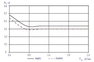
b) Speed 80 km/h
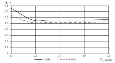
c) Speed 120 km/h
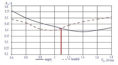
Fig. 9Dependences of body vertical accelerations on М1816.06.000 SB, М1819.00.000 SB wedges elastic element rigidity
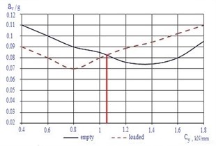
a) 40 km/h speed
b) 80 km/h speed
c) 120 km/h speed
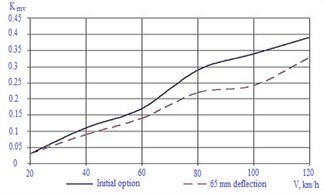
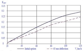
Fig. 10Dependences of changing coefficient of vertical dynamics on car movement mode
a) Empty on tangent track
b) Loaded on tangent track
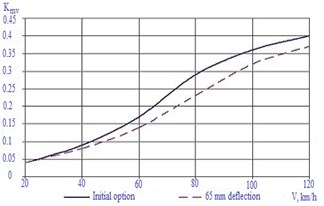
c) Empty on curved alignments
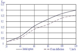
d) Loaded on curved alignments
Fig. 11Dependences of coefficient of horizontal dynamics on car movement speed
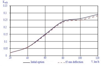
a) Empty on tangent track
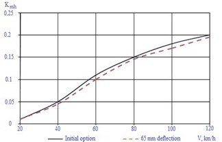
b) Loaded on tangent track
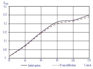
c) Empty on curved alignments
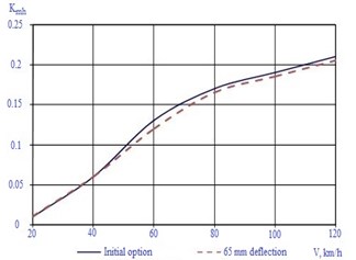
d) Loaded on curved alignments
The analysis of the obtained dependences, Figs. 8, 9. Permits to draw the following conclusions:
- decreasing rigidity of the elastic element of M 1816.01.000 SB wedge below 0.9 kN/mm leads to a significant growth in vertical accelerations both for empty and loaded cars;
- increasing rigidity of the elastic element of M 1816.01.000 SB wedge above 1 kN/mm does not practically effect vertical accelerations of loaded and empty cars, and they coincide with the accelerations obtained for the car with a regular wedge;
- the smallest vertical accelerations of the body in the truck central plate zone of an empty car arise with the rigidity of the elastic element of M1816.06.000 SB, M 1819.00.000 SB wedges equal to 1.4 kN/mm. The difference of the specified rigidity of that element from the one obtained by calculation is explained by that in the simplified calculations the friction forces between the insert and the case of the wedge were not considered;
- the smallest vertical accelerations of the body in the truck central plate zone of a loaded car arise with the rigidity of the elastic element of wedges of about 0.9 kN/mm, and with the rigidity of 1.4 kN/mm the increase of accelerations connected with the excess dry friction in the oscillatory system is observed.
Fig. 12Dependences of changing body vertical accelerations on car movement speed
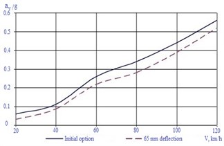
a) Empty on tangent track
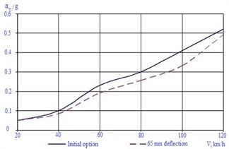
b) Loaded on tangent track
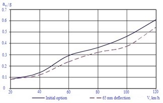
c) Empty on curved alignments
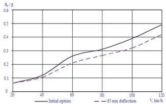
d) Loaded on curved alignments
Fig. 13Change of body horizontal accelerations on car movement speed
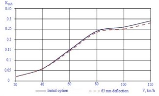
a) Empty car on tangent track
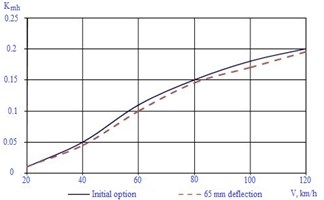
b) Loaded car on tangent track
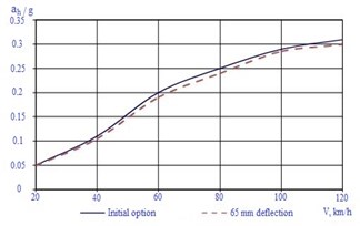
c) Empty on curved alignments
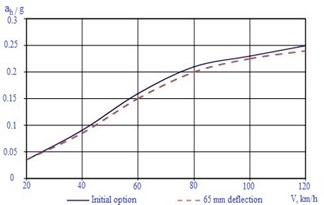
d) Loaded on curved alignments
4. Conclusions
Three options of modernization of wedge -type shock absorber of the cart of model 18-100 are studied in the present article for the purpose of compensation of wear surfaces in the operating process and providing a constant friction forces in wedge junctions with truck bolster and friction plate in the loaded and empty state. The offered wedge construction is interchanged with wedges applied now in cart of model 18-100. With the application of program complex for investigating the dynamics of rail crews “Universal machine” was executed modeling of dynamic characteristics of the freight car with the optimized parameters of friction shock absorber. The dynamic and block diagram of dynamic model of the car platform, and also mathematical model for developing friction force and interaction of contact power elements are worked out. The analysis of working capacity and the choice of rational parameters of options of modernization of wedge -type shock absorber of the cart of model 18-100 is executed on the basis of mathematical modeling of interaction of elements of wedges with truck bolster and friction plate of side frame with usage of the developed test models.
On the basis of the graphics analysis, presented in Fig. 10-13, it is possible to draw following conclusions about effect on the dynamic of the wagon of remodeled wedges M1816.06.000 SB, M 1819.00.000 SB:
- decrease of the coefficients of vertical dynamics approximately to 29 % is observed;
- vertical accelerations of the body in the truck central plate zone approximately to 18 % are decreased;
- coefficients of horizontal dynamics and horizontal accelerations of the body in the truck central plate zone are not practically changed.
Proceeding from the analysis of the construction of the offered options of wedges and dynamic characteristics of cars with trucks where they are mounted, it is possible to note the following shortcomings:
- to ensure the needed value of the dry friction of the car suspension in wedges, it is necessary to use elastic elements with the high rigidity of 1100 N/mm;
- the offered options of wedges do not permit to improve cross dynamics of the car.
For eliminating specified shortcomings, it is expedient at modernizing the truck in the central core stage to provide additional devices, for example, friction shock absorber in the central step of suspension.
References
-
Pogorelov D. Yu Introduction to modeling of the systems dynamics of freight cars. Bryansk BSTU, 1996, p. 150-156.
-
Houthis V. D., Anisimov P. S. Power characteristics of frictional wedge-type shock absorbers in mathematical models of studying freight cars. VNIIZhT Bulletin, Vol. 4, 2005, p. 127-133.
-
Inozemtsev V. G., Husidov V. D., Khokhlov A. A., Petrov G. I. Dynamics of freight car, ways of decreasing wheels wear and preventing descents. Transport, 2013, p. 130-137.
-
Vershinsky S. V., Danilov V. N., Husidov V. D. Car Dynamics: Textbook for Higher Education Institutions. 3rd Revision, Transport, 1991, p. 351-360.
-
Kure G. Design roughness of railway track for use when studying and designing passenger and freight cars. 2nd International Conference on Railway Bogies, Budapest, 1992, p. 68-96.
-
Muginstein L. A., Lisitsyn A. L. Non-Stationary Modes of Draught (Coupling. Critical Norm of Train Mass). Intext, 1996, p. 169-176.
-
Pogorelov D. Yu Computer dynamics modeling of rail cars. Mechanics and Tribology of Transport Systems. 2003, p. 226-232.
-
Lukin V. V., Shadur L. A., Koturanov V. N., Khokhlov A. H., Anisimov P. S. Design and Calculation of Cars. Textbook for Higher Education Institutions of Railway Transport. Russia, 2000, p. 726-731.
-
Tretyakov A. V. Management of Individual Resource of Cars in Operation. Ph.D. Thesis, St. Petersburg, 2004, p. 25-32.
-
Zakalo V. I., Kosov V. S. Contact problems of railway transport. Mechanical Engineering, 2004, p. 488-496.
-
Koturanov V. N. Bases of designing and examining technical solutions. Tutorial, Marshnut, 2005, p. 482-490.
-
Orlova A. M., Boronenko Yu P. Synthesis of saved-up design experience of trucks of freight cars for creation of standard series. Problems of Mechanics of Railway Transport, Dnepropetrovsk, 2004, p. 45-53.
-
Orlova A. M., Vasilyev S. G., Rudakova E. A. Comparison of dynamic loading of side frame of truck of freight car at existence and lack of axlebox shock-absorber. Rolling Stock of the XXI Century: Ideas, Requirements, Projects, 2003, p. 124-136.
-
Galichev A. G. Influence of Tribotechnical Condition of Wheels and Rails on Movement Dynamics of Cargo Locomotive in Rundown and Draft Modes. Ph.D. Thesis, Bryansk State, 2002, p. 22-33.
-
Pranov A. A., Yefimov V. P. Modernization of truck of model 18-100 – effective way of increase of traffic safety of trains. Heavy Mechanical Engineering, Vol. 12, 2003, p. 124-132.
-
Yefimov V. P., Pranov A. A. Development and carrying out of complex of tests of truck of model 18-578. Problems of Mechanics of Railway Transport, Dnepropetrovsk, 2004, p. 98-105.
-
Orlova A. M., Boronenko Yu P. Synthesis of saved-up experience of designing trucks of freight cars for developing a typical dimension series. Problems of Mechanics of Railway Transport, 2004, p. 45-55.
-
Orlova A. M., Vasilyev S. G., Rudakova E. A. Comparison of dynamic loading of side frame of truck of freight car in existence and absence of axle-box shock-absorber. Rolling Stock of the XXI Century, Ideas, Requirements, Projects, 2003, p. 456-461.
-
Galichev A. G. Influence of Tribotechnical Condition of Wheels and Rails on Dynamics of Movement of Freight Locomotive. Ph.D. Thesis, Bryansk State, 2002, p. 34-42.
-
Pranov A. A., Yefimov V. P. Modernization of truck of model 18-100 as effective way of increasing traffic safety of trains. Heavy Mechanical Engineering, Vol. 12, 2003, p. 75-85.
-
Yefimov V. P., Pranov A. A. Development and carrying out of complex testing of truck of model 18-578. Problems of Mechanics of Railway Transport, Dnepropetrovsk, 2004, p. 123-135.
-
Nikiforov N. I., Zagorsk M. V., Simonov V. A. Studying the influence of parameters of the mechanism of radial mounting of wheel pairs on running dynamics of locomotive. Transport, Vol. 6, Issue 52, 2002, p. 65-69.
-
Samuels J., Potassium C. Improvement of interaction of rolling stock and way. Railroads of the World. Vol. 2, 2003, p. 18-24.
-
Simonov V. A., Kovalyov R. V., Kotov S. V., Yefimov V. P. Influence of parameters on axle-box adapters for 18-100 type truck on indicators of wear of wheel pairs bandages and stability of movement of freight cars. BSTU Bulletin, Vol. 1, Issue 1, 2004, p. 147-155.
-
Kossov V. S. Proc. of VNIKTI on developing of three-element truck for freight cars with axial load 245 kN. Problems of Mechanics of Railway Transport. Dnepropetrovsk, 2004, p. 45-65.
-
Yazykov V. N. Application of Model of Non-Hertz Contact of Wheel with Rail for Assessing Dynamic Qualities and Indicators of Wear of Wheels of Cargo Locomotive. Ph.D. Thesis, Bryansk State Technical University, Bryansk, 2004, p. 68-74.
-
Buzalo G. A. Mathematical Modeling of Dynamic Processes at Passive and Operated Passage by Engine of Curvilinear Parts of Way. Ph.D. Thesis, Rostov-on-Don, 2003, p. 18-27.
Cited by
About this article
Co-authors brought the following contributions for the development of the paper. Prof. Solonenko V. developed the theoretical basics of freight cars. Prof. Mahmetova N. developed the kinematic scheme for the freight car for wedge-type shock absorber. Dr. Zhauyt A. made mathematical model and numerical check of the system. Prof. Musayev J. analyzed and calculated the parameters for the virtual model of the freight car. Ass. Prof. Kuashnin M. developed the virtual model of the proposed freight car within UM software. Simulation and numerical check of the virtual model have been done by ass. Prof Kuashnin M. and Buzauova T.
