Abstract
This paper presents a new method which focuses on the multi-axis fatigue loading mode for wind turbine blade and aims to shorten the fatigue loading cycle. The whole test scheme is design for the measurement of fatigue loading system. The two leading sources of fatigue loading system are asymmetric arrangement in the space. In addition, its vibration mathematical model is derived according to the Lagrange equation. The numerical simulation model is developed by means of Matlab Simulink. The vibration coupling characteristics including motor revolution speed, phase and amplitude of wind turbine blade is obtained. Moreover, the trajectory of wind turbine blade is obtained. Finally, a multi-axis fatigue loading platform for small wind turbine blade is built for the proposed study. The on-site test showed that if the revolution speeds of the two loading sources is the same as the natural frequency of wind turbine blade, the revolution speed, the phase angle of motor and the blade trajectory were relative changed smoothly. Thus, the amplitude of blade is state and the largest. Otherwise when the revolution speed of motor is different with the natural frequency of blade, the revolution speeds and phase angle of the two loading sources fluctuated largely. The above conclusion provided the theoretical basis for the subsequent decoupling control algorithm of multi-axis fatigue loading test.
1. Introduction
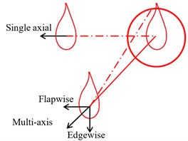
Among all renewable energies, the wind energy has shown very broad applications. The main component of wind turbine is wind turbine blade. Its main failure mode is fatigue damage because of the alternate loading. Thus, the fatigue loading test is an effective method to check the anti-fatigue property for wind turbine blade [1-3]. Generally, fatigue loading test apply to the single-axis excitation mode at home and abroad, and there are two problems in this loading mode. Firstly, the flap wise and edgewise direction of blade needs to do fatigue loading test respectively. But the measurement is lengthy and time consuming. Secondly, according to the statistical report of National Renewable Energy Laboratory, the phase angle between the two loading direction of blade is approximately present Gauss distribution. Moreover, the probability of phase angle is 72 degrees, because of the variation of the wind direction (shown in Fig. 1). The actual force of blade should be the synthetic force of two direction loading (shown in Fig. 2). So the single-axis loading mode is inappropriate in real application. This could lead to the inaccuracy of the test result. Based on the above discussion, this paper proposed a new multi-axis fatigue loading method driven by electric mass in order to get the accurate measurement results of wind turbine blade. In this loading method, the space structure of two loading sources is in asymmetric condition. An electromechanical coupling system has been form between them and the blade. Thus, the proposed vibration characteristics of multi-axis loading system has the good theoretical significance for the subsequent fatigue test. There were a lot of researches with the two loading sources vibration field already have done. Massicotte et al. obtained the theoretical conditions for the vibration self-synchronization of the loading system according to the mathematical model of vibration coupling and at the same time analyzed the variation laws by using simulation model [5-7]. As for the stability of multi-excitation vibration, De-gang Wang analyzed the dynamic vibration characteristics of the multi-excitation system quantitatively through establishing its accurate dynamic model [8]. Tian-xia Zhang applied the nonlinear method to establish the model of the loading system driven by the eccentric mass. Its mathematical description of structural parameters was given, and the variable range of vibration parameters was determined [9]. The above results indicated that vibration coupling between the two loading sources is inherent. The research method also provided a good reference value for the vibration characteristics of wind turbine blade with multi-axis loading system.
Fig. 1Distribution curve of phase angle
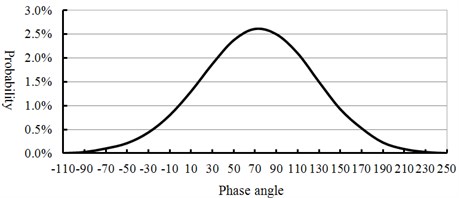
Fig. 2Actual loading direction of wind turbine blade
2. Design of fatigue loading system
2.1. Multi-axis loading scheme
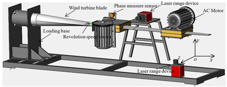
The multi-axis fatigue loading system (Fig. 3) mainly included loading base, wind turbine blade and two fatigue loading sources. The two loading sources were connected with the wind turbine blade by wood saddle. The loading base was fixed on the ground, and the blade root was fixed on the loading base through a high strength bolts. Loading source was composed of AC motor, a reducer, a connecting clamp and a control cabinet. Two laser range devices were used to measure the amplitude of two loading direction, and the two pulse sensor were used to measure the revolution speed of loading source.
Fig. 3Multi-axis fatigue loading scheme of wind turbine blade
2.2. Measurement of speed difference, phase difference and amplitude
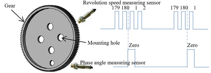
High counting sensor which adopting advanced detection technology could identify every teeth of gear and convert it into a square wave output. Output shaft of each loading source installed with a measuring gear and two sensors measuring the revolution speed and phase angle, as shown in Fig. 4. The speed measuring gear had 180 teeth and each of which represented two angles. There was a zero mark on the speed measuring gear. During the measuring, each gear speed sensor produced a pulse when a tooth of gear was detected, so the driving speeds and phases of the unbalanced shafts could be obtained. A proximity switch is installed below every unbalanced shaft to realize the reset of phase.
Fig. 4Speed difference and phase difference detection scheme
The centrifugal force generated by each eccentric mass was defined as the center of gravity line (denoted by M1 and M2). The two center line of gravity could be maintained at a constant angle, which indicated that the two loading source vibrated synchronization. Take the two loading sources for example, the revolution speed difference Δv(t) (rad/s) and phase angle difference Δφ(t) (rad) could be expressed as:
where: v1(t), v2(t) – revolution speed of eccentric mass; M1(t), M2(t) – the position of eccentric mass; Δφ(t) – phase angle difference; ΔM(0) – initial position.
The differential detection of revolution speed and phase angle could be realized according to Eqs. (1)-(3).
Non-contact laser measurement was used to avoid damage for the measuring equipment because of the blade vibration. Measurement equipment was laser range device. The laser range mode was set a one-way transmission mode and communication format was set to: 19200.EVEN.8.1. Data transmission cycle was T=30 ms. The blade amplitude was represented by three bytes. The commutation protocol was shown in Table 1.
Table 1Laser ranging protocol
7bit | 6bit | 5bit | 4bit | 3bit | 2bit | 1bit | 0bit |
Data (L) | 0 | 0 | |||||
7bit | 6bit | 5bit | 4bit | 3bit | 2bit | 1bit | 0bit |
Data (M) | 0 | 1 | |||||
7bit | 6bit | 5bit | 4bit | 3bit | 2bit | 1bit | 0bit |
× | × | Data (H) | 1 | 0 | |||
According to the communication protocol of Table 1, the formula of blade amplitude was calculated as follows: Amplitude = (L≫2)+(M≫2)*64+((H≫2)&0×0F)*4096;
3. Electromechanical coupling dynamic model
3.1. Mathematical model
According to the multi-axis loading scheme of wind turbine as shown in Fig. 3, some assumptions were made as the following:
(1) The blade was flexible, and the loading source was rigidly connected to the blade.
(2) When the blade vibrates, damping force and elastic force were proportional to the velocity and displacement of the blade respectively.
(3) xoy plane was in the blade oriented direction, and xoz plane was in the blade tangential direction.
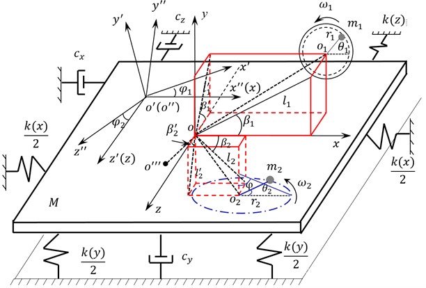
Three coordinate systems and five degree freedoms were defined: translatory motion along the x axis, y axis, z axis and rotation around the x axis, z axis respectively. The proposed Dynamic model as shown in Fig. 5.
As shown in Fig. 5, oxyz was the absolute coordinate system, o'x'y'z' and o''x''y''z'' were the moving coordinate systems, o'(o'') was motion synthesis centroid of the system; o''' was the centroid of the whole vibration system (including the blade and the two loading sources). In addition, M was the equivalent weight of the blade; o1 and o2 were the rotary center of two eccentric mass respectively. And, l1and l'1 were the projection of oo1 in the plane xoy and yoz respectively; l2 and l'2 were the projection of oo2 in the plane xoy and yoz respectively. The angle between l1, l2 were β1 and β2and the positive direction of x-axis respectively. β'1 was the angle between l'1 and the negative direction of z-axis and β'2 was the angle between l'2 and the positive direction of z-axis; mi(i=1, 2) was the equivalent weight of the eccentric mass; ri(i=1, 2) was the equivalent eccentricity of the eccentric mass; θ1 and θ2were the rotation angle of the eccentric mass respectively, and ωi=dθi/dt (i=1, 2); φ was the rise angle of connecting rod m2.
The kinetic energy T of the proposed system was expressed as:
+12∑2i=1Ji˙φ2i+12m1[(˙x-˙φ1l1sinβ1+˙θ1r1cosθ1)2+(˙y+˙φ1l1cosβ1+˙φ2l'1cosβ'1
+˙θ1r1sinθ1)2+(˙z+˙φ2l'1sinβ'1)2]+12m2[(˙x+˙φ1l2sinβ2-˙θ2r2sinθ2)2
+(˙y+˙φ1l2cosβ2+˙φ2l'2cosβ'2)2+(˙z+˙φ2l'2sinβ'2-˙θ2r2cosθ2)2]+12∑2i=1J'i˙θ2i,
where, Ji(i=1, 2) is the equivalent moment of inertia of the whole system; J'i (i=1, 2) is the equivalent moment of inertia of the eccentric mass.
The potential energy V of the system was expressed as:
where, k(x), k(y), k(z), kφ1, kφ2 are the equivalent stiffness of these directions.
The kinetic energy T and potential energy satisfied the following equation according to the Lagrange equation:
External force of the system Q was expressed as:
where, cx, cy, cz, cφi(i=1, 2) are the equivalent damping of vibration direction; ci(i=1, 2) is the equivalent damping of motor output shaft and, Tmi, Tfi (i=1, 2) are the electromagnetic torque and load torque of motor.
x, y, z, φi, θi (i=1, 2) were regarded as generalized coordinates. Then include the kinetic energy, potential energy and the energy dissipation function of the whole system into the Lagrange equation, and the dynamic equation of the multi-axis fatigue loading system was established as follows:
3.2. Mathematical model of AC motor
Three-phase asynchronous motor provided power for the loading sources, and its state equation under the two-phase synchronous rotating coordinate system could be represented as Eq. (9) [10-11]:
×1L2m-LsLr[IdsIqsIdrIqr]+[Lr0-Lm00-Lr0LmLm0-Ls00Lm0-Ls][UdsUqsUdrUqr]˙ωr
where, Uds, Uqs, Udr, Uqr – stator terminal voltage, rotor terminal voltage under two-phase synchronous rotating coordinate system; Ids, Iqs, Idr, Iqr – stator terminal current, rotor terminal current under two-phase synchronous rotating coordinate system; Rs, Rr, Ls, Lr, Lm – stator, rotor resistance, self- inductance and mutual inductance; ω1, ωr – synchronous rotating angular velocity and the angular velocity of rotor; D, TL, np, Jm – coefficient of resistance moment, the load torque of the motor, pole pairs and inertia moment; id1, id2 – component of stator current under d shafting; Iq1, Iq2 – Component of stator current under q shafting.
Fig. 5Dynamic model of multi-axial loading mode
3.3. Simulation model
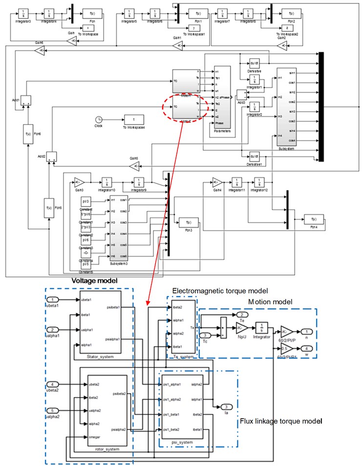
It was difficult to get the exact solution of mathematical model from above equations because of the multi variable electromechanical coupling effect. In order to get the vibration characteristics of multi-axis fatigue loading system visually, simulation model based on Matlab/Simulink software was established according to mathematical model. It was showed in Fig. 6. Motor A and Motor B were two loading sources. Every simulation model of AC motor included voltage model, electromagnetic torque model, motion model and flux linkage torque model.
3.4. Analysis of simulation test
The simulation model parameters were set as: M=25 kg, m1=m2=2 kg, r1=0.15 m, r2=0.15 m, l1=0.05 m, l2=0.25 m, l'1=0.06 m, l'2=0.16 m, β1=β2=14°, β'1= 42°, β'2=48°. The initial phase angle of two loading sources was zero. The initial setting revolution speeds of the loading source were n1=50 r/min and n2=55 r/min in flapwise direction. The initial setting revolution speeds of the loading source were n3=70 r/min and n4=75 r/min in edgewise direction. n1=50 r/min and n3=70 r/min were the same as the nature frequency of blade in flapwise and edgewise direction respectively. The revolution speed and phase angle variable simulation results of the loading source were shown in Fig. 7 and Fig. 8. The amplitude of wind turbine blade and the overall trajectories of the flapwise direction were shown in Fig. 9.
Fig. 6The simulation model of multi-axis excitation system
The above simulation results showed that when the excitation frequency of the two loading source was same to the natural frequency of the blade vibration direction, the revolution speed of two loading sources of loading tend to be stable as shown in Fig. 7(a) and Fig. 8(a). The phase angle variation in two directions was relatively stable, as shown in Fig. 7(c) and Fig. 8(c). The vibration trajectory, not only the flapwise direction but also two directions, could get a stable large amplitude relatively, as shown in Fig. 9(a) and Fig. 9(c). When the excitation frequency of two loading source were differ to a large extent with the nature frequency of blade respectively, the revolution speeds of two loading sources were difficult to achieve vibration synchronous due to the inherent electromechanical coupling effect as shown in Fig. 7(b) and Fig. 8(b). The phase angle variation and the overall trajectory of wind turbine were disorder as shown in Fig. 7(c), Fig. 8(c), Fig. 9(b) and Fig. 9(d).
Fig. 7Revolution speed and phase angle simulation of loading source in flapwise direction
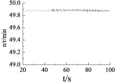
a)n1=50 r/min, revolution speed of loading source
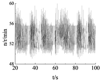
b)n2= 55 r/min, revolution speed of loading source
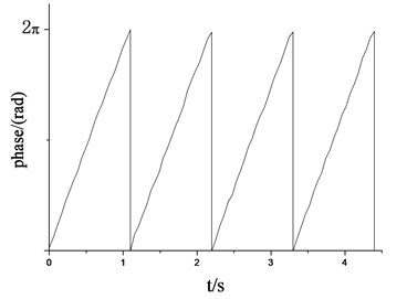
c)n1=50 r/min, phase angle of loading source
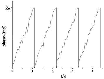
d)n2=55 r/min, phase angle of loading source
Fig. 8Revolution speed and phase angle simulation of loading source in edgewise direction
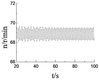
a)n3=70 r/min, revolution speed of loading source
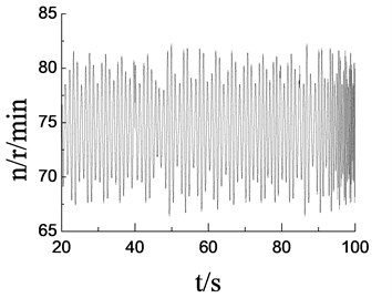
b)n4=75 r/min, revolution speed of loading source
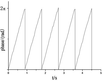
c)n3= 70 r/min, phase angle of loading source
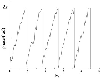
d)n4=75 r/min, phase angle of loading source
Fig. 9Vibration trajectory simulation of wind turbine blade
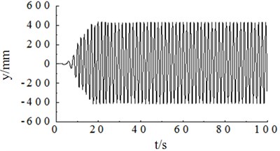
a)n1=50 r/min, amplitude simulation curve of flapwise direction
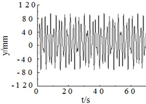
b)n2=55 r/min, amplitude simulation curve of flapwise direction
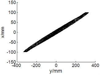
c)n1=50 r/min, n3=70 r/min, vibration trajectory of blade
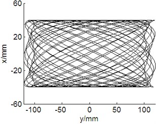
d)n2=55 r/min, n4= 75 r/min, vibration trajectory of blade
4. Test verification
4.1. Experiment platform
In order to verify the theoretical analysis and the simulation results, a multi-axis fatigue loading test system of small wind turbine blade was set up. The HMI monitoring interface based on Labview software was developed as shown in Fig. 10.
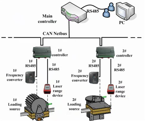
The whole control system used the distributed network bus mode, which was shown in Fig. 11. Two slave controllers controlling the frequency converter adjusted the revolution speed of every loading source. Laser range devices, measuring the amplitude of the blade through the RS485 bus, transmitted data to the controller. The main controller and the slave controllers exchanged the data through the CAN bus. The main controller and the monitoring interface also used the RS485 bus to realize the data exchange. All useful information was displayed and saved on the monitor interface.
Fig. 10Test platform and interface monitor
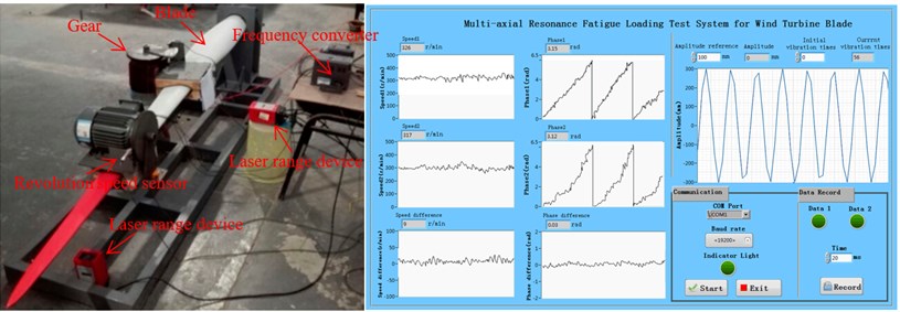
Fig. 11Distributed network control architecture
Infinon XC164CS MCU was used for control the system hardware. The software in Keil3.0 compiler environment used C language to complete. The measure device for revolution speed was used the high-speed counting sensor and gear. Test parameters were shown in Table 2.
Table 2Test parameters
Parameters | Value |
Blade length (m) | 2.3 |
Blade weight (kg) 1st frequency in flapwise (Hz) 1st frequency in edgewise (Hz) | 25 0.86 1.15 |
Eccentric mass (kg) | 2 |
Eccentric length (m) | 0.15 |
Motor power (kW) Frequency converter Laser range device Sensor type | 0.75 ABB ADSL-30 CORON-CTS |
Test temperature (°C) | 23 |
Humidity(RH) | 36 % |
4.2. Test result and analysis
When the revolution speed of the loading source was respective setting with 50 r/min and 55 r/min in flapwise direction, the revolution speed and phase angle variation of loading source were measured as shown in Fig. 12. According to the test results, when the setting revolution speed was same to the natural frequency of blade (n=50 r/min), revolution speed of loading source tends to be stable, and the phase angle varied smoothly. When the setting revolution speed was different with the natural frequency of blade (n=55 r/min), due to the coupling effect between them, the revolution speed and phase angle variation of loading source fluctuated significantly. Above test measure results were basically match with the simulation results.
When the revolution speed of the loading source was also respective setting 70 r/min and 75 r/min in edgewise direction, the revolution speed of loading source was measured as shown in Fig. 13. According to the test results, when the setting revolution speed was same with the natural frequency of blade (n=70 r/min), revolution speed of loading source tends to be stable and the phase angle varied smoothly. When the setting revolution speed was different with the natural frequency of blade (n=75 r/min), due to the coupling effect between them, the revolution speed and phase angle variation of loading source also fluctuated significantly. Above test measure results were also basically match with the simulation results.
Fig. 12Revolution speed and phase angle test curve of loading source in flapwise direction
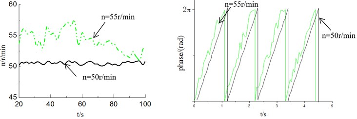
Fig. 13Revolution speed and phase angle test curve of loading source in edgewise direction
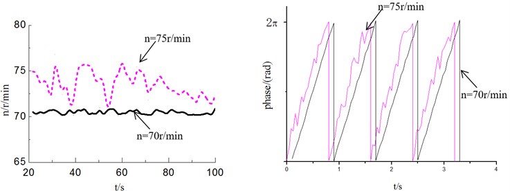
Fig. 14Vibration trajectory test curve of wind turbine blade
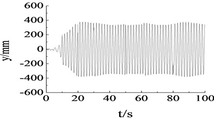
a) Amplitude test curve of flapwise direction in resonance
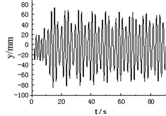
b) Amplitude test curve of flapwise direction in non-resonance
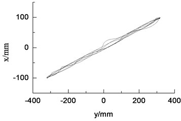
c) Vibration trajectory in resonance condition
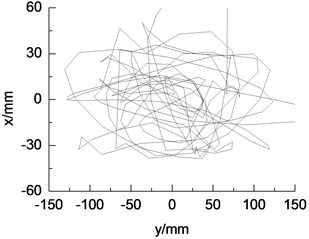
d) Vibration trajectory in non-resonance condition
When the revolution speed of loading source matched with the natural frequency of wind turbine blade, amplitude of blade was not only stable, but also maximum, about 400 mm. The vibration trajectory was stable. Such condition was suitable for multi-axis fatigue loading test. When the setting revolution speed of the loading source was different with the natural frequency of the blade, the amplitude and vibration trajectory of the blade were in disorder because of the electromechanical coupling effect, as shown in Fig. 14.
5. Conclusions
In this paper, a new multi-axis fatigue loading system of wind turbine blade driven by electric mass was designed. The measurement method for revolution speed, phase angle of loading source and blade amplitude was given. The conclusions were obtained in follows.
1) In order to shorten the measuring time for wind turbine blade fatigue loading test, the multi-axis fatigue loading system based on electric mass driven was designed. By establishing the mathematical model for multi-axis fatigue loading system according to the Lagrange equation, it was found that the proposed system was an electromechanical coupling system. Its numerical solution was very difficult to get.
2) The vibration characteristics of multi-axis fatigue loading system were visually obtained through the numerical simulation model. When the revolution speeds of two loading source were same to the natural frequency of the blade vibration direction, the revolution speed and phase angle variation of loading source were basically stable. Moreover, the vibration trajectory was relatively smooth. The amplitude of blade was maximum, which was suitable for fatigue loading test. When the revolution speeds of loading source were different with natural frequency of wind turbine blade, the revolution speed and phase angle of loading source fluctuated significantly and vibration trajectory was rough. In order to obtain the better measurement effect, the corresponding decoupling control algorithm was needed in future.
3) A multi-axis fatigue loading experiment platform was developed. Using this test platform, the test result was basically same with the simulation result, which verified the accuracy of the mathematical model and simulation model in this paper. All the above findings have theoretical and engineering significance for the structure redesign of wind turbine blade
References
-
Liu Deshun, Dai Juchuan, Hu Yanping, et al. Status and development trends of modern large-scale wind turbines. China Mechanical Engineering, Vol. 24, Issue 1, 2013, p. 125-135.
-
Kong C., Bang J., Sugiyama Y. Structural investigation of composite wind turbine blade considering various load cases and fatigue life. Energy, Vol. 30, 2005, p. 2101-2114.
-
Huang Xuemei, Zhang Leian, Yuan Guangming, et al. Accuracy improvement on fatigue test of megawatt wind turbine blades by adaptive fuzzy control. Journal of Vibroengineering, Vol. 16, Issue 6, 2014, p. 2631-2638.
-
White D., Musial W., Engberg S. Evaluation of the new B-REX fatigue testing system for multi-megawatt wind turbine blades. 43rd AIAA Aerospace Sciences Meeting and Exhibit, USA, Vol. 6, 2005, p. 10-13.
-
Massicotte D., Megner B. Neural-network based method of correction in a nonlinear dynamic measuring system. IEEE Transaction on Instrumentation and Measurement, Vol. 39, Issue 4, 1999, p. 1641-1645.
-
Suykens J. A. K. Nonlinear modeling and support vector machines. IEEE Instrumentation and Measurement Technology Conference, Budapest, 2001, p. 287-294.
-
Xiao Chen, Wei Zhao, Xiao Lu Zhao, et al. Failure test and finite element simulation of a large wind turbine composite blade under static loading. Energy, Vol. 7, 2014, p. 2274-2297.
-
Wang Degang, Yao Hongliang, Feng Fei, et al. Dynamic coupling feature and experimental study of self-synchronous vibrating system. Journal of Vibration, Measurement Diagnosis, Vol. 32, Issue S2, 2012, p. 53-58.
-
Zhang Tianxia, Xiaoyu E., Wen Bangchun Coupling effect in a synchronous vibration system. Journal of Northeastern University, Vol. 24, Issue 9, 2003, p. 839-842.
-
Zhang Nan, Hou Xiaolin, Wen Bangchun Synchronous theory for multi-type self-synchronous vibration systems. China Mechanical Engineering, Vol. 30, Issue 15, 2009, p. 1838-1844.
-
Lai Xin, Wu Jianzhong, Zhou Wen, et al. Synchronization control and electromechanical coupling characteristics of pile hammer synchronous vibration system. Journal of Tongji University, Vol. 48, Issue 6, 2012, p. 920-925.
Cited by
About this article
This work was sponsored by National Natural Science Foundation of China (No. 51405275 and No. 51305243) and Shandong Provincial Natural Science Foundation (No. ZR2014EL027) and China Postdoctoral Science Foundation (2015M571840).

