Abstract
Using DEFORM-3D with the single channel brass H63 channel Angle extrusion deformation of computer simulation, such as extrusion process for the change of load, velocity of billet, the effective stress and the distribution of strain rate, grain size billets are analyzed, and the results show that the friction force had a great influence on extrusion process of load, the change of effective stress and strain rate trend, along with the change of extrusion for grain size refinement in a certain extent, but the different location of grain size and distribution is uneven. For the ECAP (equal channel presents pressing) grain refining process of industrial production and application to provide certain theoretical basis.
1. Introduction
As everyone knows, have close relation to many properties and grain size of metal materials, according to Hall-Petch formula σs=σ0+Kd-1/2 [1] shows that the average grain diameter is small, deformation resistance, tensile strength and hardness properties of metals will be greatly improved; at the same time, the grain size is small, better plastic, toughness index is also higher. Therefore, the grain size is an effective way to improve the performance of metal materials, and the traditional pressure processing technology (such as rolling, extrusion, drawing, etc.) can refine the grain size [2], but the shape and size of the billet is often limited. ECAP method in the large plastic deformation method has been studied since twentieth Century. ECAP method is a kind of advanced technology, which is based on the theory of large plastic deformation (SPD), which is a kind of advanced technology, which has been studied by many scholars because of its special advantages. At present, Al, Mg, Cu, Ti and the structure of the alloy have been successfully prepared by this technique [3]. In this paper, H63 (CuZn37) brass rod as the research object, and the process of ECAP is studied from the perspective of DEFORM-3D finite element simulation. The change of load and the influence of friction on the extrusion load, the variation of material flow velocity, the variation of the strain rate and the distribution of grain size are studied.
2. Single pass ECAP method forming finite element modeling
2.1. The principle of ECAP
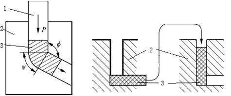
The principle of ECAP method is: the use of two intersecting equal channel to form the extrusion die, so that the extrusion of the metal to obtain a larger plastic shear deformation, the principle of which is shown in Fig. 1. ECAP could consists of two equal cross section areas, crossed and fully connected channel, two channels in the inner corners of the mold cross Ø, the external arc angle is ψ. In the ECAP deformation process, the specimen and the die channel closely and mold wall lubrication is good, the specimen in the top die under the action of vertical channel from the upper press, then from the right end of the horizontal channel extrusion, when using a two channel corner, pure shear specimen subjected to approximate ideal deformation. In each specimen before and after extrusion, cross-sectional area and cross-sectional shape almost does not change, so it can be repeated so that the extrusion pass deformation strain accumulated, so as to obtain the total strain is quite large, until get the required strong plastic deformation, and obtain good effects on grain refinement, the significant changes in physical properties and mechanical properties of materials.
Fig. 1Process routes of the schematic diagram of the ECAP method and way: 1. Top die, 2. Bottom die, 3. Billet
2.2. The basic equation of rigid-plastic finite element method
In the ECAP, the billet is gradually entered into the corner when the die is squeezed, the stress state in elastic deformation stage first, and then in a plastic deformation stage, and the constitutive equations of these two phases are different [5]. For the problem with most of the bulk metal forming, plastic deformation process elastic deformation relative plastic deformation is very small, negligible, so you can simplify the rigid-plastic material [6]. The volume of the deformation body is V, the deformation force is Pi, the surface area is S, on the S force face St given surface force qi, on the S speed surface Sv given speed Voi. The material in the flow process to meet the basic equations of the mechanical:
1) The stress equilibrium equation (equations of motion):
2) The strain rate, velocity relationship equation (geometric equation, deformation coordination equations):
3) Levy-Mises stress-strain rate relationship equation:
Above the formula, ˙ˉε=√23˙εij˙εij is equivalent strain rate, ˉσ=√32σ'ijσ'ij is equivalent stress.
4) Yield rule. Using Mises yield rule and isotropic hardening model, the initial yield rule:
Subsequent yield conditions, for static loading only consider the strain hardening can be obtained:
H can be determined by one-way tensile test curve.
For sticky plastic material, load should also consider the time factor that is affecting the speed of deformation, instantaneous yield conditions:
Y can be determined by a one-dimensional dynamic test.
5) Constant volume conditions:
6) Boundary conditions. Boundary conditions on the St:
The speed of the boundary conditions on the Sv:
The field variables in the plastic forming process can be solved by using the above equation and boundary conditions, but in fact it is only in a few simple cases that can be obtained. For most of the situation, it is often necessary to simplify the actual problem, using traditional analytical methods such as principal stress method, slip line method and so on, and the results are often different from the actual situation. The finite element method is used to discrete the deformation body, with the aid of the principle of virtual work or the variational method, we can get the satisfied results of the practical engineering.
2.3. Establish solid model
Billet is rectangular, cross-sectional dimensions of 12 mm×6 mm, length 80 mm, split mold including the bottom die, the top die and the sleeve, the bottom die channel interior angle Ø = 100°, exterior angle ψ= 45°. Using Pro/E software to establish a physical model, DEFORM-3D software in the assembly model shown in Fig. 2.
Fig. 2Assembly diagram before and after
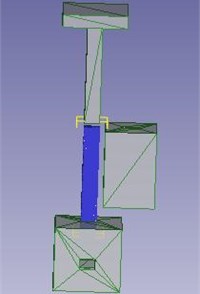
a)
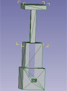
b)
2.4. Selection of process parameters
Billet material CuZn37, mold set rigid, Billet set rigid-plastic. The top die during the forming process at a constant speed along the Z-axis negative direction, the die and the stationary sleeve. Specific process parameters are shown in Table 1.
3. Simulation results and analysis
Through the analysis and calculation, the change of extrusion load, flow field, stress strain field, grain size and distribution are obtained.
Fig. 3The load of the extrusion process
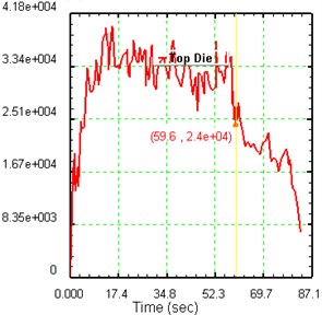
Table 1Process parameters
Process parameter name | Process parameter values |
Poisson’s ratio | 0.35 |
Elastic modulus (MPa) | 9.1e+4 |
Mesh nodes | 5845 |
Mesh number | 24337 |
Friction coefficient | 0.08/0.12 |
Top die velocity (mm/s) | 1 |
Simulation steps | 80 |
3.1. Analysis of the extrusion load
Time load curve shown in Fig. 3, the beginning of a sharp increase in the load, suggesting that Billet has been entered into the corner of the die channels, Billet Z-axis direction component die a sudden action and generating frictional contact with the channel wall, so the load rise very quickly. When 12.8 s maximum of 3.95e+4 N. Then gradually decreases, extruded into a relatively stable state, the load curve fluctuates with time up and down, fluctuating curves reason is: because contact with the channel wall Billet and die, causing a change in friction.
When the extrusion process proceeds to 58.1s, the load is 3.49e+4 N, adjust the friction coefficient, from 0.12 to 0.08, down from Fig. 3 that the load to the 2.74e+4 N, then easing the load decreased. To the 79 s, the last point of the billet is extruded to the corner, and the load of the top die is also reduced. Therefore, in the actual extrusion process, sufficient lubrication of the die channel, can greatly minimize extrusion load, effectively reduce energy consumption, and improve the life of the mold.
3.2. Analysis of material flow field
Velocity is an important parameter in the process of equal channel angular pressing. The size and uniformity of the loading speed of the top die not only directly affect the load of the top die and die, but also affect the quality of the products. Studies have shown that: the degree of uniformity of the flow velocity of the material as possible, smaller defects factor profiles, flat profiles more [4].
As shown in Fig. 4, in the middle of the billet pick a track point 1, the bottom of the selected track point 2, observing the material flow rates of these two points. Can be seen from Fig. 4 the left velocity time graph, the beginning point of the material flow rate 1, 2 are rapidly increasing, the velocity increases to a point about 1.03 mm/s when it no longer continues to increase, and always at the low at 1.03 mm/s fluctuated until about 21.5 s, a rapid increase in the flow rate points to 1.04 mm/s or so, close to the top die extrusion speed; Point 2 flow rate increased to 1.03 mm/s to smaller post acceleration continue to 1.37 mm/s, and then decreased rapidly to 1.04 mm/s near the smaller amplitude fluctuations. Point 2 Point 1 compared to the speed of 1.03 mm/s has also continued to increase due to: metal to flow through the interior angle near 100° angle, so the subject of resistance, but near the outer corner of the metal flow lines exist for a 45° radian transition, so by the resistance is relatively small, so close to the outer corners of the material flow rate will be relatively faster, and point 2 is located near the outer corner at the bottom of the billet, so the flow rate of point 2 will continue to increase. When extrusion proceeds to 10.2 s point when the flow rate dropped to nearly a flow rate of 2 point 1, indicating that point 2 has been completely passed the corner, so the speed of the process of change and extrusion billets point 2 is consistent. The last point 1, 2 have been a turning point, both close to the speed of the top die through the passageway, complete extrusion speed is reduced to near zero. 1, 2 points throughout the extrusion process can be maintained at a speed of at 1.04 mm/s or so, indicating a flow rate uniformity better than the straight extruded profiles.
Fig. 4Material flow rate and cut point
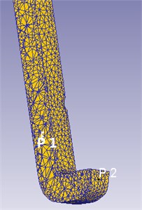
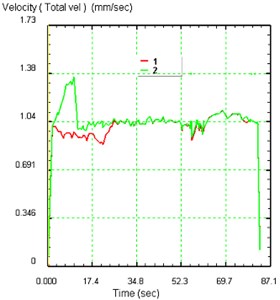
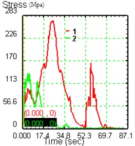
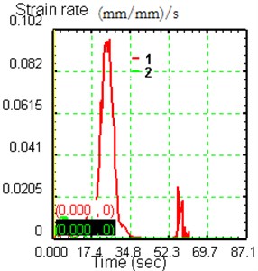
Fig. 5The change of effective stress and strain rate with time
3.3. Stress strain analysis
Fig. 5 shows the effective stress and strain rate change diagram of point 2, point two 5 tracking points. From the graph, the effective stress and the effective stress of the 1 position at the beginning point of the 2 position increases rapidly with the same trend, and the maximum value is 137 MPa and 100 MPa, and the effective stress at 1 points and 2 points are beginning to change. After 1 points above the die channel has been in the corner, also did not enter into the corner, so the effective stress in the 1 largely by 2 by the effective stress, so 1 has been smaller and the point 2 of the effective stress changes, and the same trend. At the beginning of the effective stress, the effective stress of point 2 is decreased and increased rapidly. It is because the material flow rate of 2 is higher than that of the inner flow velocity, which is affected by the surface friction. Since then, the effective stress of the point 2 is beginning to drop quickly, and the effective stress and effective strain rate of point 1 continues to rise, because the material has gradually entered into the corner, the effective stress reaches the maximum value 269 MPa, the effective strain rate reached 0.0967 (mm/mm)/s point 1 is in the corner. From Fig. 5 can be seen, the effective stress at the point of 1 at the time of the rapid increase to 152 MPa, the effective strain rate is also rapid increase to 0.0252 (mm/mm)/s at this point 1 in the material has been to the concave die, it is because the extrusion die part of the material is not used to undertake and hanging in the concave die, the point is located in the position of the force is the fulcrum, so the effective stress and the effect of the 1 has a rapid rise in the rapid rise of the process. The effective stress and effective strain rate in the extrusion process are the same as that of the change trend. In the actual operation, it is not only to reduce the stress concentration at the exit of the die, but also to improve the life of the die, and also to ensure the flatness of the billet.
Fig. 6Initial state grain size and distribution
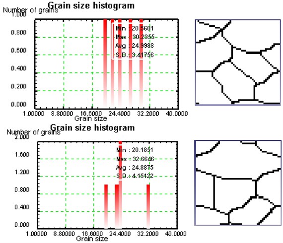
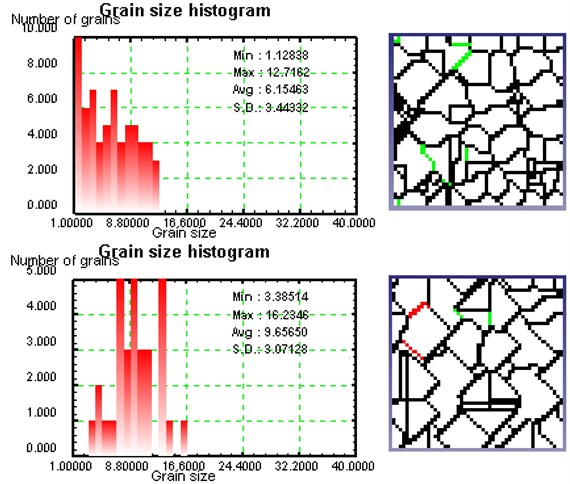
Fig. 7Single channel after extrusion of the grain size and distribution
3.4. Grain size analysis
In order to study the influence of the single pass ECAP method on the grain size of the billet, the grain size and distribution of the surface of the billet were randomly selected from points 1 and points 2.
Figure 6 is expressed as the initial state grain size and distribution of the initial state of the 2 points. From the graph, the average grain size of the billet at 2 tracking points is 28 μm, and the grain boundaries are obvious. Single channel after extrusion of the grain size and distribution as shown in Figure 7. The average grain size of 2 points is reduced, and the grain size of points 1 is the most obvious. The reasons are that the grain size of 2 points is not uniform, the metal flow velocity and the effective stress and strain of the billet are not uniform, which leads to the uneven distribution of grain size and the distribution of the different positions of the billet. From the previous analysis near the channel inner corners of the material resistance and friction, the stress concentration, maximum shear stress, resulting in a 1 point minimum grain size refinement, the most obvious effect.
4. Conclusions
1) The friction force has a great influence on the load of the extrusion process. The lubrication of the die can be strengthened during the process of the actual extrusion. The extrusion load and energy consumption can be reduced to a large extent.
2) The variation of the effective stress and strain rate is basically the same as that of the extrusion. In addition, the back extrusion of the material in the die exit will also be subject to stress concentration, the actual production of the material should be in the export of the billet to guide to ensure the flatness of the billet.
3) The grain size of the material is fine, but the grain size and the distribution of different positions are not uniform, but it is necessary to rotate the billet, so that the grain size is uniform.
References
-
Tan Shuqing, Wang Jingtao Metal Plastic Processing Physical Basis. Shaanxi Science and Technology Press, Shaanxi, 1996.
-
Sevillano J. Gil, Houtte P. Van, Aernoudt E. Large strain work hardening and textures. Progress in Materials Science, Vol. 25, Issues 2-4, 1980, p. 69-134.
-
British Wei Hou Material Forming and Control Engineering Graduate Design (Thesis) to Guide. Mechanical Industry Press, Beijing, 2015.
-
Nizheng Shun, Liu Shibo, He Chang Numerical simulation and polygon aluminum extrusion die design optimization. Thermal Processing, Vol. 11, 2012, p. 221-226.
-
Liu Shiguang, Zhang Tao Elastoplastic Mechanics Basic Theory. Huazhong University of Science and Technology Press, Wuhan, 2008.
-
Ren Guocheng ECAP of AZ31 Magnesium Alloy Extrusion Process of Plastic Deformation and Microstructure Evolution. Shandong University, Shandong, 2013.
