Abstract
Flexible manipulators have been actively used in various fields, such as aerospace, industry and medical treatment. It remains that the tip of the flexible manipulator should accurately trail the target trajectory without vibration. This paper proposes a novel method of the tip position control of a single flexible manipulator based on LQR with the Mamdani model. Firstly, using the assumed mode method and the Lagrange equations, the dynamic model of the single flexible manipulator is established. Then, the state equations are derived by the dynamic model. Based on the Mamdani model, the fuzzy algorithm is added to the traditional LQR control, and the self-adaptive adjustment of the LQR control variable R is conducted, which improves the adaptability of the control system. Finally, numerical simulations and experiments are presented. The results demonstrate that the novel control method presented in this paper can rapidly achieve the location in the position control and effectively suppress the elastic vibration of the single flexible manipulator, which has more considerable effect compared with the traditional LQR control method.
1. Introduction
In recent years, the robotic technology has been widely used in many areas, such as aerospace, industry and medical treatment. Due to the characteristics of high speed, high precision and high loading weight ratio, flexible structures have received great attention in the robot areas [1]. As a kind of representative flexible structure, the flexible manipulator has the advantages of less material used, lightweight and lower energy consumption, and has attracted numerous savants’ interests [1-9]. For the properties of low stiffness and small damp, the flexible manipulator is easy to produce elastic deformation to generate elastic vibration in the process of movement or localization. The elastic vibration of flexible manipulator is difficult to rapid attenuation and seriously affecting the operation accuracy, working efficiency and stability. Therefore, it is necessary to consider the flexible and dynamic characteristics in the research of tip position control and then design the controller to suppress the elastic vibration.
Several approaches utilizing closed-loop control strategies have been presented in the control of flexible manipulators [2]. These approaches include PID control [3], variable structure control [4], adaptive control [5], optimal control [6], robust control [7], intelligent control based on neural networks [8] and fuzzy logic control schemes [9]. Among them, the optimal control method is the most theoretically complete. In the optimal control theory, linear quadratic regulator (LQR) control algorithm is a popular method which is used to analyze a system by employing state-space method. The system can be stabilized using full-state feedback system by designing a LQR controller which is developed to determine the value of the gain of the state feedback control [10]. Thus, numerous LQR methods have been used in the vibration suppression or tip position control of flexible manipulators. A traditional LQR control method based on state space model of the flexible joint system was designed and verified by Yuan [11]. Baroudi [6] carried on the simulations and experiment for flexible manipulators using LQR method based on the tip deflection feedback. The experiment proved that the LQR control method is effective. Computed torque control and a composite control, based on the singular perturbation theory, were utilized to reduce mechanical vibrations of the flexible-link by El-Badawy [12]. In the composite control system, LQR control was designed for fast subsystem and enable better tip positioning. Ahmad [2] has designed an LQR with non-collocated PID controller and used the full-state feedback as an input to optimize the control gain matrix for rigid body motion control, while the tip position elastic deformation was used as input to a separate non-collocated control law for vibration control, which improved the overall performance.
A review of these literatures can be found that, in order to reduce the tracking error as soon as possible, the traditional LQR control method is easy to introduce larger control quantity in the early stage. For instance, the numerical simulations in literature [13] indicated that there was a larger control quantity in the process of the LQR control and a higher requirement for the control equipment. Moreover, the larger control quantity may increase the elastic vibration of flexible manipulators and impact the control effect of the system [6]. The most existing methods that artificial limit the maximum of control quantity have bad performance in adaptation and control effect of the system [14]. Thus, uniting other algorithm to improve the control performance is necessary. It is known that, based on the fuzzy sets, fuzzy language variables and fuzzy logic inference, as a popular nonlinear control theory, fuzzy control has been widely used in industrial control systems. Using fuzzy control method, the control quantity can be adjusted adaptively according to expertise and used to improve the control effect of the LQR control method studied in this paper. The inference algorithm of fuzzy controller is based on Mamdani model, which is good at expressing human empirical knowledge and processing fuzzy information according to each component of the independent and the parameters are easy to be set. Therefore, combing the fuzzy control and LQR control method, this paper proposes a novel tip position control method of single flexible manipulators.
The paper is organized as follows: ‘Dynamic model of the single flexible manipulator’ is stated in the following section. ‘Model of the control system’ section presents the model of the control system based on the dynamic model. Subsequently, a controller is designed for tracking and the control of tip position of single flexible manipulators in section ‘Design of the control system’ of this article. Then, simulated results for illustrating the effectiveness of the proposed control method are given in ‘Simulations and experiments’ section. The paper is concluded with a brief summary in last section.
2. Dynamic model of the single flexible manipulator
The structure diagram of the single flexible manipulator in the horizontal plane studied in this paper is shown in Fig. 1.
Fig. 1Structure diagram of the single flexible manipulator
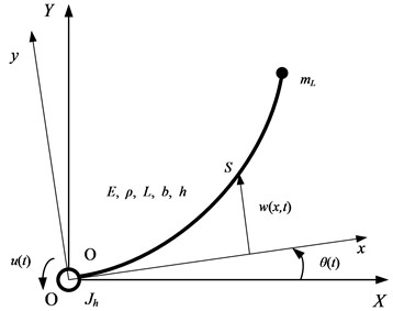
In Fig. 1, the coordinates XY and xy indicate the inertial frame and the reference frame, respectively. And u(t) is the control torque of the motor, Jh is the rotational inertia of the motor shaft and fixture, mL is the tip mass of the single flexible manipulator, θ(t) is the revolving angle of the motor, w(x,t) denotes the elastic deformation of point S on the single flexible manipulator with respect to the xy reference frame. E, ρ, L, b and h denote the elastic modulus, density, length, width of cross section and height of cross section of the single flexible manipulator, respectively.
In accordance with the assumed mode method, w(x,t) is written as [15]:
where Wi(x) is the ith mode shapes, qi(t) is the ith mode generalized coordinates.
According to the Euler-Bernoulli beam theory, the dynamic equations of the single flexible manipulator are established based on the Lagrange equations and expressed as follows:
where (∙) denotes the time derivative; J, Wi(L), σi, Mi and Ki are the constant coefficients given in the Appendixes.
3. Model of the control system
The state vector is selected as z=[θq1(t)…qN(t)]T, the dynamic Eq. (2), Eq. (3) can be written as following matrix equation:
where M, K and F are constant coefficient matrices given in the Appendixes.
Due to the existence of damping during movement of the single flexible manipulator, the damping of the joint and the structural damping of the single flexible manipulator are considered. The damping of the joint is considered for viscous damping, and the structural damping of the single flexible manipulator adopts proportional damping of the dynamic structure. The damping matrix is written as follows:
where CH is the viscous damping of the joint, α is the damping coefficient of mass. Substituting Eq. (5) into Eq. (4), Eq. (4) can be further written as:
Giving a linear time invariant state-space model of the system which is shown as [16]:
where, the state vector is defined as x(t)=[zT˙zT]T, and the coefficient matrices are obtained as follows:
Considering the real execution of the single flexible manipulator, we regard the tip angle of the single flexible manipulator as the control objective, which is denoted as θL. The revolving angle of the motor is denoted as θ(t) and L is the length of the single flexible manipulator. Due to the small tip deflection, the tip deflection angle of the single flexible manipulator approximately is equal to the tip deflection. The output of the system is expressed as:
Thus, the output matrix C is expressed as:
4. Design of the control system
With the obtained state space model of the system, the LQR controller is designed. The traditional LQR control method is easy to introduce larger control quantity in the early stage, which will increase the elastic vibration of flexible manipulators and impact the control effect of the system, the LQR control method and the fuzzy algorithm based on the Mamdani model are combined in this paper to improve the tip position control of single flexible manipulators.
According to the linear quadratic regulator theory, a reciprocal relationship is existed between Q and R. Therefore, the control variable Q is selected as a fixed value, while the control variable R is selected as a time-varying value, which is denoted as R(t). By choosing appropriate fuzzy self-adaptive algorithm, the control variable R(t) can be corrected, as well as the adaptability of the control system is improved to achieve better control effect.
4.1. Design of LQR controller
From the practical engineering application, the tip position control of the single flexible manipulator approaches to the target location under certain input. Namely, with the effect of the expected output signal, the actual output trajectory of the system can follow the change of the output signal.
The expected steady output vector is denoted as yr(t), while the actual output is denoted as y(t). The error e(t) is expressed as:
Thus, the performance indicator is expressed as:
where u(t) represents the input or control variable of the system.
If {A,B} is controllable for all states, as well as {A,C} is observable for all states, the approximate optimal control is expressed as [17]:
where P is obtained by the following Riccati equation [18]:
4.2. Design of LQR controller combining fuzzy algorithm
In the LQR controller, the control variable R is selected as a time-varying value which is denoted as R(t) and realized by fuzzy self-adaptive algorithm. Based on the two-dimensional fuzzy controller, the tip angle error e and error change ec are selected as the inputs of fuzzy controller and the control variable R(t) is selected as the output of fuzzy controller. Linguistic variables corresponding to seven different linguistic terms, {NB, NM, NS, ZO, PS, PM, PB}, abbreviation of ‘Negative Big’, ‘Negative Middle’, ‘Negative Small’, ‘Zero’, ‘Positive Small’, ‘Positive Middle’, ‘Positive Big’, respectively. In addition, one should define the relevant proportional factors from the experimental test data to linguistic levels. The linguistic variables E, EC and Rt represent error e, error change ec, and control variable R(t) in the fuzzy set [19]. The universes of discourses of the E, EC and Rt are from –1 to 1 rad, –1 to 1 rad/s and 0 to 1, respectively. Then [19]:
where, k1=1/|emax|, and emax is the maximum error value.
where, k2=1/|ecmax|, and ecmax is the maximum error change value.
where, k3=Rmax/1, and Rmax is the maximum value allowed for control variable.
The maximum value of error e, error change ec and control variable R(t) are chosen from numerical simulations.
Seven linguistic levels (NB, NM, NS, ZO, PS, PM, PB) are used to represent the input domain and output domain with their membership values lying between 0 and 1 [19]. The basic triangular and Z forms are chosen for the input and output membership functions [20, 21]. In order to suppress the control quantity which can be indicated as the control torque u(t), R(t) in the early stage of control should has a larger value than the other stages. However, in order to get a rapid response speed, the value of R(t) in the later stage of control should smaller. Therefore, when it comes to both ends of the function, the membership functions’ density of R(t) should be bigger than the middle part. In addition, according to the changes of the tip angle error e and error change ec in numerical simulation, we can get the membership functions of the error e and error change ec [22]. The membership functions are employed to convert these input and output variables into linguistic control variables (NB, NM, NS, ZO, PS, PM, PB) and the membership functions are shown in Fig. 2.
Table 1 shows the generated fuzzy inference rules of fuzzy controller [20], and the surface of the fuzzy rules is shown in Fig. 3. The rules are designed based on the changes of the tip angle error e and error change ec. In the early stage of control, the values of the error e and error change ec are larger than other stages and the control variable R(t) should be also lager than other stages to suppress the control torque u(t). However, in the later stage of control, the values of the error e and error change ec decrease and the control variable R(t) is reduced to get a rapid response speed. Moreover, the fuzzy inference rules have been adjusted based on the same simulations.
Fig. 2Membership functions of fuzzy controller: a) linguistic variable E; b) linguistic variable EC; c) linguistic variable Rt; d) schematic of fuzzy inference
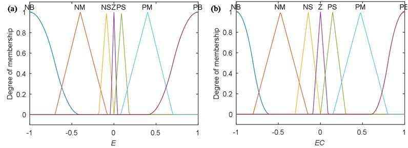
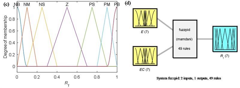
Table 1Fuzzy inference rules of fuzzy controller
Rt | E | ||||||
EC | NB | NM | NS | ZO | PS | PM | PB |
NB | PB | PM | PS | ZO | PS | PB | PB |
NM | PM | PS | ZO | NS | ZO | PM | PB |
NS | PS | ZO | NS | NM | NS | PM | PM |
ZO | ZO | NS | NM | NB | NM | PS | PM |
PS | PS | ZO | NS | NM | NS | PM | PM |
PM | PM | PS | ZO | NS | ZO | PM | PB |
PM | PB | PM | PS | ZO | PS | PB | PB |
Finally, the flowchart of the LQR controller combining fuzzy algorithm is illustrated in Fig. 4. The control variable R(t) of LQR controller is obtained by fuzzy controller and the self-adaptive adjustment of control system is done.
5. Simulations and experiments
To verify the control strategy on the tip position of the single flexible manipulator, numerical simulations and experiments are conducted in this section. The single flexible manipulator used is made of fiberglass colophony and the structural parameters are given in Table 2.
Fig. 3Surface of the fuzzy rules
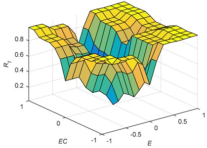
Fig. 4Flowchart of the LQR controller combining fuzzy algorithm
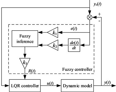
Table 2The structural parameters of the single flexible manipulator
Parameter | Value | Unit |
Rotational inertia Jh | 9.4×10⁻³ | kg·m2 |
Tip mass mL | 0.03 | kg |
Elastic modulus E | 25 | GPa |
Density ρ | 2.03×10³ | kg/m3 |
Length L | 0.4 | m |
Width of cross section b | 0.039 | m |
Height of cross section h | 0.00275 | m |
5.1. Simulations of the control system
Owing to the lower order modes play leading role in the vibration of the flexible manipulator, in order to simplify the computation, only the first order mode is considered in the simulations. The single flexible manipulator is assumed to rotate 1 rad by the driving of the motor, and rapidly achieve the location by the feedback control law for control torque between the motor and the flexible manipulator. The universe of discourse of the error e, error change ec and control variable R(t) are estimated by the simulations of the tip position control method of the single flexible manipulator based on the traditional LQR control method. Besides, the optimal control variables of the traditional LQR control method are also selected by the simulations. As mentioned, there is a reciprocal relationship between Q and R. So, the control variable Q is selected as a fixed value 30, and the values of R are 0.8, 1.5, 3 and 6. The simulation curves based on the traditional LQR control method are shown in Fig. 5.
Fig. 5Simulation curves of the single flexible manipulator: a) tip angle; b) control torque
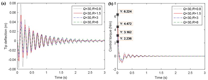
The tip angle of the single flexible manipulator are shown in Fig. 5(a), it indicates that when the value of R is 0.8 or 1.5, the convergence speeds are very close, and better than that when the value of R is 3 or 6. As shown in Fig. 5(b), the results of the control torque of the motor indicate that the maximum control torque is about 6.224 Nm when the value of R is 0.8 and the maximum control torque is about 4.472 Nm when the value of R is 1.5. For security reasons, each one of the motor of manipulator joints has a maximum allowed output torque. When the torque exceeds the maximum allowed torque, the output torque of the motor can’t meet the requirement of control system, and affects the control effect of the system [14]. Therefore, it is better that the value of R is 1.5 and the optimal control variables of the traditional LQR control method are selected: the Qand R are 30 and 1.5, respectively.
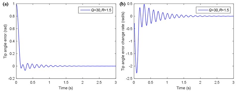
The tip angle error e and the tip angle error change ec based on the traditional LQR control method are shown in Fig. 6. From Fig. 6, it is obtained that the maximum of the absolute values of the error e and error change ec are 1 rad and –2.283 rad/s, respectively. Therefore, the scaling factors k1 and k2 is chosen by the simulation curves and recorded as k1= 1, k2= 0.4, while the scaling factor k3 is decided by experience and the value is k3=6. Besides, the changes of the error e and error change ec can also optimize the design of the membership functions and fuzzy inference rules.
Fig. 6Simulation curves of the single flexible manipulator based on the traditional LQR control method with the optimal control variables: a) tip angle error e; b) tip angle error change ec
Based on the analysis above, the simulations of the tip position control method of the single flexible manipulator based on LQR with the Mamdani model are carried out. What is more, the control effect of the new control method is compared with the traditional LQR control method to study the change of performance. The control variable R(t), tip angle, control toque, work of the motor, tip deflection and power spectral density (PSD) of the tip deflection based on LQR with the Mamdani model and the traditional LQR control methods are shown in Fig. 7.
Fig. 7(a) shows the relation curve of the control variable R(t) with time, which is adjusted by fuzzy controller.
Fig. 7(b) shows the tip angle of the single flexible manipulator. When the time is around 1.36 s, the single flexible manipulator is stabilized at the objective position by the method based on LQR with the Mandani model, and the maximum overshoot is 1.058 rad, while the traditional LQR control method takes about 1.96 s, and the maximum overshoot is 1.073 rad. When the fuzzy algorithm is added to the control of LQR, the control time is shortened by 30.6 %, the overshoot is reduced by 1.4 %. Meanwhile, it is evident from Fig. 7(c) that the response of the novel method is faster than the traditional LQR method in the position control.
Fig. 7(c) shows the tip deflection of the single flexible manipulator in a time-domain. It is obtained from the figure that the maximum tip deflection of the single flexible manipulator using the method based on LQR with the Mamdani model is about 0.035 m, while that of the traditional LQR control method is about 0.055 m. When the fuzzy algorithm is added to the control of LQR, the maximum of tip deflection is reduced by 36.4 %. Besides, the simulation curve based on LQR with the Mamdani model has faster convergence speed, which has better effect on suppression of the tip deflection.
Fig. 7Simulation curves of the single flexible manipulator: a) time-varying control variable Rt; b) tip angle; c) tip deflection; d) PSD of the tip deflection; e) control torque; f) work of the motor
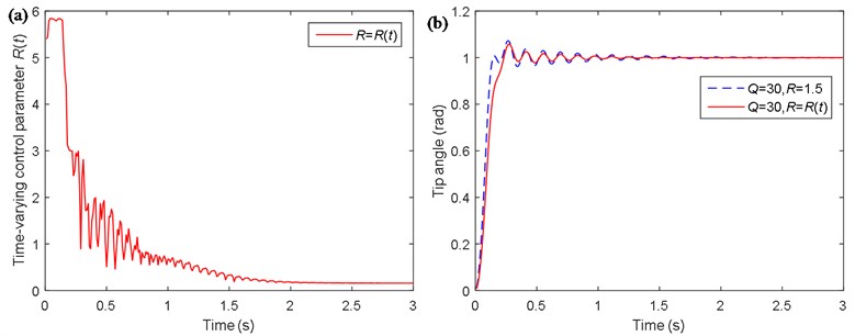
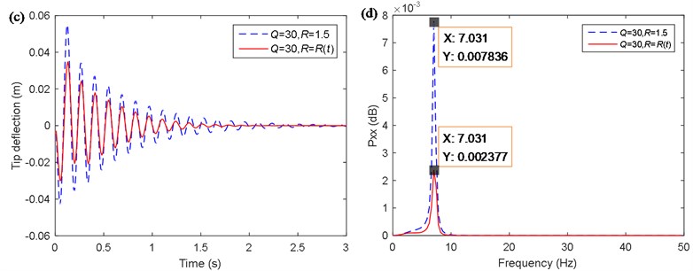
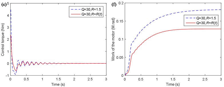
Fig. 7(d) shows the tip deflection of the single flexible manipulator in the frequency domain. It should be noted that, in order to verify the control method only the first mode is considered in the simulations. The PSD of the tip deflection only includes the first order natural frequency and the value is 7.03 Hz. Besides, in terms of the power spectral density of the tip deflection, the magnitude by the method based on LQR with the Mamdani model is about 0.0024 dB, while that of the traditional LQR control method is about 0.0078 dB. When the fuzzy algorithm is added to the control of LQR, the magnitude of the power spectral density of the tip deflection is reduced by 69.2 %.
Fig. 7(e) shows the control torque of the motor. It is obtained that the maximum control torque using the method based on LQR with the Mamdani model is about 2.35 Nm, while that of the traditional LQR control method is about 4.47 Nm. When the fuzzy algorithm is added to the control of LQR, the maximum of the control torque is reduced by 47.4 %.
Fig. 7(f) shows the work of the motor. From the aspect of the energy required, the work of the motor is about 0.13 M·rad using the method based on LQR with the Mamdani model, while the value is about 0.18 M·rad using the traditional LQR control method. When the fuzzy algorithm is added to the control of LQR, the work of the motor is reduced by 27.8 %.
5.2. Experiments of the control system
According to the above-mentioned theoretical analysis and simulated results, the experiments on active vibration control of the single flexible manipulator is conducted and the experimental apparatus of the overall experimental setup is depicted in Fig. 8. The properties of the experimental apparatus are consistent with that of the numerical simulation and the flowchart of active vibration control experiments is shown in Fig. 9.
Fig. 8Photograph of the experimental apparatus
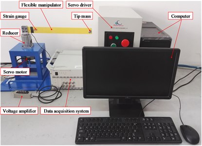
Fig. 9Flowchart of the experiments

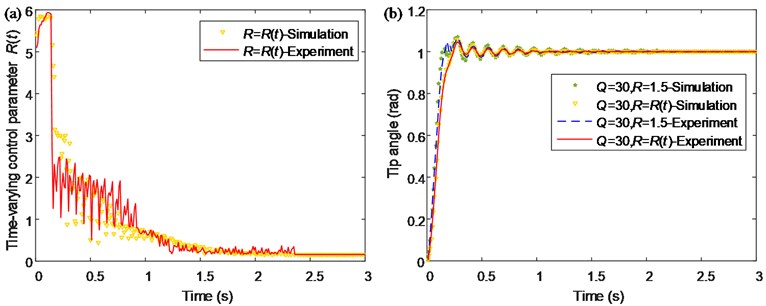
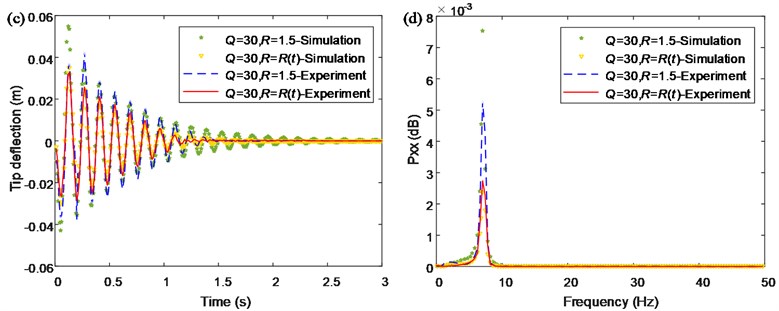
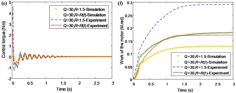
The comparison between the simulated and experimental results of the single flexible manipulator are shown in Fig. 10. It can be seen that the results of the experimental results are good agreement with the simulation result in Fig. 7. Besides, the results demonstrate that the effect of the proposed control method is considerable compared with the traditional LQR control method. In addition, it should be noted that the results exhibit a certain error between the simulated and experimental results, and this is mainly caused by the difference between experiment system and dynamic model, such as viscous damping, air resistance, the machining precision of structure, the precision of sensors and so on.
The results of the numerical simulations above indicate that the method based on LQR with the Mamdani model is self-adaptive for the tip position control of the single flexible manipulator and has more excellent performance than traditional LQR control method. Moreover, compared with the traditional LQR control method, the value of R(t) is larger in the early stage using this novel control method, which effectively suppresses the amplitude of the control torque u(t) and thereby reduces the maximum tip deflection of the single flexible manipulator. In the mid and latter stages of control, the value of R(t) is gradually reduced. Therefore, it leads to a gradual relative increase of the proportion of the control variable Q and improve the response characteristic of the system in the mid and latter stages of control. In addition, the experiments on active vibration control of the single flexible manipulator achieves the desired results of the numerical simulations. The simulated and experimental results have good consistency and demonstrate that the proposed control method can control the tip position of the single flexible manipulator correctly, and the improved control method has more excellent performance.
Fig. 10Comparison between the simulated and experimental results of the single flexible manipulator: a) time-varying control variable Rt; b) tip angle; c) tip deflection; d) PSD of the tip deflection; e) control torque; f) work of the motor
6. Conclusions
This paper focuses on the tip position control of single flexible manipulators. Based on the assumed mode method and the Lagrange equations, the dynamic model of the single flexible manipulator with a tip mass is established and the state equations of the system are derived. Considering the traditional LQR control method is easy to introduce larger controlled quantity in the early stage, a novel method of the tip position control of single flexible manipulators is established based on the fuzzy algorithm based on the Mamdani model. By choosing appropriate fuzzy rules, the control variables of LQR can be corrected, as well as the adaptability of the control system is improved to achieve better control effect. And according to the change of the fuzzy inferential input, the membership functions are optimized to achieve better control effect.
The results of numerical simulations showed that the novel method improved the response speed of the system, as well as the maximum of the tip deflection and the control torque of the single flexible manipulator is reduced. Moreover, with this novel control method, the work of the motor was reduced and more energy was saved in the process of control. Compared with the traditional LQR control method, the novel control method has a better performance and can rapidly achieve the location in the position control and effectively suppress the elastic vibration of the single flexible manipulator. Finally, the experiments on active vibration control indicates that the control effect reaches the expectation and the experiment results are consistent with simulation results, which further demonstrated the feasibility of the proposed control method.
References
-
Liu Yufei, Li Wei, Yang Xuefeng, et al. Coupled dynamic model and vibration responses characteristic of a motor-driven flexible manipulator system. Mechanical Sciences, Vol. 6, Issue 2, 2015, p. 235-244.
-
Ahmad M. A. Vibration and input tracking control of flexible manipulator using LQR with non-collocated PID controller. 2008 Second UKSIM European Symposium on Computer Modeling and Simulation (EMS), Liverpool, UK, 2008.
-
Mohamed Z, Ahmad M. A. Hybrid input shaping and feedback control schemes of a flexible robot manipulator. IFAC Proceedings, Seoul, Korea, 2008.
-
Ingole A. R., Bandyopadhyay B., Gorez R. Variable structure control application for flexible manipulators. Proceedings of the IEEE Conference on Control Applications, New York, USA, 1994.
-
Jung H. Y., Feng L. L., Li C. F. Nonlinear adaptive control for flexible-link manipulators. IEEE Transactions on Robotics and Automation, Vol. 13, Issue 1, 1997, p. 140-148.
-
Baroudi M., Saad M., Ghie W. State-feedback and linear quadratic regulator applied to a single-link flexible manipulator. IEEE International Conference on Robotics and Biomimetics, Guilin, China, 2009.
-
Song G., Cai L. New approach to robust position/force control of flexible-joint robot manipulators. Journal of Robotic Systems, Vol. 13, Issue 7, 1996, p. 429-444.
-
Gutierrez L. B., Lewis P. L., Lowe J. A. Implementation of a neural network tracking controller for a single flexible link: comparison with PD and PID controllers. IEEE Transactions on Industrial Electronics, Vol. 45, Issue 3, 1998, p. 307-318.
-
Moudgal V. G., Passino K. M., Yurkovich S. Rule-based control for a flexible-link robot. IEEE Transactions on Control Systems Technology, Vol. 2, Issue 4, 1994, p. 392-405.
-
Tao C. W., Taur J. S., Chen Y. C. Design of a parallel distributed fuzzy LQR controller for the twin rotor multi-input multi-output system. Fuzzy Sets and Systems, Vol. 161, Issue 15, 2010, p. 2081-2103.
-
Yuan H., Qiao Y. L., Li B. L., et al. Implementation of LQR control strategy in flexible joint system. Experimental Technology and Management, Vol. 23, Issue 8, 2006, p. 33-35.
-
El-Badawy A. A., Mehrez M. W., Ali A. R. Nonlinear modeling and control of flexible-link manipulators subjected to parametric excitation. Nonlinear Dynamics, Vol. 62, Issue 4, 2010, p. 769-779.
-
Wei Y. D., Lou J. Q., Lv Y. G., et al. Research on linear quadratic optimal control problem in active vibration control. Journal of Zhejiang University (Engineering Science), Vol. 43, Issue 3, 2009, p. 420-424.
-
Su Y. X. Control Theory of Nonlinear Robot System. Sciences Press, Beijing, 2008.
-
Liu Yufei, Li Wei, Yang Xuefeng, et al. Vibration response and power flow characteristics of a flexible manipulator with a moving base. Shock and Vibration, 2015, p. 1-8.
-
Vinodh K. E., Jovitha J. Robust LQR controller design for stabilizing and trajectory racking of inverted pendulum. International Conference on Design and Manufacturing, Coimbatore, India, 2013.
-
Hu S. S., Wang Z. Q., Hu W. L. Optimal Control Theory and System. Second Edition, Sciences Press, Beijing, 2005.
-
Chingiz H., Sıtkı Y. V. L. LQR controller with Kalman estimator applied to UAV longitudinal dynamics. Scientific Research Publishing, Vol. 4, 2013, p. 36-41.
-
Wei J. J., Qiu Z. C., Han J. D., et al. Experimental comparison research on active vibration control for flexible piezoelectric manipulator using fuzzy controller. Journal of Intelligent and Robotic Systems, Vol. 59, Issue 1, 2010, p. 31-56.
-
Ahmad M. A., Tumari M. Z. M., Nasir A. N. K. Composite Fuzzy Logic control approach to a flexible joint manipulator. International Journal of Advanced Robotic Systems, Vol. 10, Issue 58, 2013, p. 1-9.
-
Liu J. K. Advanced PID control and MATLAB simulation. Second Edition, Publishing House of Electronics Industry, Beijing, 2004.
-
Khoury G. M., Saad M., Kanaan H. Y., et al. Fuzzy PID control of a five DOF robot arm. Journal of Intelligent and Robotic Systems: Theory and Applications, Vol. 40, Issue 3, 2004, p. 299-320.
Cited by
About this article
This research work was partially supported by the National Natural Science Foundation of China (No. 51305444 and No. 51307172), the Doctoral Fund of Ministry of Education under Grant (No. 20120095120013), the Scientific and Technological Projects of Jiangsu Province (BY2014028-06) and A Project Funded by the Priority Academic Program Development of Jiangsu Higher Education Institutions (PAPD).
En Lu contributed to the conception of the study and wrote the manuscript. Xuefeng Yang contributed significantly to analysis and manuscript preparation. Wei Li played an important role in interpreting the results. Yuqiao Wang performed the data analyses. Mengbao Fan helped perform the analysis with constructive discussions. Yufei Liu revised the manuscript.

